Large-Scale Space-Based Solar Power Station: Multi-Scale Modular Space Power
Atwater; Harry A. ; et al.
U.S. patent application number 14/712783 was filed with the patent office on 2016-12-29 for large-scale space-based solar power station: multi-scale modular space power. This patent application is currently assigned to California Institute of Technology. The applicant listed for this patent is California Institute of Technology. Invention is credited to Behrooz Abiri, Manan Arya, Harry A. Atwater, Florian Bohn, Jeffrey P. Bosco, Dennis Callahan, Melanie Delapierre, Seyed Ali Hajimiri, Nicolas Lee, Sergio Pellegrino, Emily C. Warmann.
| Application Number | 20160380580 14/712783 |
| Document ID | / |
| Family ID | 54480713 |
| Filed Date | 2016-12-29 |


View All Diagrams
| United States Patent Application | 20160380580 |
| Kind Code | A1 |
| Atwater; Harry A. ; et al. | December 29, 2016 |
Large-Scale Space-Based Solar Power Station: Multi-Scale Modular Space Power
Abstract
A space-based solar power station, a power generating satellite module and/or a method for collecting solar radiation and transmitting power generated using electrical current produced therefrom is provided. Each solar power station includes a plurality of satellite modules. The plurality of satellite modules each include a plurality of modular power generation tiles including a photovoltaic solar radiation collector, a power transmitter and associated control electronics. The power transmitters can be coordinated as a phased array and the power generated by the phased array is transmitted to one or more power receivers to achieve remote wireless power generation and delivery. Each satellite module may be formed of a compactable structure capable of reducing the payload area required to deliver the satellite module to an orbital formation within the space-based solar power station.
| Inventors: | Atwater; Harry A.; (South Pasadena, CA) ; Hajimiri; Seyed Ali; (La Canada, CA) ; Pellegrino; Sergio; (Pasadena, CA) ; Abiri; Behrooz; (Pasadena, CA) ; Bohn; Florian; (Pasadena, CA) ; Bosco; Jeffrey P.; (Los Angeles, CA) ; Callahan; Dennis; (Los Angeles, CA) ; Warmann; Emily C.; (Riverside, CA) ; Arya; Manan; (Pasadena, CA) ; Lee; Nicolas; (Pasadena, CA) ; Delapierre; Melanie; (Pasadena, CA) | ||||||||||
| Applicant: |
|
||||||||||
|---|---|---|---|---|---|---|---|---|---|---|---|
| Assignee: | California Institute of
Technology |
||||||||||
| Family ID: | 54480713 | ||||||||||
| Appl. No.: | 14/712783 | ||||||||||
| Filed: | May 14, 2015 |
Related U.S. Patent Documents
| Application Number | Filing Date | Patent Number | ||
|---|---|---|---|---|
| 61993016 | May 14, 2014 | |||
| 61993025 | May 14, 2014 | |||
| 61993957 | May 15, 2014 | |||
| 61993037 | May 14, 2014 | |||
| 62006604 | Jun 2, 2014 | |||
| 62120650 | Feb 25, 2015 | |||
| Current U.S. Class: | 244/158.4 |
| Current CPC Class: | H02J 3/383 20130101; H02S 40/42 20141201; H02J 50/90 20160201; H02S 20/25 20141201; H02J 50/80 20160201; B64G 1/222 20130101; H02J 2300/24 20200101; H02S 10/40 20141201; Y02B 10/10 20130101; B64G 1/405 20130101; B64G 1/407 20130101; H02S 30/10 20141201; H02S 40/36 20141201; B64G 1/288 20130101; H02J 50/23 20160201; H01L 31/042 20130101; B64G 1/36 20130101; B64G 1/283 20130101; B64G 1/401 20130101; B64G 1/66 20130101; H02S 40/30 20141201; B64G 1/428 20130101; H02S 30/20 20141201; B64G 2700/66 20130101; B64G 1/286 20130101; Y02E 10/52 20130101; H02S 20/30 20141201; H02J 3/381 20130101; B64G 1/406 20130101; B64G 1/44 20130101; B64G 1/403 20130101; B64G 1/1085 20130101; H02S 40/38 20141201; Y02E 10/56 20130101; B64G 1/443 20130101; H02J 50/30 20160201 |
| International Class: | H02S 20/32 20060101 H02S020/32; B64G 1/10 20060101 B64G001/10; H02J 50/40 20060101 H02J050/40; H02J 3/38 20060101 H02J003/38; H02J 50/80 20060101 H02J050/80; H02S 40/36 20060101 H02S040/36; H02J 50/90 20060101 H02J050/90; H02S 40/42 20060101 H02S040/42; B64G 1/24 20060101 B64G001/24; H02J 50/23 20060101 H02J050/23 |
Claims
1. A space-based solar power station comprising: a plurality of unconnected satellite modules disposed in space in an orbital array formation; a plurality of power generation tiles disposed on each of the plurality of satellite modules; at least one photovoltaic cell disposed on each of the power generation tiles; at least one power transmitter collocated with the at least one photovoltaic cell on each of the power generation tiles and in signal communication therewith such that an electrical current generated by the collection of solar radiation by the at least one photovoltaic cell powers the at least one power transmitter, where each of the at least one power transmitters comprises: an antenna; and control electronics that controls the phase of a radio frequency power signal that feeds the antenna so that the power transmitter is coordinated with power transmitters on other power generation tiles to form a phased array.
2. The space-based solar power station of claim 1, wherein satellite modules are disposed in a geosynchronous orbit.
3. The space-based solar power station of claim 1, wherein each of the satellite modules further comprises a propulsion system incorporating guidance control circuitry that controls at least one of an orientation and a position of each of the satellite modules within the orbital array formation.
4. The space-based solar power station of claim 1, wherein each of the power generation tiles further comprises one or more position sensors for determining a position of the antenna relative to the other antennas of the phased array.
5. The space-based solar power station of claim 1, wherein the control electronics receive location information from a reference signal to determine a location of the antenna.
6. The space-based solar power station of claim 5, wherein the reference signal is externally generated from one of either a global position system or an international ground station.
7. The space-based solar power station of claim 5, wherein the reference signal is generated locally on each of the satellite modules.
8. The space-based solar power station of claim 5, wherein the control electronics utilize the location information from the reference signal to coordinate the phase shift of the radio frequency power signal.
9. The space-based solar power station of claim 1, wherein the control electronics control the phase of the radio frequency power signal such that the directionality of the radio-frequency power signal is electronically steerable.
10. The space-based solar power station of claim 9, wherein the phase of the radio frequency power signals of each of the power transmitters is coordinated such that the radio frequency power signals are electronically steerable to one or more power receiving rectennas located remotely from the space-based solar power station.
11. The space-based solar power station of claim 1, wherein the control circuitry further comprises a power amplifier for converting the electrical current to the radio-frequency power signal.
12. The space-based solar power station of claim 1, wherein each of the satellite modules are in wireless communication with each of the other satellite modules such that at least phase control information is exchanged therebetween.
13. The space-based solar power station of claim 1, wherein the photovoltaic cell further comprises an absorber having a radiation shield disposed on a face thereof onto which the solar radiation is incident, and a conductive material disposed on an opposite face thereof.
14. The space-based solar power station of claim 13, wherein the absorber is formed from a material selected from the group of silicon, CdTe, and GaInP/GaAs.
15. The space-based solar power station of claim 1, wherein the power generation tiles further comprise a collector disposed thereon and configured to concentrate incident solar radiation on the photovoltaic cell.
16. The space-based solar power station of claim 15, wherein the collector is selected from the group consisting of Cassegrain, parabolic, nonparabolic, hyperbolic and combinations thereof.
17. The space-based solar power station of claim 1, wherein the power generation tiles further comprise a temperature management device configured to control the operating temperature of the power generation tile.
18. The space-based solar power station of claim 17, wherein the temperature management device comprises a radiative heat sink.
19. The space-based solar power station of claim 1, wherein the antenna is selected from the group consisting of dipole, helical and patch.
20. The space-based solar power station of claim 1, wherein the satellite modules are formed of at least two movably interrelated elements such that the dimensional extent of the satellite modules in at least one axis is compactible.
21. The space-based solar power station of claim 20, wherein the movably interrelated elements are foldable relative to each other by one of the following z-folding, fan-folding, double z-folding, Miura-ori, and slip-folding.
22. The space-based power station of claim 21, wherein the folded movably interrelated elements are further compacted by symmetric wrapping.
23. The space-based power station of claim 20 wherein the movably interrelated elements are prestressed such that a tensional force is distributed there across.
24. The space-based power station of claim 20, further comprising a deployment mechanism engageable with the at least two movably interrelated elements to apply a force thereto such that the elements are moved relative to each other on application of the force.
25. The space-based power station of claim 24, wherein the deployment mechanism comprises one or more elongated booms.
26. The space-based power station of claim 24, wherein the deployment mechanism comprises weighted elements, and wherein the force is applied by rotating the satellite module.
27. The space-based solar power station of claim 1, wherein each of the satellite modules are formed of a plurality of movably interrelated elements, and wherein the movably interrelated elements are slip-wrapped to reduce the dimensional extent of the satellite module along at least two axes.
28. The space-based solar power station of claim 27, wherein each of the plurality of movably interrelated elements are interconnected with each adjacent of the plurality of movable interrelated elements by a slip-fold, and wherein the edges of the plurality of movably interrelated elements are continuously interconnected.
29. The space-based solar power station of claim 1, wherein each of the plurality of power generation tiles are formed of a plurality of movably interrelated elements such that at least the photovoltaic cell and power transmitter of each power generation tile are movable relative to each other such that the dimensional extent of the power generation tiles are reducible along at least one axis.
30. The space-based solar power station of claim 29, wherein the movably interrelated elements of the power generation tiles are interconnected through one or more resilient members.
Description
RELATED APPLICATION
[0001] This application claims priority to U.S. provisional patent application Ser. No. 61/993,016 entitled "Large-Scale Space-Based Array: Packaging, Deployment and Stabilization of Lightweight Structures," filed on May 14, 2014; U.S. provisional patent application Ser. No. 61/993,025 entitled "Large-Scale Space-Based Array: Multi-Scale Modular Space Power System," filed on May 14, 2014; U.S. provisional patent application Ser. No. 61/993,957 entitled "Large-Scale Space-Based Array: Modular Phased Array Power Transmission," filed May 15, 2014; U.S. provisional patent application Ser. No. 61/993,037 entitled "Large-Scale Space-Based Array: Space-Based Dynamic Power Distribution System," filed May 14, 2014; U.S. provisional patent application Ser. No. 62/006,604 entitled "Large-Scale Space-Based Array: Efficient Photovoltaic Structures for Space," filed Jun. 2, 2014; and U.S. provisional patent application Ser. No. 62/120,650 entitled "Large-Scale Space-Based Array: Packaging, Deployment and Stabilization of Lightweight Structures," filed Feb. 25, 2015, all of which are incorporated by reference herein in their entirety.
FIELD OF THE INVENTION
[0002] The present invention is related to a space-based solar power station including a plurality of solar power satellite modules, more specifically to a modular space-based power station with a plurality of compactable independent solar power satellite modules flown in an orbital formation that by themselves or in unison form a phased and/or amplitude array at radio frequencies for power transmission from space to Earth, each module having a plurality of power generation tiles having integrated photovoltaic cells, antennas, thermal radiator and control circuits in varying configurations.
BACKGROUND
[0003] Space-based solar power (SBSP) describes the collection of solar power in space by a solar-power satellite or a satellite power system (SPS) and then the conversion and transmission of the power to a remote receiver for conversion back to electrical power. In an SBSP system, solar energy is collected as electrical energy on board, powering some manner of wireless power transmission to a receiver located remotely from the SBSP. The wireless power transmission application might include a microwave transmitter or laser emitter, which would direct its beam toward a collector, such as a power receiving rectenna at the remote location, such as, on the Earth's surface.
[0004] SBSP differs from ground-based solar collection methods in that the means used to collect energy resides on an orbiting satellite instead of on the Earth's surface. Basing such a system in space results in a higher collection rate for the solar energy due to the lack of a diffusing atmosphere. In a conventional ground-based system a large percentage (55-60%) of the solar energy is lost on its way through the atmosphere by the effects of reflection and absorption. Space-based solar power systems convert solar energy to a far-field emission such as microwaves outside the atmosphere, avoiding these losses. In addition, SBSP systems have a longer collection period and the ability to collect solar energy continuously without the downtime (and cosine losses, for fixed flat-plate collectors) that result from the Earth's rotation away from the sun.
[0005] A general limitation for SBSP systems is the size of SPS required to generate sufficient electrical power from solar energy. For example, for a 500 MW system a 5 km.sup.2 platform may be required. Such a platform would be formed of large satellites on the order to tens to hundreds of tonnes/satellite. The launch costs associated with placing such large structures into orbit reduces the economic viability of such SBSP systems.
SUMMARY
[0006] Systems and methods in accordance with various embodiments of the invention provide a space-based solar power (SBSP) system including a plurality of solar-power satellite modules. In a number of embodiments, the satellite modules include a plurality of modular power generation tiles combining at least one photovoltaic cell, a power transmitter and circuitry configured to perform a variety of control functions including (but not limited to) coordinating the participation of the power transmitter in a phased array. Embodiments also provide compactible structures, and methods and mechanisms for deploying such compactible light weight structures once in a selected operating location. A plurality of the standalone satellite modules may be collocated, and flown in any suitable orbital formation in space to collectively constitute the space-based solar power system.
[0007] Many embodiments are directed to a space-based solar power station including, a plurality of unconnected satellite modules disposed in space in an orbital array formation, a plurality of power generation tiles disposed on each of the plurality of satellite modules, at least one photovoltaic cell disposed on each of the power generation tiles, at least one power transmitter collocated with the at least one photovoltaic cell on each of the power generation tiles and in signal communication therewith such that an electrical current generated by the collection of solar radiation by the at least one photovoltaic cell powers the at least one power transmitter, where each of the at least one power transmitters includes: an antenna, and control electronics that controls the phase of a radio frequency power signal that feeds the antenna so that the power transmitter is coordinated with power transmitters on other power generation tiles to form a phased array.
[0008] In other embodiments the satellite modules are disposed in a geosynchronous orbit.
[0009] In still other embodiments each of the satellite modules further include a propulsion system incorporating guidance control circuitry that controls the orientation and position of each of the satellite modules within the orbital array formation.
[0010] In yet other embodiments each of the power generation tiles further includes one or more position sensors for determining the position of the antenna relative to the other antennas of the phased array.
[0011] In still yet other embodiments the control electronics receive location information from a reference signal to determine the location of the antenna. In some such embodiments the reference signal is externally generated from one of either a global position system or an international ground station. In other such embodiments the reference signal is generated locally on each of the satellite modules. In still other such embodiments the control electronics utilize the location information from the reference signal to coordinate the phase shift of the radio frequency power signal.
[0012] In still yet other embodiments the control electronics control the phase of the radio frequency power signal such that the directionality of the radio-frequency power signal is electronically steerable. In some such embodiments the phase of the radio frequency power signals of each of the power transmitters is coordinated such that the radio frequency power signals are electronically steerable to one or more power receiving rectennas located remotely from the space-based solar power station.
[0013] In still yet other embodiments the control circuitry further comprises a power amplifier for converting the electrical current to the radio-frequency power signal.
[0014] In still yet other embodiments each of the satellite modules are in wireless communication with each of the other satellite modules such that at least phase control information is exchanged therebetween.
[0015] In still yet other embodiments the photovoltaic cell further comprises an absorber having a radiation shield disposed on a face thereof onto which the solar radiation is incident, and a conductive material disposed on an opposite face thereof. In some such embodiments the absorber is formed from a material selected from the group of silicon, CdTe, and GaInP/GaAs.
[0016] In still yet other embodiments the power generation tiles further comprise a collector disposed thereon and configured to concentrate incident solar radiation on the photovoltaic cell. In some such embodiments the collector is selected from the group consisting of Cassegrain, parabolic, nonparabolic, hyperbolic and combinations thereof.
[0017] In still yet other embodiments the power generation tiles further comprise a temperature management device configured to control the operating temperature of the power generation tile. In some such embodiments the temperature management device comprises a radiative heat sink.
[0018] In still yet other embodiments the antenna is selected from the group consisting of dipole, helical and patch.
[0019] In still yet other embodiments the satellite modules are formed of at least two movably interrelated elements such that the dimensional extent of the satellite modules in at least one axis is compactible. In some such embodiments the movably interrelated elements are foldable relative to each other by one of the following z-folding, fan-folding, double z-folding, Miura-ori, and slip-folding. On other such embodiments the folded movably interrelated elements are further compacted by symmetric wrapping. In still other such embodiments the movably interrelated elements are prestressed such that a tensional force is distributed there across. In yet other such embodiments a deployment mechanism is engageable with the at least two movably interrelated elements to apply a force thereto such that the elements are moved relative to each other on application of the force. In still yet other such embodiments the deployment mechanism comprises one or more elongated booms. In still yet other such embodiments the deployment mechanism comprises weighted elements, and wherein the force is applied by rotating the satellite module.
[0020] In still yet other embodiments each of the satellite modules are formed of a plurality of movably interrelated elements, and wherein the movably interrelated elements are slip-wrapped to reduce the dimensional extent of the satellite module along at least two axes. In some such embodiments each of the plurality of movably interrelated elements is interconnected with each adjacent of the plurality of movable interrelated elements by a slip-fold, and wherein the edges of the plurality of movably interrelated elements are continuously interconnected.
[0021] In still yet other embodiments each of the plurality of power generation tiles are formed of a plurality of movably interrelated elements such that at least the photovoltaic cell and power transmitter of each power generation tile are movable relative to each other such that the dimensional extent of the power generation tiles are reducible along at least one axis. In some such embodiments the movably interrelated elements of the power generation tiles are interconnected through one or more resilient members.
[0022] The features and advantages described in the specification are not all inclusive and, in particular, many additional features and advantages will be apparent to one of ordinary skill in the art in view of the drawings, specification, and claims. Moreover, it should be noted that the language used in the specification has been principally selected for readability and instructional purposes, and may not have been selected to delineate or circumscribe the inventive subject matter.
BRIEF DESCRIPTION OF DRAWINGS
[0023] The description will be more fully understood with reference to the following figures and data graphs, which are presented as various embodiments of the disclosure and should not be construed as a complete recitation of the scope of the disclosure, wherein:
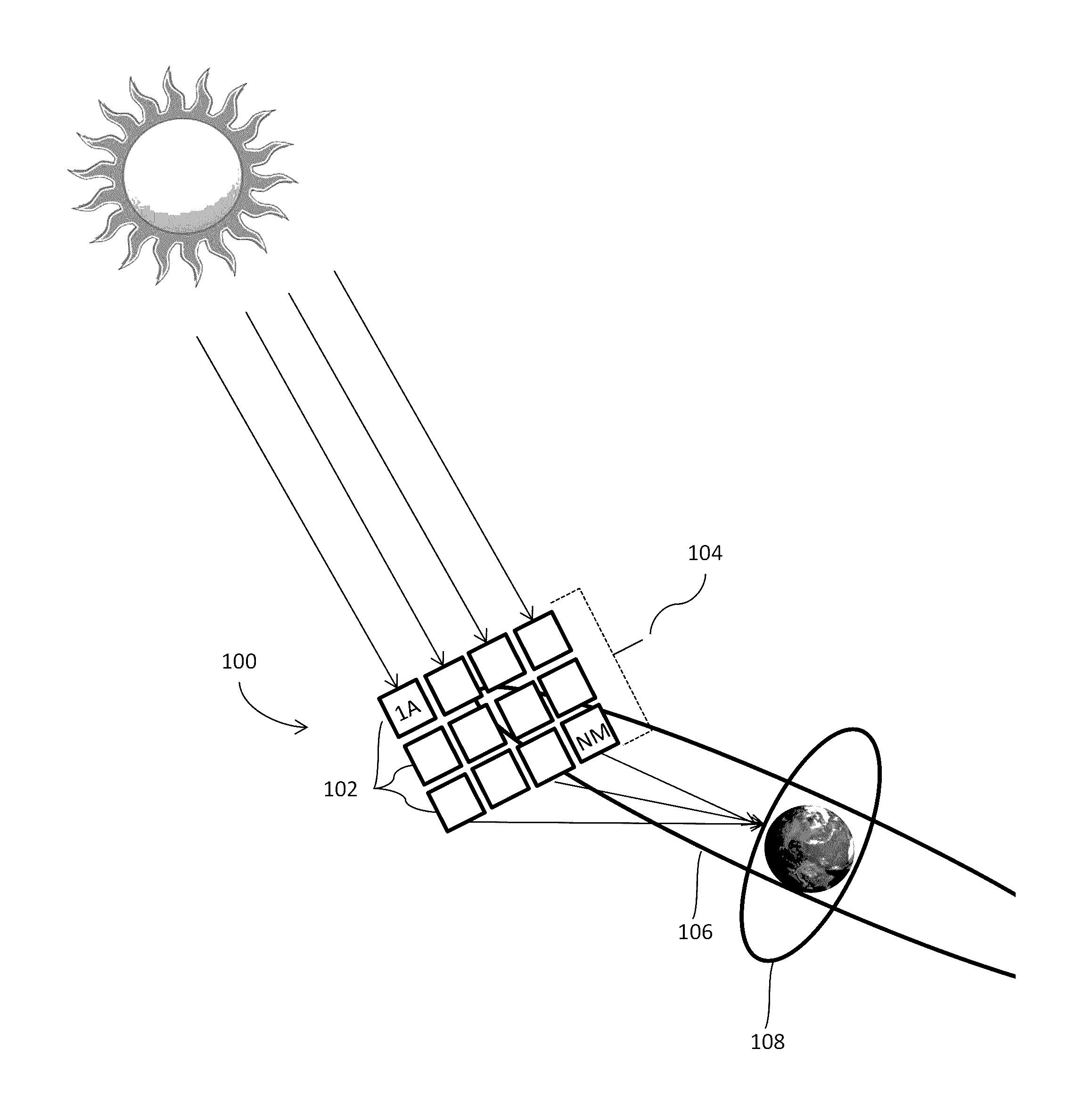
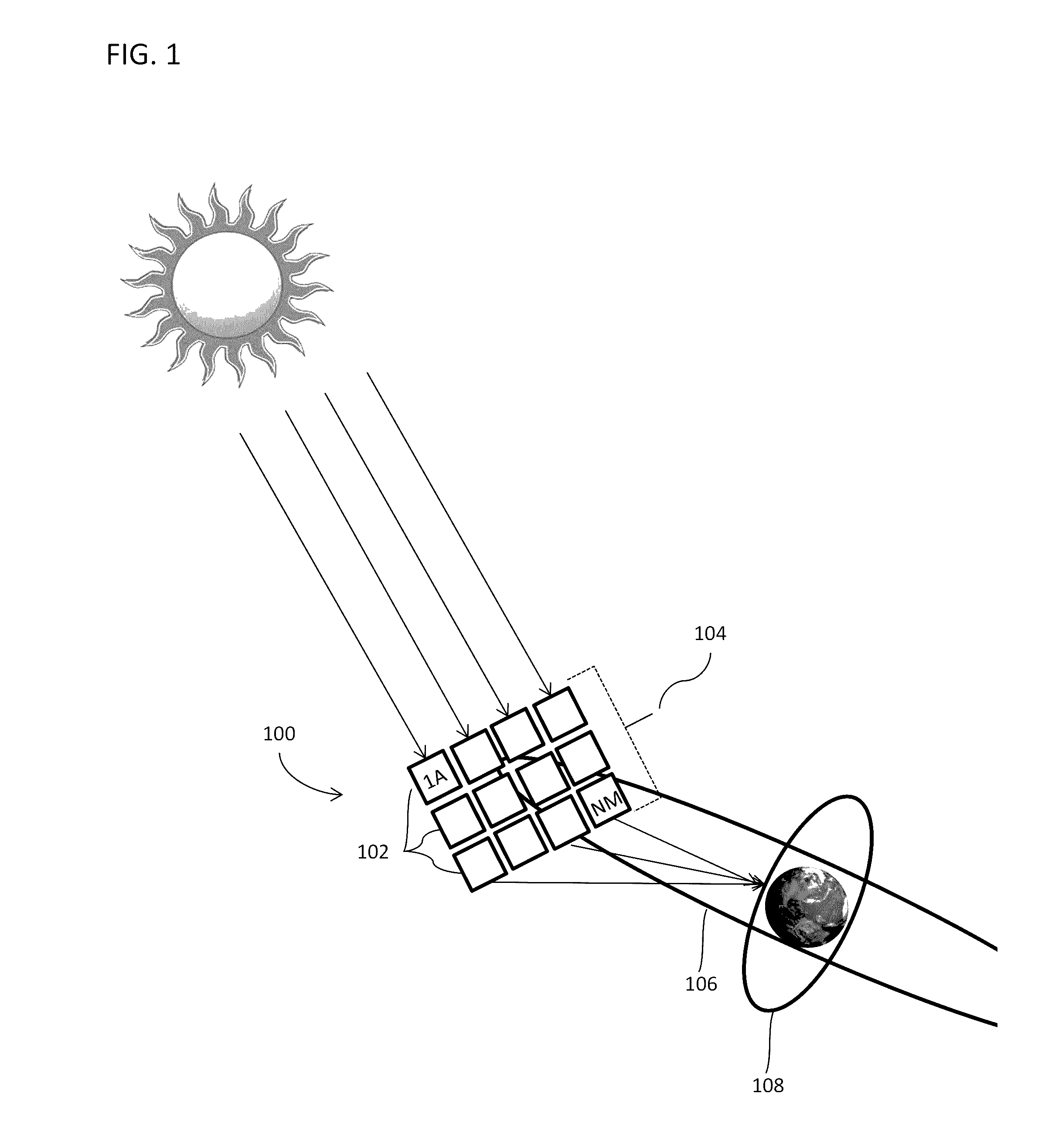
[0024] FIG. 1 conceptually illustrates a large-scale space-based solar power station with a plurality of power satellite modules in geosynchronous orbit about the Earth, according to one embodiment.
[0025] FIG. 2 conceptually illustrates a large-scale space-based solar power station with a plurality of power satellite modules flying in a rectangular orbital formation, according to one embodiment.
[0026] FIG. 3 conceptually illustrates a large-scale space-based solar power station, a satellite module, and a cross-sectional view of a modular power generation tile, according to one embodiment.
[0027] FIG. 4a conceptually illustrates a cross-sectional view of a modular power generation tile, according to one embodiment.
[0028] FIG. 4b conceptually illustrates a cross-sectional view of a photovoltaic cell, according to one embodiment.
[0029] FIG. 4c conceptually illustrates a block-diagram for an integrated circuit suitable for utilization in a power transmitter forming part of a power generation tile, according to one embodiment.
[0030] FIG. 5 conceptually illustrates an array of power generation tiles in which the antenna elements of the power generation tiles are configured as a phased array, according to one embodiment.
[0031] FIG. 6 conceptually illustrates the power density distribution at a ground receiver from a transmission of power from a phased array of antennas on a solar power station, according to embodiments.
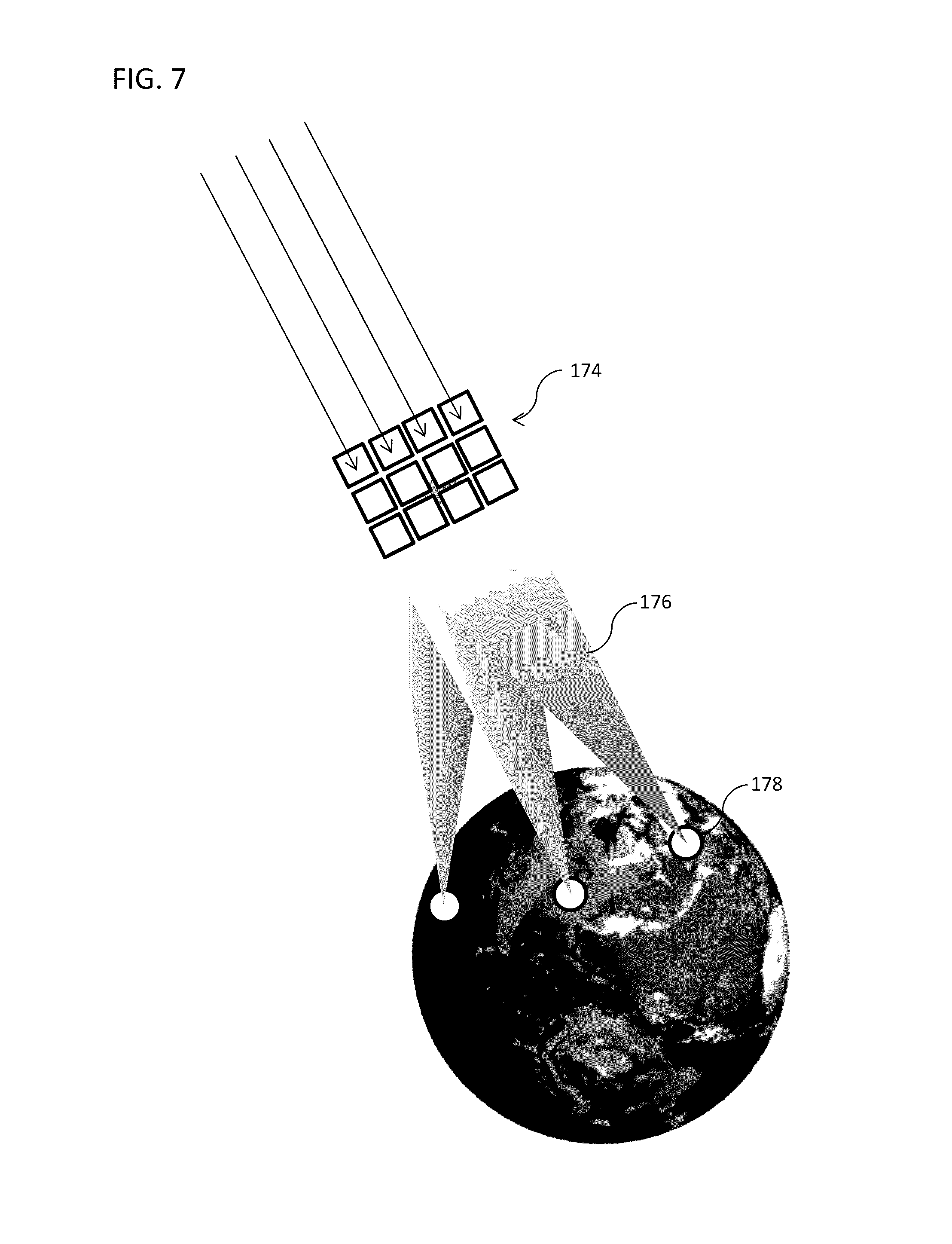
[0032] FIG. 7 conceptually illustrates dynamic power allocation from a large-scale space-based solar power system, according to one embodiment.
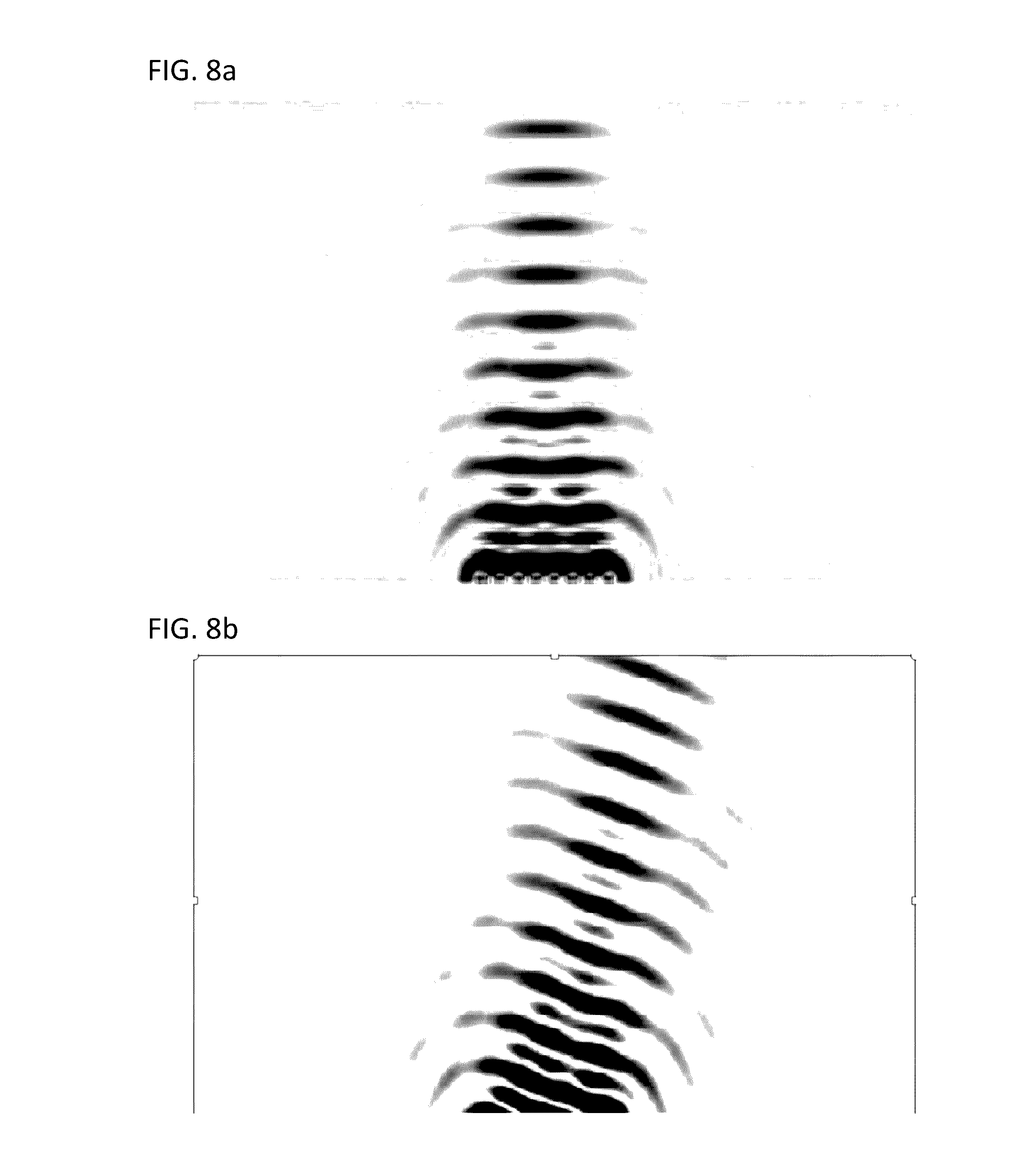
[0033] FIGS. 8a and 8b conceptually illustrate electronic beam steering using relative phase offset between elements of a phased array, according to one embodiment.
[0034] FIG. 9a conceptually illustrates a large-scale space-based solar power station and a compactable satellite module in a deployed configuration, according to embodiments.
[0035] FIG. 9b conceptually illustrates a retracted compactable satellite module, according to FIG. 9a in a retracted configuration.
[0036] FIG. 10 conceptually illustrates a compactable satellite module having a biaxial folding configuration, according to embodiments.
[0037] FIG. 11 provides images of the compaction of a membrane using the compaction technique of FIG. 10.
[0038] FIGS. 12a to 12d conceptually illustrate a cross-sectional view of a compactable satellite module having a slip folding and wrapping configuration, according to embodiments.
[0039] FIG. 13 conceptually illustrates a perspective view of a compactable satellite module having a slip folding and wrapping configuration, according to embodiments.
[0040] FIG. 14 provides images of the compaction of a membrane using the compaction technique of FIG. 13.
[0041] FIG. 15 conceptually illustrates a boom deployment mechanism for a compactable satellite module, according to embodiments.
[0042] FIG. 16 conceptually illustrates a spin deployment mechanism for a compactable satellite module, according to embodiments.
DETAILED DESCRIPTION
[0043] Turning now to the drawings, large-scale space-based solar power (SBSP) stations in accordance with various embodiments of the invention are illustrated. In many embodiments, the SBSP systems include arrays of independent satellite modules each incorporating arrays of independent solar electric power generation tiles. In several embodiments, the power generation tiles are each formed incorporating independent photovoltaic cells, power transmitters, and control circuits. The satellite modules and power generation tiles may be formed from compactible structures according to some embodiments. Methods for deploying, stabilizing, operating and constructing such large-scale space-based solar power systems in accordance with a number of embodiments of the invention are also described.
[0044] A large-scale space-based solar power station is a modular space-based construct that can be formed from a plurality of independent satellite modules placed into orbit within an orbital formation such that the position of each satellite module relative to each other is known. Each of the satellite modules can include a plurality of power generation tiles that capture solar radiation as electrical current and use the current to transmit the energy to one or more remote receivers using power transmitters. In many instances, the transmissions are generated using microwave power transmitters that are coordinated to act as a phased- and/or amplitude array capable of generating a steerable beam and/or focused beam that can be directed toward one or more remote receivers. In other embodiments, any of a variety of appropriate power transmission technologies can be utilized including (but not limited to) optical transmitters such as lasers.
[0045] Embodiments relate to lightweight space structures used to construct the modular elements of the solar power station. Some lightweight space structures are used in the construction of the power generation tiles and/or satellite modules and may incorporate movable elements that allow the lightweight space structure to be compacted prior to deployment to reduce the area or dimensional length, height and/or width of the power generation tiles and/or satellite modules prior to deployment. The space structures may be made of any number, size and configuration of movable elements, and the elements may be configured to compact according to any suitable compacting mechanism or configuration, including one or two-dimensional compacting using, among others, z-folding, wrapping, rolling, fan-folding, double z-folding, Miura-ori, slip folding, wrapping, and combinations thereof. Some embodiments of movable elements are interrelated by hinges, such as, frictionless, latchable, ligament, and slippage hinges, among others. Some embodiments of structures are pre-stressed and/or provided with supportive frameworks to reduce out-of-plane macro- and micro-deformation of the lightweight structures. Structures and modules may include dynamic stabilizing movement (e.g., spinning) during deployment and/or operation. Deployment mechanisms to deploy the compactible lightweight structures into a deployed operational state may be incorporated into or associated with embodiments of the lightweight structures. Some deployment mechanisms may include (but are not limited to) expansive boom arms, centrifugal force mechanisms such as tip masses or module self-mass, among others.
[0046] Large-scale spaced-based solar power stations according to many embodiments utilize a distributed approach to capture solar radiation, and to use the energy thus captured to operate power transmitters, which transmit power to one or more remote receivers (e.g., using laser or microwave emissions). The satellite modules of the solar power station can be physically independent structures, each comprising an independent array of power generation tiles. The satellite modules are each placed into a specified flying formation within an array of such satellite modules in a suitable orbit about the Earth. The position of each of the independent satellite modules in space within the orbital array formation is controllable via a combination of station-keeping thrusters and controlled forces from absorption, reflection, and emission of electromagnetic radiation, as well as guidance controls. Using such controllers each of the independent satellite modules may be positioned and maintained within the controlled orbital array formation relative to each of the other satellite modules so that each satellite module forms an independent modular element of the large-scale space-based solar power station. The solar radiation received by each of the power generation tiles of each of the independent satellite module is utilized to generate electricity, which powers one or more power transmitters on each of the power generation tiles. Collectively, the power transmitters on each of the power generation tiles can be configured as independent elements of a phased and/or amplitude-array.
[0047] The power generation tiles and/or satellite modules may also include separate electronics to process and exchange timing and control information with other power generation tiles and/or satellite modules within the large-scale space-based solar power station. In many implementations, the separate electronics form part of an integrated circuit that possesses the ability to independently determine a phase offset to apply to a reference signal based upon the position of an individual tile and/or transmitter element. In this way, coordination of a phased array of antennas can be achieved in a distributed manner.
[0048] In embodiments of the distributive approach, different array elements of the phased array may be directed to transmit power with different transmission characteristics (e.g., phase) to one or more different remote power receiving collectors (e.g., ground based rectenna). Each satellite module of power generation tiles, or combinations of power generating tiles across one or more satellite modules, may thus be controlled to transmit energy to a different power receiving collector using the independent control circuitry and associated power transmitters.
[0049] A photovoltaic cell (PV) refers to an individual solar power collecting element on a power generation tile in a satellite module. The PV includes any electrical device that converts the energy of light directly into electricity by the photovoltaic effect including elements made from polysilicon and monocrystalline silicon, thin film solar cells that include amorphous silicon, CdTe and CIGS cells, multijunction cells, perovskite cells, organic/polymer cells, and various alternatives thereof.
[0050] A power transmitter or radiator refers to an individual radiative element on a power generation tile in a satellite module and its associated control circuitry. A power transmitter can include any device capable of converting power in the electrical current generated by the PV to a wireless signal, such as microwave radiation or light, including (but not limited to) a laser, a klystron, a traveling-wave tube, a gyrotron, or suitable transistor and/or diode. A power transmitter may also include suitable transmissive antennas, such as, dipole, patch, helical or spherical antennas, among others.
[0051] A phased array refers to an array of power transmitters in which the relative phases of the respective signals feeding the power transmitters are configured such that the effective radiation pattern of the power emission of the array is reinforced in a desired emission direction and suppressed in undesired directions. Phased arrays in accordance with embodiments may be dynamic or fixed, active or passive.
[0052] An orbital array formation refers to any size, number or configuration of independent satellite modules being flown in formation at a desired orbit in space such that the position of the satellite modules relative to each other is known such that power generation tiles on each of the satellite modules within the formation serves as an array element in the phased array of the solar power station.
[0053] A power generation tile refers to an individual solar power collecting and transmitting element in the phased array of the large-scale space-based solar power station. In many embodiments a power generation tile is a modular solar radiation collector, converter and transmitter that collects solar radiation through at least one photovoltaic cell disposed on the tile, and uses the electrical current to provide power to at least one power transmitter collocated on the same tile that transmits the converted power to one or more remote power receiving collectors. Many of the power generation tiles incorporated within a space-based solar power station include separate control electronics independently control the operation of the at least one power transmitter located on the power generation tile based upon timing, position, and/or control information that may be received from other tiles and/or other modules within the large-scale space-based solar power station. In this way, the separate control electronics can coordinate (in a distributed manner) the transmission characteristics of each of the power generation tiles form a phased array. Each power generation tile may also include other structures such as radiation collectors for focusing solar radiation on the photovoltaic, thermal radiators for regulating the temperature of the power generation tile, and radiation shielding, among other structures.
[0054] A satellite module refers to an array of power generation tiles collocated on a single integral space structure. The space structure of the satellite module may be a compactable structure such that the area occupied by the structure may be expanded or contracted depending on the configuration assumed. The satellite modules may include two or more power generation tiles. Each power generation tile may include at least one solar radiation collector and power transmitter. As discussed above, each of the power generation tiles may transmit power and may be independently controlled to form an array element of one or more phased arrays formed across the individual satellite module or several such satellite modules collectively. Alternatively, each of the power generation tiles collocated on a satellite module may be controlled centrally.
[0055] A lightweight space structure refers to integral structures of movably interrelated elements used in the construction of the power generation tiles and/or satellite modules that may be configurable between at least packaged and deployed positions wherein the area and or dimensions of the power generation tiles and/or satellite modules may be reduced or enlarged in at least one direction. The lightweight space structures may incorporate or be used in conjunction with deployment mechanisms providing a deploying force for urging the movable elements between deployed and compacted configurations.
[0056] A large-scale space-based solar power station or simply solar power station refers to a collection of satellite modules being flown in an orbital array formation designed to function as one or more phased arrays. In embodiments the one or more phased arrays may be operated to direct the collected solar radiation to one or more power receiving collectors.
[0057] Transmission characteristics of a power generation tile refer to any characteristics or parameters of the power transmitter of the power generation tile associated with transmitting the collected solar radiation to a power receiving collector via a far-field emission. The transmission characteristics may include, among others, the phase and operational timing of the power transmitter and the amount of power transmitted.
Structure of Large-Scale Space-Based Solar Power Station
[0058] A large-scale space-based solar power station including a plurality of satellite modules positioned in an orbital array formation in a geosynchronous orbit about the Earth in accordance with embodiments of the invention is illustrated in FIG. 1. The large-scale space-based solar power station 100 includes an array of independent satellite modules 102. The solar power station 100 is configured by placing a plurality of independent satellite modules 102 into a suitable orbital trajectory in an orbital array formation 104, according to one embodiment. The solar power station 100 may include a plurality of such satellite modules 1A through NM. In one embodiment, the satellite modules 1A through NM are arranged in a grid format as illustrated in FIG. 1. In other embodiments, the satellite modules are arranged in a non-grid format. For example, the satellite modules may be arranged in a circular pattern, zigzagged pattern or scattered pattern. Likewise, the orbit may be either geosynchronous 106, which is typically at an altitude of 35,786 km above the Earth, or low Earth 108, which is typically at an altitude of from 800 to 2000 km above the Earth, depending on the application of the solar power station. As can readily be appreciated, any orbit appropriate to the requirements of a specific application can be utilized by a space-based solar power station in accordance with various embodiments of the invention.
[0059] In embodiments, the satellite modules in the solar power station are spatially separated from each other by a predetermined distance. By increasing the spatial separation, the maneuverability of the modules in relation to each other is simplified. As discussed further below, the separation and relative orientation of the satellite modules can impact the ability of the power generation tile on each of the satellite modules to operate as elements within a phased array. In one embodiment, each satellite module 1A through NM may include its own station keeping and/or maneuvering propulsion system, guidance control, and related circuitry. Specifically, as illustrated in FIG. 2, each of the satellite modules 102 of the solar power station 100 may include positioning sensors to determine the relative position 110 of the particular satellite module 1A through NM in relation to the other satellite modules 1A to NM, and guidance control circuitry and propulsion system to maintain the satellite module in a desired position within the arbitrary formation 104 of satellite modules during operation of the solar power station. Positioning sensors in accordance with many embodiments can include the use of external positioning data from global positions system (GPS) satellites or international ground station (IGS) network, as well as onboard devices such as inertial measurement units (e.g., gyroscopes and accelerometers), and combinations thereof. In several embodiments, the positioning sensors can utilize beacons that transmit information from which relative position can be determined that are located on the satellite modules and/or additional support satellites. The guidance control and propulsion system may likewise include any suitable combination of circuitry and propulsion system capable of maintaining each of the satellite modules in formation in the solar power station array 104. In many embodiments the propulsion system may utilize, among others, one or more of chemical rockets, such as biopropellant, solid-fuel, resistojet rockets, etc., electromagnetic thrusters, ion thrusters, electrothermal thrusters, solar sails, etc. Likewise, each of the satellite modules may also include attitudinal or orientational controls, such as, for example, reaction wheels or control moment gyroscopes, among others.
[0060] In many embodiments, as illustrated in FIG. 3, each satellite module 1A through NM of the solar power station 100 comprises a space structure comprised of one or more interconnected structural elements 111 having one or more power generation tiles 112 collocated thereon. Specifically, each of the satellite modules 1A through NM is associated with an array of power generation tiles 112 where each of the power generation tiles of the array each independently collect solar radiation and covert it to electric current. Power transmitters convert the electrical current to a wireless power transmission that can be received by a remote power receiving station. As discussed above, one or more power transmitters on each of a set of power generation tiles can be configured as an element in one or more phased arrays formed by collections of power generation tiles and satellite modules of the overall solar power station. In one embodiment, the power generation tiles in the satellite module are spatially separated from each other by a predetermined distance. In other embodiments, the construction of the satellite modules is such that the power generation tiles are separated by distances that can vary and the distributed coordination of the power generation tiles to form a phased array involves the control circuitry of individual power transmitters determining phase offsets based upon the relative positions of satellite modules and/or individual power generation tiles.
[0061] Power generation tiles 112 according to many embodiments include a multicomponent structure including a photovoltaic cell 113, a power transmitter 114, and accompanying control electronics 115 electrically interconnected as required to suit the needs of the power transmission application. As illustrated in FIG. 4a, in some embodiments photovoltaic cells 113, may comprise a plurality of individual photovoltaic elements 116 of a desired solar collection area that may be interconnected together to produce a desired electrical current output across the power generation tile. Some power transmitters 114 include one or more transmission antennas, which may be of any suitable design, including, among others, dipole, helical and patch. In the illustrated embodiment, a conventional patch antenna 114 incorporating a conductive feed 117 to conductively interconnect the RF power from the control electronics 115 to the antenna 114. As can readily be appreciated the specific antenna design utilized is largely dependent upon the requirements of a specific application. Some power transmitters 114 are physically separated from one or both of the photovoltaic cell 113 and/or the control electronics 115 such as by fixed or deployable spacer structures 118 disposed therebetween. Some control electronics 115 may include one or more integrated circuits 119 that may control some aspect of the power conversion (e.g., to a power emission such as collimated light or an radio frequency (RF) emission such as microwave radiation), movement and/or orientation of the satellite module, inter- and intra-satellite module communications, and transmission characteristics of the power generation tile and/or satellite module. Further conductive interconnections 120 may connect the control electronics 115 to the source power of the photovoltaic cell 113. Each of the power generation tiles may also include thermal radiators to control the operating temperature of each of the power generation tiles.
[0062] In some embodiments, the PV 113 is a multi-layer cell, as illustrated in FIG. 4b, incorporating at least an absorber material 113' having one or more junctions 113'' disposed between a back contact 121 on a back side of the absorber material and a top radiation shield 122 disposed on the surface of the absorber material in the direction of the incident solar radiation. The PV may include any electrical device that converts the energy of light directly into electricity by the photovoltaic effect including elements made from polysilicon and monocrystalline silicon, thin film solar cells that include amorphous silicon, CdTe and CIGS cells, multijunction cells, perovskite cells, organic/polymer cells, and various alternatives thereof. In some embodiments the made from a thin film of GaInP/GaAs that is matched to the solar spectrum. Radiation shielding may include a solar radiation transparent material such as SiO.sub.2, among others. The back contact may be made of any suitable conductive material such as a conductive material like aluminum, among others. The thickness of the back contact and top radiation shield may be of any thickness suitable to provide radiation shielding to the PV. Additional structures may be provided around the PV to increase the efficiency of the absorption and operation of the device including, for example, one or more concentrators that gather and focus incoming solar radiation on the PV, such as a Cassegrain, parabolic, nonparabolic, hyperbolic geometries or combinations thereof. The PV may also incorporate a temperature management device, such as a radiative heat sink. In some embodiments the temperature management device is integrated with the control electronics and may be configured to control the operating temperature of the PV within a range of from .about.150 to 300 K.
[0063] In a number of embodiments, the power transmitters that are components of power generation tiles are implemented using a combination of control circuitry and one or more antennas. The control circuitry can provide the power generation tile with the computational capacity to determine the location of the power generation tile antenna(s) relative to other antennas within the satellite module and/or the solar power station. As can readily be appreciated, the relative phase of each element within a phased array is determined based upon the location of the element and a desired beam direction and/or focal point location. The control circuitry on each power generation tile can determine an appropriate phased offset to apply to a reference signal using a determined location of the power generation tile antenna(s) and beam-steering information. In certain embodiments, the control circuitry receives position information for the satellite module and utilizes the position information to determine the location of the power generation tile antenna(s) and determine a phase offset to apply to a reference signal. In other embodiments, a central processor within a satellite module can determine the locations of antennas on power generation tiles and/or phase offsets to apply and provides the location and/or phase offset information to individual power generation tiles.
[0064] In many embodiments, the positional information of each tile is received from partially redundant systems, such as, but not limited to, gyroscopes, accelerometers, electronic ranging radar, electronic positioning systems, phase and/or timing information from beacons, as well as employing a priori knowledge from system steering and flight control commands. In several embodiments, electronic systems are located on the ground, and/or in space on satellites deployed for this purpose (and, possibly, other purposes, e.g. in the case of using GPS satellites).
[0065] In a number of embodiments, position information may be relayed in a hierarchical fashion between modules, panels and/or tiles within the space-based solar power station, such that a central processing unit relays positional information such as location and orientation of the entire space-based solar power station with respect to a ground station and/or other suitable known locations to modules within the system. The relayed information can be expressed as an absolute and/or differential location(s), and/or orientation(s) as appropriate to the requirements of specific applications. In a similar fashion, the location and/or orientation of each module with respect to the center of the space-based solar power station or other suitable reference point can be determined at each module using processes similar to those outlined above. Furthermore, going down a hierarchical level, the position and orientation information of individual panels and tiles can be determined in a similar fashion. The entirety or any useful part of this information can be used at the tile-level, the panel-level, the module-level, the system-level and/or any combination thereof to control the phase and/or amplitude of each tile radiator to form a beam or focal spot on the ground. The aggregate computational power of the computational resources of each tile, panel and/or module can be utilized since each tile (and/or panel or module) can utilize its local computational power available from a DSP, microcontroller or other suitable computational resource to control its operation such that the system in aggregate generates the desired or close-to desired beam and/or focused transmission.
[0066] In various embodiments, as illustrated conceptually in FIG. 4c, power generation tile control circuitry can be implemented using one or more integrated circuits. An integrated circuit 123 can include an input/output interface 124 via which a digital signal processing block 125 can send and receive information to communicate with other elements of a satellite module, which typically includes a processor and/or memory configured by a control application. In certain embodiments, the digital signal processing block 125 receives location information (see discussion above) that can be utilized to determine the location of one or more antennas. In many embodiments, the location information can include a fixed location and/or one or more relative locations with respect to a reference point. The digital signal processing block can utilize the received location information and/or additional information obtained from any of a variety of sensors including (but not limited to) temperature sensors, accelerometers, and/or gyroscopes to determine the position of one or more antennas. Based upon the determined positions of the one or more antennas, the digital signal processing block 125 can determine a phase offset to apply to a reference signal 126 used to generate the RF signal fed to a specific antenna. In the illustrated embodiment, the integrated circuit 500 receives a reference signal 126, which is provided to an RF synthesizer 127 to generate an RF signal having a desired frequency. The RF signal generated by the RF synthesizer 127 is provided to one or more phase offset devices 128, which are configured to controllably phase shift the RF signal received from the RF synthesizer. The digital signal processing block 125 can generate control signals that are provided to the phase offset device(s) 128 to introduce the appropriate phase shifts based upon the determined location(s) of the one or more antennas. In many embodiments, the amplitude of the generated signal can be modulated and/or varied alone or in conjunction with the phase appropriately upon the determined locations to form the power beam and/or focused transmission. The amplitude can be modulated in variety of ways such as at the input of a power amplifier chain via a mixer or within an amplifier via its supply voltage, an internal gate or cascade biasing voltage. As can readily be appreciated, any of a variety of techniques appropriate to the requirements of a specific application can be utilized to amplitude modulate an RF signal in accordance with various embodiments of the invention. The phase shifted RF signals can then be provided to a series of amplifiers that includes a power amplifier 129. While the entire circuit is powered by the electric current generated by the PV component(s) of the power generation tile, the power amplifier is primarily responsible for converting the DC electric current into RF power that is transmitted via the RF signal. Accordingly, the power amplifier increases the amplitude of the received phase shifted RF signal and the amplified and phase shifted RF signal is provided to an output RF feed 130 connected to an antenna. In many embodiments, the RF signal generated by the RF synthesizer is provided to an amplifier 131 and distributed to the control circuitry of other tiles. The distribution of reference signals between tiles in a module in accordance with various embodiments of the invention is discussed further below.
[0067] Although specific integrated circuit implementations are described above with reference to FIG. 4c, power generation tile control circuitry can be implemented using any of a variety of integrated circuits and computing platforms in accordance with various embodiments. Furthermore, satellite modules can be implemented without providing computational capabilities on each power generation tile and/or without utilizing the computational capabilities of a power generation tile to determine locations and/or phase shifts for the purposes of generating an RF signal to feed a power generation tile antenna.
[0068] In many embodiments, as illustrated conceptually in FIG. 5, a plurality of power generation tiles 112 on each satellite module may each form a panel 160 of a modular phased array 162 incorporating at least self-contained, collocated photovoltaics, power transmitters and control electronics within each power generation tile. The control electronics may allow for wire or wireless communications between the individual power generation tiles for the exchange of timing and control information. The array of control electronics may also allow for the exchange of control and timing formation with other satellite modules. Collocation of at least the power collection, far-field conversion, and transmission elements on each modular power generation tile allows for the each power generation tile to operate as an independent element of the phased array without inter- and intra- module power wiring.
[0069] In one embodiment, the power generation tiles and/or satellite modules may include other related circuitry. The other circuitry may include, among others, circuitry to control transmission characteristics of the power generation tiles, thermal management, inter or intra-module communications, and sensors to sense physical parameters, such as orientation, position, etc. The control circuitry may control transmission parameters such as phase and timing information such that the arrays of power generation tiles across each module and across the solar power station may be operated as independent array elements of one or more phased arrays. The sensors may include gyroscopes, GPS or IGS devices to estimate position and orientation, and thermocouples to estimate the temperature on the power generation tiles.
[0070] In one embodiment, the circuits for controlling transmission characteristic parameters may be collocated on the several power generation tiles or satellite modules and may control each transmitter of each power generation tile independently or in a synchronized manner such that the tiles operate as one or more element of one or more phased arrays. Reference signals (e.g., phase and timing) that can be used to synchronize the operation of the power generation tiles as a phased array may be generated locally on each power generation tile or satellite module and propagated via wired or wireless intra and inter-module communications links, or may be generated centrally from a single source on a single satellite module and propagated via wired or wireless intra and/or inter-module communications links across each of the satellite modules and power generation tiles. In addition, one or multiple timing reference signals may be generated from outside the space-based solar power station system such as one or more satellites flying in close proximity or even in different orbits; as well as from one or more ground stations.
[0071] Each power generation tile or satellite module may be operated independently or collectively as an element in a phased array. Entire or most operations associated with each individual power generation tile may be collocated on each of the power generation tiles or collectivized within the satellite module on which the power generation tiles are collocated, or across multiple satellite modules. In one embodiment, a central reference signal is generated and deviation (e.g., phase) from such reference signal is determined for each power generation tile array element of the phased array. By propagating a central reference signal from the reference signal, higher levels of control abstraction can be achieved to facilitate simpler programming for many operations of the phased array.
[0072] In some embodiments, each power generation tile of each satellite module may be the same or different. The number of distinct combinations of photovoltaic cells, transmission modules and control electronics may be as large as the number of power generation tiles in the satellite modules. Further, even where each of the power generation tiles on a satellite module are the same, each of the satellite modules 1A through NM or a group of satellite modules may have different solar radiation collection or transmission characteristics or may have arrays of power generation tiles of different sizes, shapes and configurations.
[0073] In embodiments, the solar power station is designed as a modular phased array where the plurality of satellite modules and power generating tiles located thereon form the array elements of the phased array. For this purpose, each of the satellite modules may be designed to be physically compatible with conventional launch vehicles although the achieved power generation of the phased array of the solar power station may exceed conventional space-based solar power satellites in many respects. Taking advantage of the increased performance, the solar power station phased array of the embodiment may include smaller payload size and overall array size to obtain equal or better power generation compared to conventional space-based solar power satellites. Alternatively, the size of the overall solar power station may be reduced compared to solar platforms in conventional solar power satellites while achieving comparable results.
[0074] In order to match the power generation of a conventional solar power satellite without increasing platform size or weight, the power collection, transmission and control logic for the individual power generation tiles is preferably collocated within each of the power generation tiles or within the satellite module on which the power generation tiles are collocated thus eliminating the need for intra- or inter-module communications, wiring or structural interconnection. In one embodiment, much of the power transmission control logic is a single collection of functions common to all or most of the power generating tiles. In this embodiment, the conventional external intra- and inter- power generation tile infrastructure for the solar power station may be entirely eliminated thus reducing the power generated per weight unit (W/kg).
[0075] In one embodiment, the phased array of the solar power station including the satellite modules and power generation tiles replaces a conventional monolithic solar power satellite. The solar power stations includes N.times.N satellite modules, each module including power generation tiles of
M N 2 . ##EQU00001##
Table 1 lists example configurations of solar power stations according to embodiments replacing conventional solar power stations.
TABLE-US-00001 TABLE 1 SPS Configuration Parameters SPS Exemplary Phased Array Efficiency Standards Configuration W/kg Max Size System Performance* Solar Cell 35% Efficiency DC-Microwave 78% USEF 41 100 .times. 95 m Power Received 12 GW Conversion Collection 86% JAXA 98 3.5 km Power Received/Module 1.72 MW Efficiency Transmission 77% ESA 132 15 km Power Received Rectenna 1.34 GW Efficiency Atmospheric <2% Alpha 33 6 km Rectenna size: 6.65 km Absorption Overall 14% Modular Phased 2270 60 .times. 60 m Total mass 900000 kg Array According (avg: 100 g/m.sup.2) to Embodiments *Assuming a Solar Power Station having a 50 .times. 50 array of 60 .times. 60 m satellite modules in a geosynchronous orbit with a 1 GHz power transmission having a a/.lamda. = 0.5, and a solar irradiance of 1400 W/m.sup.2.
[0076] The Conventional SPS performance in Table 1 are taken from published literature. The Exemplary Phased Array System Performance in Table 1 are estimates and may differ based on the actual design parameters implemented.
[0077] The number of power generation tile array elements in each satellite module, and the number of satellite modules in the solar power station may be determined based on, among other factors, power requirements, payload restrictions, etc. A first factor for the size of an overall solar power station is the power to be generated at the power receiving rectenna. As illustrated in FIG. 6, in embodiments the power incident on the ground using a far-field RF emission can have a maximum power lobe (u.sub.max) that is dependent on factors including (but not limited to) the size of the array, the wavelength of the RF transmission, and the phase offset error tolerated within the phased array. For example, in embodiments of a 50.times.50 array of satellite modules in a solar power station formed by 60.times.60 m satellite modules a maximum power lobe of 926 W/m.sup.2 is estimated to be generate on the ground with a sidelobe level of 44 W/m.sup.2. The incident area of the maximum power lobe with a 1 GHz emission is estimated to have a diameter of 6.6 km, while the incident area is estimated to have a diameter of 2.8 km for a 2.4 GHz emission. From a power transmission point of view, the preferred number of elements in the phased array formed by a solar power station and the wavelength of the transmission will depend on the size of the receiving rectenna and/or array of receiving rectennas. In many embodiments it is desirable to have the maximum power lobe on the ground coextensive with the rectenna area.
[0078] In embodiments this limitation many also be overcome by dividing the power transmission output 176 of the solar power station 174 between different rectenna power receivers 178, as illustrated conceptually in FIG. 7. In many embodiments, different collections of elements (e.g., satellite modules and/or power generation tiles) forming part of the solar power station 174 may be configured into different phased arrays that may be simultaneously directed at different rectenna power receivers 178 on the ground thus potentially reducing the individual incident areas radiated by the solar power station. In some embodiments additional control circuitry is provided either within the satellite module or within each of the power generation tiles to allow for dynamic electronic steering of the transmission beam, either from the collective power generation tiles of a satellite module or from each power generation tile independently. In some embodiments the power steering circuitry may allow for the control of the relative timing (phase) of the various power transmitters on the power generation tile array elements, as illustrated conceptually in FIGS. 8a and 8b, such that each transmission beam may be redirected electronically at micro- and/or nano-second time scales. The power transmission from such dynamically steerable phased array on a solar power station allows for the entire phased array or portions thereof to be dynamically redirected in different directions dependent on demand at one or more rectenna power receivers. Embodiments of such dynamically directable phased arrays on power solar stations, may be used to redirect the power transmission in different directions at micro and nano-second time scales by electronic steering. Embodiments also allow for power transmissions to be dynamically distributed to various ground stations either simultaneously or sequentially based on instantaneous local demand. Power levels at each of such rectenna receivers may also be dynamically adjusted. Rapid time domain switching of power amongst rectenna receivers can also be used to control duty cycle and alleviate large scale AC synchronization issues with respect to an overall power grid.
[0079] A second factor that may constrain the number of array elements in any satellite module is the issue of payload size and weight. Current payload delivery technologies for geosynchronous orbits range from 2,000 to 20,000 kg. Accordingly, the limit to the size of any single satellite module is the actual lift capacity of available payload delivery vehicles. Based on an assumption of 100 g/m.sup.2 for the phased array satellite modules according to embodiments, a 60.times.60 m satellite module would have a weight of 360 kg, well within the limits of current delivery technologies. Larger modules could be produced provided they are within the lift capacity of available lift vehicles.
[0080] In some embodiments, satellite modules are compactable such that the size of the satellite module in one or more dimensions may be reduced during delivery to overcome payload space constraints and then expanded into its final operating configuration. As illustrated in FIGS. 9a and 9b, in many embodiments the solar power station 180 includes an array of satellite modules 182, each satellite module comprising a plurality of structural elements 184 that are movably interconnected such that the plurality of structural elements may be moved between at least two configurations: a deployed configuration (FIG. 9a) and a compacted configuration (9b), such that the ratio of the packaged volume to the material volume is larger in the deployed configuration when compared to the compacted or packaged configuration. In embodiments, the structural elements 184 may be hinged, tessellated, folded or otherwise interconnected 186 such that the structural elements can move in relation to each other between the compacted and deployed configurations. Each satellite module of a solar power station may be configured to compact to the same or different sizes. In addition, different compacting methods may be used to compact one or more satellite modules of a solar space station, including, among others, one and two-dimensional compaction structures. In some embodiments, one or a combination of z-folding, wrapping, rolling, fan-folding, double z-folding, Miura-ori, slip folding and symmetric wrapping may be used, among others.
[0081] In many embodiments the power generation tiles may have further compactible and expandable features and structures disposed thereon. In some embodiments of power generation tiles the photovoltaic cell and power transmitter may be movably interrelated through a compactable structure, such that when in a compacted or packaged configuration the elements of the power generating cell are compressed together to occupy a total volume lower than when in a deployed configuration. In some deployed configurations the photovoltaic cell and power transmitter are separated by a gap (e.g., to create a vertical offset therebetween). Embodiments of compactable structure include motorized interconnections and resilient members such as spring or tension arms that are bent or under compression, among others. Such compactable structures may also incorporate packaging techniques such as one or a combination of z-folding, wrapping, rolling, fan-folding, double z-folding, Miura-ori, slip folding and symmetric wrapping may be used, among others.
[0082] The power generation tiles and/or satellite modules may include other structures to enhance the collection of solar radiation or transmission of power from the power generation tiles and/or satellite modules. Embodiments of structures that may be incorporated into power generation tiles and/or satellite modules may include, among others, thermal radiators for controlling the thermal profile of the power generation tiles, light-collecting structures (e.g., radiators, reflectors and collectors) to enhance the efficiency of solar radiation collection to the photovoltaic cell, and radiation shielding to protect the photovoltaic cells, power transmitters and/or control electronics from space radiation. Such structures may also be independently compactible, between packaged and deployed configurations, as described above in relation to other elements of the power generation tiles.
[0083] A design for a satellite module or power generation tile may be applied to different satellite modules or power generation tiles. Other variables in the solar power station such as spatial distances, photovoltaics, power transmitter, control electronics and combinations with may be modified to produce a phased array with differing power collection and transmission characteristics. In this way, a diverse mix of solar power stations may be produced while maintaining the benefits of the modular solar power station described.
Compactable Space Structures
[0084] In many embodiments, the satellite modules of the solar power station employ compactible structures. Compactable structures allow for the satellite modules and/or power generation tiles to be packaged in a compacted form such that the volume occupied by the satellite module and/or power generation tiles can be reduced along at least dimension to allow for the satellite modules to fit within an assigned payload envelope within a delivery vehicle. Several exemplary embodiments of possible packaging schemes are provided, however, it should be understood that the packaging procedure and compactible structures may involve, among other procedures, using one and two-dimensional compaction techniques, including, one or a combination of z-folding, wrapping, rolling, fan-folding, double z-folding, Miura-ori, star folding, slip folding and wrapping.
[0085] In many embodiments a two-dimensional compacting technique may be utilized to package and deploy the satellite modules and/or power generation tiles. FIG. 10 provides a perspective view of a satellite module 290 with a plurality of power generation tiles 292, according to embodiments. The plurality of power generation tiles 292 in this embodiment are hinged together and tessellated into a Miura-ori folding pattern such that the satellite module is compacted biaxially along an X and Y axis. Although the hinges interconnecting the panels may be made of any suitable design, in one embodiment the hinged elements are interconnected by carbon fiber rods or other suitable support structure. Images of a membrane being folded in accordance with these embodiments are provided in FIG. 11.
[0086] In many embodiments a slip-wrapping compacting technique may be utilized to package and deploy the satellite modules and/or power generation tiles. FIGS. 12a to 12d provide cross-sectional views of the construction of embodiments of the slip-wrapping technique. As shown, in these embodiments two elongated elements 300 and 302 interconnected at a first end 304 and open at a second end 306 (FIG. 12a) are wrapped about a hub (FIG. 12b). Such wrapping causes one of the elongated elements 300 to slip along its longitudinal length with respect to the second elongated element 302 such that a gap 308 forms between the unconnected ends of the elements. A second set of such elongated elements 310 and 312 interconnected at one end 314 are then obtained by a 180.degree. rotation of the first set of elongated elements and the non-interconnected ends are then joined together 316 to form a single elongated element of an undulating configuration 318 interconnected at both ends 304 and 314 (FIG. 12c). The undulating strip thus formed may then be wrapped about a hub of a specified radius 320 that is no smaller than the minimum bend radius of the material of the elongated element thus reducing the dimensions of the satellite module biaxially in both an X and a Y axis (FIG. 12d).
[0087] Embodiments of a slip-wrap packing technique as applied to a compactible satellite module 350 are shown in a perspective view in FIG. 13. In one embodiment the satellite module is formed of a plurality of elongated structures 352 that are interconnected at two ends 354 and 356, but that are allowed to shear along their edges. During packaging the elongated structures are first folded with z-fold to form an elongated plurality of structures that are compacted along a first axis 358 orthogonal to the longitudinal axis 360 of the elongated structures. The compacted elongated structures are then wrapped about a hub with a radius 362 (which is selected to be no smaller than the minimum bend radius of the elongated structures of the satellite module) to further compact the strips along a second axis, thereby forming a fully compacted satellite module. Although a satellite module with an overall rectangular configuration are shown in FIGS. 12 and 13, it should be understood that the technique may be implemented with any configuration, number or shape of individual strip elements so long as they are joined at the edges and the edges are permitted to shear as described above. Images of a compactible structure using a diagonal z-fold in accordance with these embodiments are provided in FIG. 14. In this embodiment the deployed square of 0.5 m may be packaged into a cylindrical structure with a diameter of 10 cm and a height of 7 cm.
[0088] Using such techniques it is possible to significantly reduce the packaging volume of the satellite modules. In one exemplary embodiment where the compactible structures of a satellite module have a tile/panel thickness of 1 cm and a minimum bend radius of 10 cm, a satellite module with a deployed area of 60 m.times.60 m and being comprised of 30 such compactible structures would be compactible using the slip-wrap packaging technique into cylindrical package with a diameter of 5 m and a height of 2 m.
[0089] In many embodiments the number of compactible elements in each of the satellite modules in a solar space station may be the same or different and may contain one or more power generation tiles collocated thereon. One or more compacting techniques may be used in packaging the compactible elements of each of the satellite modules and the techniques use may also the same or different. In many embodiments the compacting techniques utilized to package the satellite modules prior to deployment reduce the packaging volume of the satellite module in at least one dimension such that the satellite module fits within the allowed payload volume of the selected delivery vehicle.
[0090] In many embodiments the power generation tiles may have further compactible and expandable features and structures disposed thereon. In some embodiments of power generation tiles the photovoltaic cell and power transmitter may be movably interrelated through a compactable structure, such that when in a compacted or packaged configuration the elements of the power generation tile are compressed together to occupy a total volume lower than when in a deployed configuration. In some deployed configurations the photovoltaic cell and power transmitter are separated by a gap (e.g., to create a vertical offset therebetween). Embodiments of compactable structure include motorized interconnections and resilient members such as spring or tension arms that are bent or under compression, among others. Such compactable structures may also incorporate packaging techniques such as one or a combination of z-folding, wrapping, rolling, fan-folding, double z-folding, Miura-ori, slip folding and symmetric wrapping may be used, among others.
[0091] In many embodiments deployment mechanisms are provided to deploy the compacted satellite modules (e.g., move the compactible elements of the satellite module from a compacted to a deployed configuration). In many embodiments an active or passive mechanism is interconnected with one or more portions of the compactible structures of the satellite module such that when activated the compacted structures of the satellite modules may be expanded into a deployed operational configuration.
[0092] In some embodiments a mechanically expandable member may be incorporated into the satellite module. An illustration of such a satellite module is provided in FIG. 15 where a satellite module 400 having a plurality of compactible structures 402 are disposed about a central hub 404. The compactible structures 402 are interconnected on at least one edge with a mechanically expandable member 406 such that as the mechanical member is urged outward the compactible structures are also expanded outward from the central hub. The expandable member may be motorized or may use stored energy, such as, compressed or bent expandable members, among others.
[0093] In many embodiments the compactible structures of the satellite module may be configured such that motion of the satellite module provides the expansive deployable force. An illustration of one such embodiment is provided in FIG. 16 where weighted elements 420 are attached between a central hub 422 and at least a portion of each of the compactible structures 424 of the satellite module 426 such that when the central hub of the satellite module is spun the centrifugal force of the spinning hub causes the weighted elements to move outward thereby expanding the compactible structures. In such embodiments the satellite module may be made to spin continuously to provide a stabilization force to the compactible structures.
[0094] Regardless of the mechanism chosen, in many embodiments the satellite module may be divided into any number and configuration of separate compactible structures with any number of hubs and deployment mechanisms (e.g., expandable members, weighted elements, etc.). In many embodiments the compactible structures are attached along at least two edges to more than one deployment mechanism such that more even expansion of the compactible structures may be obtained. In many embodiments, for example, multiple weights or expandable members may be attached to each of the compactible structures along multiple points or edges of the compactible structures. Some expandable members or weighted elements may be incorporated into the structure of the compactible structures. Many embodiments of deployment mechanisms may include deployment controls to controllably operate the compactible structures of the satellite modules so that the satellite modules are expanded into a deployed configuration when desired. Some embodiments of such deployment controls may be automated, such that the positioning or motion of the satellite hub automatically engages the deployment mechanism, such as, for example, by spinning the satellite module at a specified rate. Other embodiments may incorporate control circuits such that an external signal or command is required to activate the deployment mechanism. Such deployment controls may operate across an entire satellite module, may be disposed individually in each power generation tile, or a combination thereof.
[0095] While particular embodiments and applications of the present invention have been illustrated and described herein, it is to be understood that the invention is not limited to the precise construction and components disclosed herein and that various modifications, changes, and variations may be made in the arrangement, operation, and details of the methods and apparatuses of the present invention without departing from the spirit and scope of the invention as it is defined in the appended claims.
* * * * *
D00000
D00001
D00002
D00003
D00004
D00005
D00006
D00007
D00008
D00009
D00010
D00011
D00012

D00013

D00014
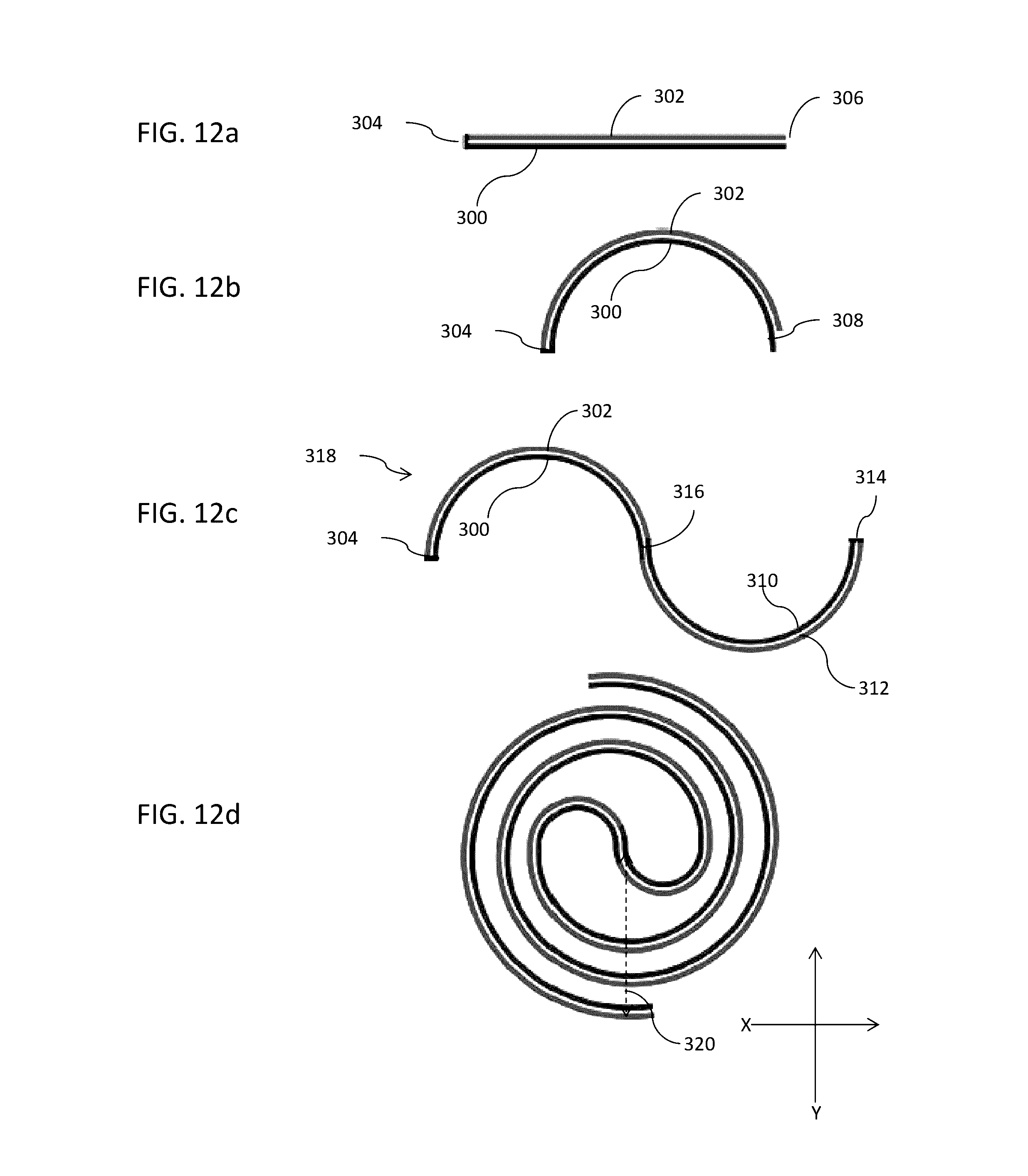
D00015
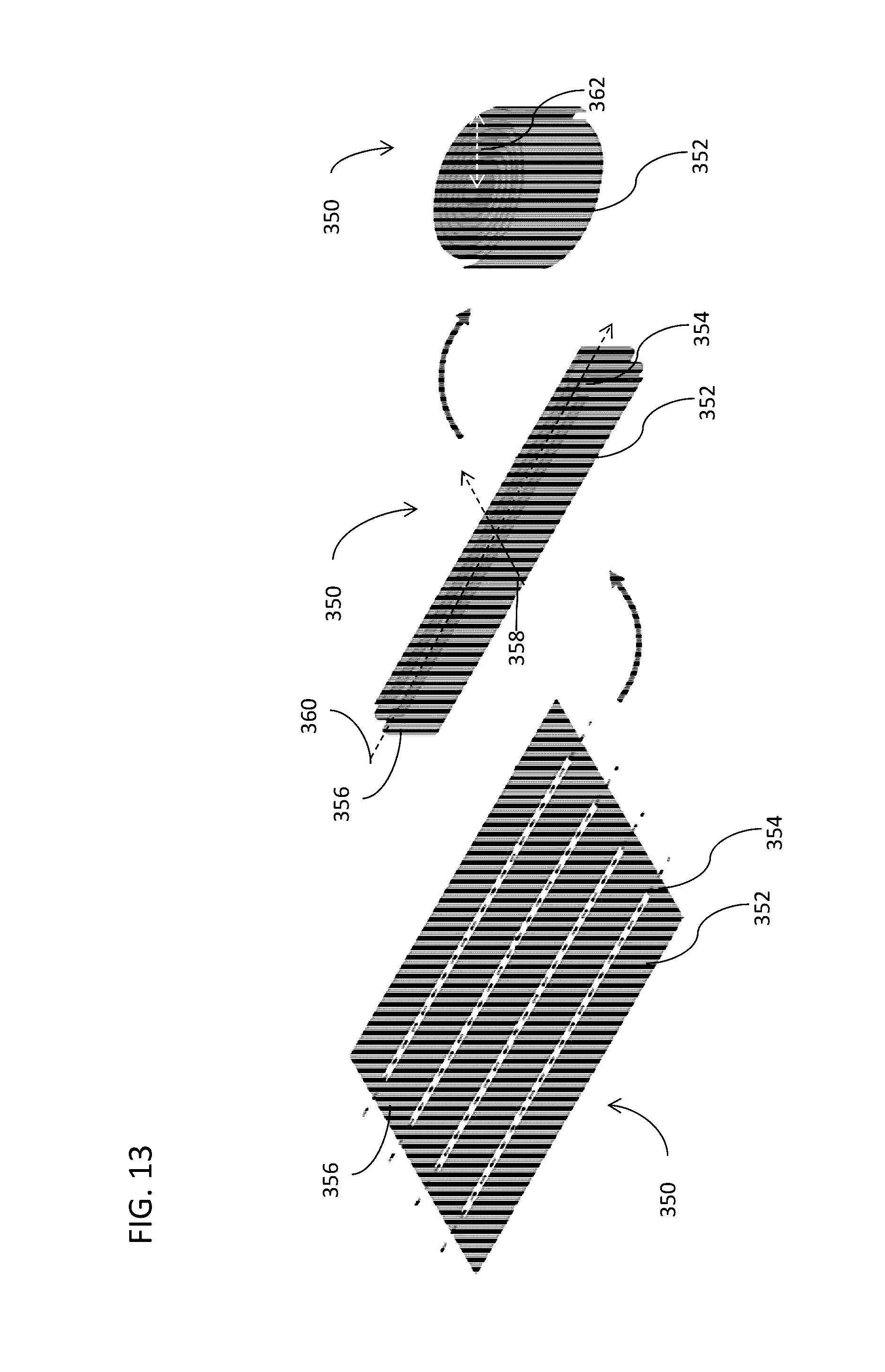
D00016
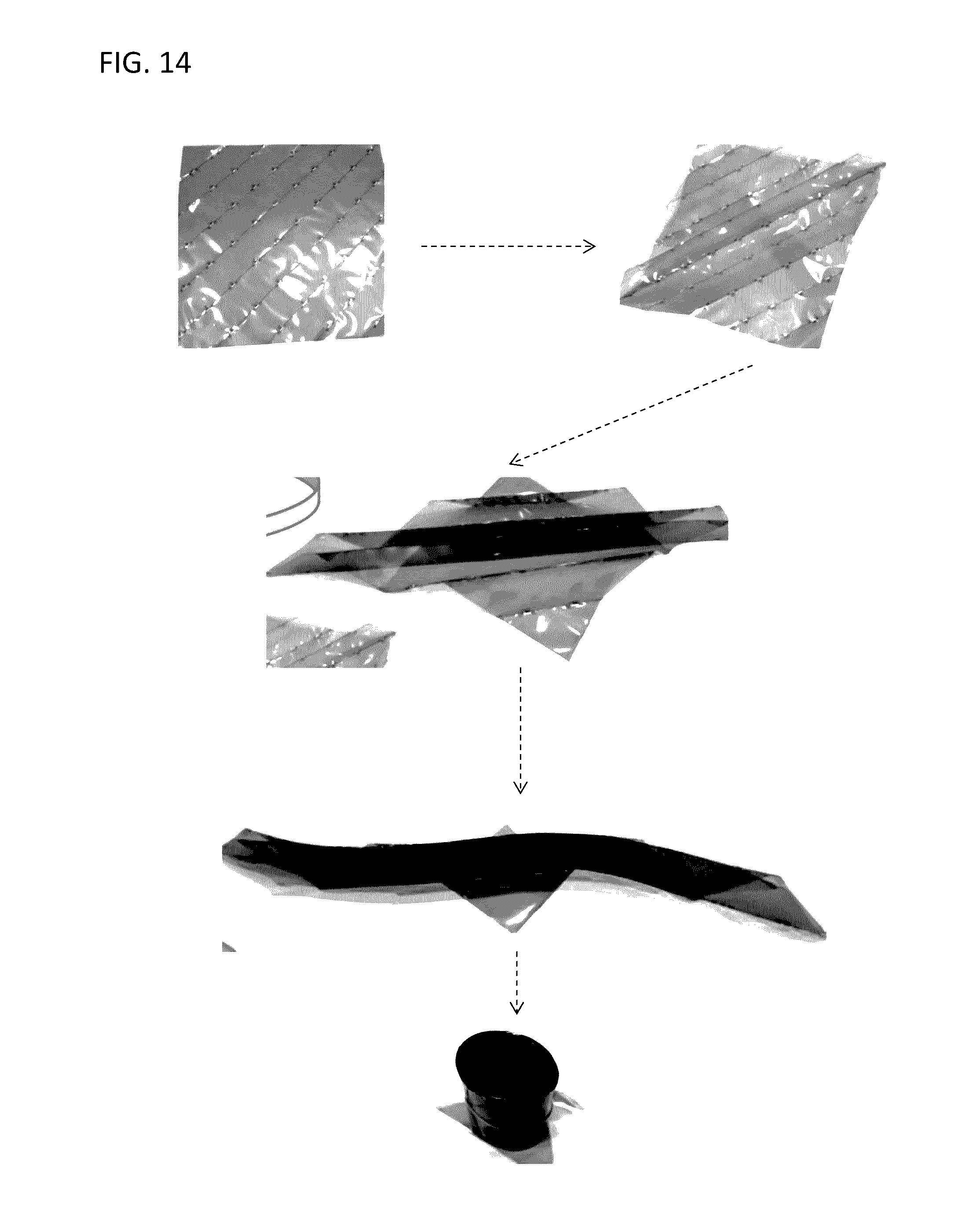
D00017

D00018
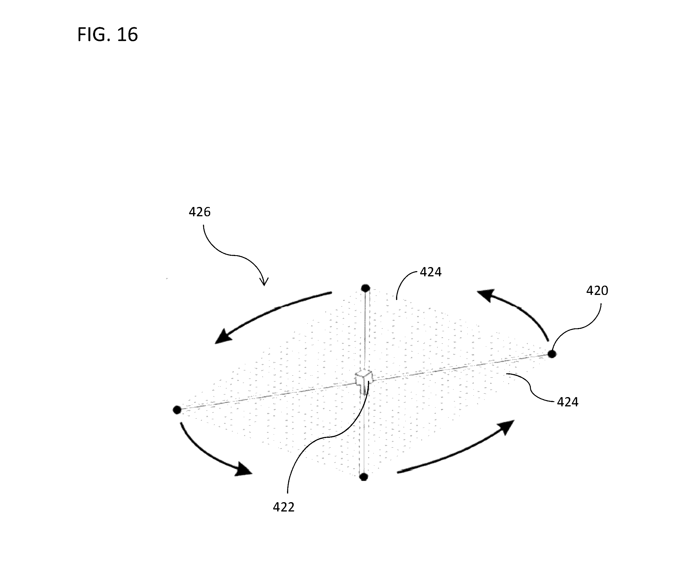

XML
uspto.report is an independent third-party trademark research tool that is not affiliated, endorsed, or sponsored by the United States Patent and Trademark Office (USPTO) or any other governmental organization. The information provided by uspto.report is based on publicly available data at the time of writing and is intended for informational purposes only.
While we strive to provide accurate and up-to-date information, we do not guarantee the accuracy, completeness, reliability, or suitability of the information displayed on this site. The use of this site is at your own risk. Any reliance you place on such information is therefore strictly at your own risk.
All official trademark data, including owner information, should be verified by visiting the official USPTO website at www.uspto.gov. This site is not intended to replace professional legal advice and should not be used as a substitute for consulting with a legal professional who is knowledgeable about trademark law.