Light Guide Plate, Backlight Module, And Display Device
GUO; Wei ; et al.
U.S. patent application number 14/646019 was filed with the patent office on 2016-12-29 for light guide plate, backlight module, and display device. This patent application is currently assigned to Shenzhen China Star Optoelectronics Technology Co., Ltd.. The applicant listed for this patent is SHENZHEN CHINA STAR OPTOELECTRONICS TECHNOLOGY CO., LTD., WUHAN CHINA STAR OPTPELECTRONICE TECHNOLOGY CO., LTD. Invention is credited to Wei GUO, Zhongjie LIU, Jie ZENG.
| Application Number | 20160377784 14/646019 |
| Document ID | / |
| Family ID | 53454686 |
| Filed Date | 2016-12-29 |


| United States Patent Application | 20160377784 |
| Kind Code | A1 |
| GUO; Wei ; et al. | December 29, 2016 |
LIGHT GUIDE PLATE, BACKLIGHT MODULE, AND DISPLAY DEVICE
Abstract
The present invention provides a light guide plate, a backlight module, and a display device. The light guide plate contains a platform of uniform thickness along an edge of the light guide plate for installing a flexible printed circuit (FPC). The platform contains a plurality of through openings for installing light emitting diodes (LEDs). The backlight module contains LEDs, a FPC, and the light guide plate. The FPC is configured on the platform. The LEDs are configured inside the openings. The display device contains the backlight module. The present invention enhances the reliable connection between the FPC and light guide plate, reduces the probability of coupling failure, and lower the manufacturing difficulty and cost.
| Inventors: | GUO; Wei; (Shenzhen, Guangdong, CN) ; ZENG; Jie; (Shenzhen, Guangdong, CN) ; LIU; Zhongjie; (Shenzhen, Guangdong, CN) | ||||||||||
| Applicant: |
|
||||||||||
|---|---|---|---|---|---|---|---|---|---|---|---|
| Assignee: | Shenzhen China Star Optoelectronics
Technology Co., Ltd. Shenzhen City, Guangdong CN |
||||||||||
| Family ID: | 53454686 | ||||||||||
| Appl. No.: | 14/646019 | ||||||||||
| Filed: | March 20, 2015 | ||||||||||
| PCT Filed: | March 20, 2015 | ||||||||||
| PCT NO: | PCT/CN2015/074687 | ||||||||||
| 371 Date: | May 20, 2015 |
| Current U.S. Class: | 362/612 |
| Current CPC Class: | G02B 6/0083 20130101; G02B 6/0068 20130101; G02B 6/0021 20130101; G02B 6/0028 20130101; G02B 6/002 20130101 |
| International Class: | F21V 8/00 20060101 F21V008/00 |
Foreign Application Data
| Date | Code | Application Number |
|---|---|---|
| Mar 3, 2015 | CN | 201510094538.8 |
Claims
1. A light guide plate comprising a platform of uniform thickness along an edge of the light guide plate for installing a flexible printed circuit (FPC) wherein the platform comprises a plurality of through openings for installing light emitting diodes (LEDs).
2. The light guide plate as claimed in claim 1, further comprising a blocking rim raised above the platform along an outer side of the openings which is adjacent to the edge of the light guide plate.
3. The light guide plate as claimed in claim 2, further comprising a slope along an inner side of the openings which is opposite to the outer side and is adjacent to a major region of the light guide plate, wherein the slope connects between the platform and the major region of the light guide plate; and the thickness of the platform is greater than that of the main region of the light guide plate.
4. The light guide plate as claimed in claim 2, wherein the blocking rim comprises a plurality of notches allowing extension of the FPC so as to facilitate wire layout.
5. The light guide plate as claimed in claim 1, wherein at least a side of the light guide plate that does not emit light is covered with a seal layer.
6. The light guide plate as claimed in claim 5, wherein the seal layer is a silk printing layer.
7. A backlight module comprising a plurality of LEDs, a FPC, and a light guide plate, wherein the light guide plate comprises a platform of uniform thickness along an edge of the light guide plate for installing the FPC; the platform comprises a plurality of through openings for installing the LEDs; the LEDs are configured inside the openings; and the FPC is configured on the platform.
8. The backlight module as claimed in claim 7, wherein the light guide plate further comprises a blocking rim raised above the platform along an outer side of the openings which is adjacent to the edge of the light guide plate.
9. The backlight module as claimed in claim 8, wherein the light guide plate further comprises a slope along an inner side of the openings which is opposite to the outer side and is adjacent to a major region of the light guide plate; the slope connects between the platform and the major region of the light guide plate; and the thickness of the platform is greater than that of the main region of the light guide plate.
10. The backlight module as claimed in claim 8, wherein the blocking rim comprises a plurality of notches allowing extension of the FPC so as to facilitate wire layout.
11. The backlight module as claimed in claim 7, wherein at least a side of the light guide plate that does not emit light is covered with a seal layer.
12. The backlight module as claimed in claim 11, wherein the seal layer is a silk printing layer.
13. The backlight module as claimed in claim 7, wherein the FPC is adhered to the platform.
14. The backlight module as claimed in claim 7, wherein the LEDs are welded to pads of the FPC.
15. A display device comprising a backlight module wherein the backlight module comprises a plurality of LEDs, a FPC, and a light guide plate; the light guide plate comprises a platform of uniform thickness along an edge of the light guide plate for installing the FPC; the platform comprises a plurality of through openings for installing the LEDs; the LEDs are configured inside the openings; and the FPC is configured on the platform.
16. The display device as claimed in claim 15, wherein the light guide plate further comprises a blocking rim raised above the platform along an outer side of the openings which is adjacent to the edge of the light guide plate.
17. The display device as claimed in claim 16, wherein the light guide plate further comprises a slope along an inner side of the openings which is opposite to the outer side and is adjacent to a major region of the light guide plate; the slope connects between the platform and the major region of the light guide plate; and the thickness of the platform is greater than that of the main region of the light guide plate.
18. The display device as claimed in claim 16, wherein the blocking rim comprises a plurality of notches allowing extension of the FPC so as to facilitate wire layout.
19. The display device as claimed in claim 15, wherein at least a side of the light guide plate that does not emit light is covered with a seal layer.
20. The display device as claimed in claim 19, wherein the seal layer is a silk printing layer.
Description
BACKGROUND OF THE INVENTION
[0001] 1. Field of the Invention
[0002] The present invention generally relates to display technology, and particularly relates to a light guide plate, a backlight module, and a display device.
[0003] 2. The Related Arts
[0004] In a display device, a backlight module is employed to provide sufficient and uniform illumination so that the display device is able to present images correctly. Light guide plate (LGP) is a one of the backlight module's components. A LGP is made of optical-grade acrylic or polycarbonate (PC), and a number of light dots are produced on the LGP by dot printing, injection molding, or hot pressing. The light dots interferes light beams' total reflection inside the LGP so that the light beams exit the LGP from a light emission face. By arranging the light dots into various densities and dimensions, the light emitted from the LGP can be uniformed.
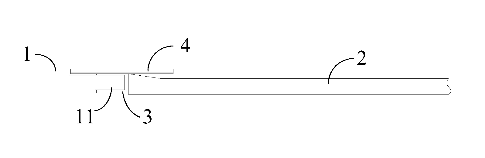
[0005] As shown in FIG. 1, an existing backlight module contains the following components: a plastic frame 1, a LGP 2, a number of light emitting diodes (LEDs) 3, and a flexible printed circuit (FPC) 4. Usually the LEDs 3 are welded to pads on the FPC 4 and they can be considered as a single component. As shown in FIG. 2, a number of support elements 11 are configured on the plastic frame 1, and the LEDs 3 are installed between neighboring support elements 11 by adhesion. Additionally, a slope is usually configured at the rims of the LGP 2 so as to reduce the thickness of a major region of the LGP 2. FPC 4 is installed on the LGP 2 also by adhesion to facilitate the LEDs 3's optical coupling a light incident face of the LGP 2.
[0006] As the plastic frame 1 is required to ben even thinner, the manufacturing of the protruding support elements is getting more difficult, and the stability of the product assembly is also compromised. Additionally, due to the slops on the LGP, the interface between the LGP and the FPC is reduced a line of contact. There can easily be relative motion between the LGP and the FPC, causing failure to the optical coupling.
SUMMARY OF THE INVENTION
[0007] The technical issue to be addressed by the present invention is to provide a light guide plate, a backlight module, and a display device so as to resolve the issues of manufacturing difficulty and inferior stability suffered by the prior art.
[0008] To address the technical issue, the present invention provides a light guide plate which contains a platform of uniform thickness along an edge of the light guide plate for installing a flexible printed circuit (FPC). The platform contains a number of through openings for installing light emitting diodes (LEDs).
[0009] The light guide plate further contains a blocking rim raised above the platform along an outer side of the openings which is adjacent to the edge of the light guide plate.
[0010] The light guide plate further contains a slope along an inner side of the openings which is opposite to the outer side and is adjacent to a major region of the light guide plate. The slope connects between the platform and the major region of the light guide plate. The thickness of the platform is greater than that of the main region of the light guide plate.
[0011] The blocking rim contains a number of notches allowing extension of the FPC so as to facilitate wire layout.
[0012] At least a side of the light guide plate that does not emit light is covered with a seal layer.
[0013] The seal layer is a silk printing layer.
[0014] To address the technical issue, the present invention also provides a backlight module which contains a number of LEDs, a FPC, and a light guide plate. The light guide plate contains a platform of uniform thickness along an edge of the light guide plate for installing the FPC, the platform contains a number of through openings for installing the LEDs. The LEDs are configured inside the openings. The FPC is configured on the platform.
[0015] The light guide plate further contains a blocking rim raised above the platform along an outer side of the openings which is adjacent to the edge of the light guide plate.
[0016] The light guide plate further contains a slope along an inner side of the openings which is opposite to the outer side and is adjacent to a major region of the light guide plate. The slope connects between the platform and the major region of the light guide plate. The thickness of the platform is greater than that of the main region of the light guide plate.
[0017] The blocking rim contains a number of notches allowing extension of the FPC so as to facilitate wire layout.
[0018] At least a side of the light guide plate that does not emit light is covered with a seal layer.
[0019] The seal layer is a silk printing layer.
[0020] The FPC is adhered to the platform.
[0021] The LEDs are welded to pads of the FPC.
[0022] To address the technical issue, the present invention further provides a display device which contains a backlight module. The backlight module contains a number of LEDs, a FPC, and a light guide plate. The light guide plate contains a platform of uniform thickness along an edge of the light guide plate for installing the FPC. The platform contains a number of through openings for installing the LEDs. The LEDs are configured inside the openings; and the FPC is configured on the platform.
[0023] The light guide plate further contains a blocking rim raised above the platform along an outer side of the openings which is adjacent to the edge of the light guide plate.
[0024] The light guide plate further contains a slope along an inner side of the openings which is opposite to the outer side and is adjacent to a major region of the light guide plate. The slope connects between the platform and the major region of the light guide plate. The thickness of the platform is greater than that of the main region of the light guide plate.
[0025] The blocking rim contains a number of notches allowing extension of the FPC so as to facilitate wire layout.
[0026] At least a side of the light guide plate that does not emit light is covered with a seal layer.
[0027] The seal layer is a silk printing layer.
[0028] The advantage of the present invention is that, with the through openings, the installation of LEDs to the light guide plate does not require a plastic frame, and there is no need to configured support elements on the plastic frame. All is required is to work out the openings on the light guide plate. The manufacturing difficulty and therefore cost are reduced. In addition, as the light guide plate has an enhanced integrity and robustness, the light guide plate provides superior structural strength and reliability when manufactured to a great dimension. Furthermore, the installation of FPC on the platform achieves a planar, rather than linear, contact between the FPC and the light guide plate, and the relative motion therebetween is as such avoided. The reliability of the connection between the FPC and the light guide plate is thereby enhanced and the steady positioning of the FPC is achieved, significantly reducing the probability of coupling failure.
BRIEF DESCRIPTION OF THE DRAWINGS
[0029] To make the technical solution of the embodiments according to the present invention, a brief description of the drawings that are necessary for the illustration of the embodiments will be given as follows. Apparently, the drawings described below show only example embodiments of the present invention and for those having ordinary skills in the art, other drawings may be easily obtained from these drawings without paying any creative effort. In the drawings:
[0030] FIG. 1 is a cross-sectional diagram showing a conventional backlight module around one of its edges;
[0031] FIG. 2 is a cross-sectional diagram showing a conventional backlight module around one of its edges;
[0032] FIG. 3 is a front-view diagram showing a light guide plate according to an embodiment of the present invention;
[0033] FIG. 4 is perspective diagram showing a corner of the light guide plate of FIG. 3;
[0034] FIG. 5 is a sectional diagram showing the light guide plate of FIG. 3;
[0035] FIG. 6 is a perspective diagram showing a corner of a backlight module according to an embodiment of the present invention;
[0036] FIG. 7 is a perspective diagram showing a back side of the back light module of FIG. 6; and
[0037] FIG. 8 is a sectional diagram showing the backlight module of FIG. 6.
DETAILED DESCRIPTION OF THE PREFERRED EMBODIMENTS
[0038] FIG. 3 is a front-view diagram showing a light guide plate 100 according to an embodiment of the present invention. FIG. 4 is perspective diagram showing a corner of the light guide plate 100 of FIG. 3. FIG. 5 is a sectional diagram showing the light guide plate 100 of FIG. 3.
[0039] The light guide plate 100 contains a platform 101 of uniform thickness along an edge of the light guide plate 100. The platform 101 is for the installation of a flexible printed circuit (FPC) and is configured with a number of through openings 102 where light emitting diodes (LEDs) are installed.
[0040] The installation of LEDs to the light guide plate 100 therefore does not require a plastic frame, and there is no need to configured support elements on the plastic frame. All is required is to work out the openings 102 on the light guide plate 100. The manufacturing difficulty and therefore cost are reduced. In addition, as the light guide plate 100 has an enhanced integrity and robustness, the light guide plate 100 provides superior structural strength and reliability when manufactured to a great dimension. Furthermore, the installation of FPC on the platform 101 achieves a planar, rather than linear, contact between the FPC and the light guide plate 100, and the relative motion therebetween is as such avoided. The reliability of the connection between the FPC and the light guide plate 100 is thereby enhanced and the steady positioning of the FPC is achieved, significantly reducing the probability of coupling failure.
[0041] As illustrated, alternatively, a blocking rim 104 can be configured on the light guide plate 100. A side of the openings 102 adjacent to the edge of the light guide plate 100 is referred to as the outer side, whereas an opposite side of the openings 102 is referred to as the inner side. The blocking rim 104 is raised above the platform 101 and is configured along the outer sides of the openings 102. The purpose of the blocking rim 104 is to provide fixation to the FPC from a lateral side so that its installation is even more stable. The blocking rim 104 contains a number of notches 106 allowing extension of FPC therethrough so as to facilitate wire layout.
[0042] Alternatively, the light guide plate 100 can further contains a slope 107.
[0043] The slope 107 is configured along the inner sides of the openings 102 and borders a main region 108 of the light guide plate 100. The platform 101 has a greater thickness than that of the main region 108 of the light guide plate 100. The platform 101 is configured only along the edge where the LEDs are to be arranged. The platform 101 joins to the main region 108 of the light guide plate 100 through the slope 107. The purpose of such design is to reduce the thickness of the light guide plate 100. Please note that the light guide plate 100 can be a planar one or a wedge-shaped one.
[0044] In addition, the various sides of the light guide plate 100 that do not emit light are covered with a seal layer. The seal layer can be a silk printing layer, such as white silk printing layer or black silk printing layer, to reflect or block light. The configuration of seal layers is applicable to the various light guide plates 100 described above.
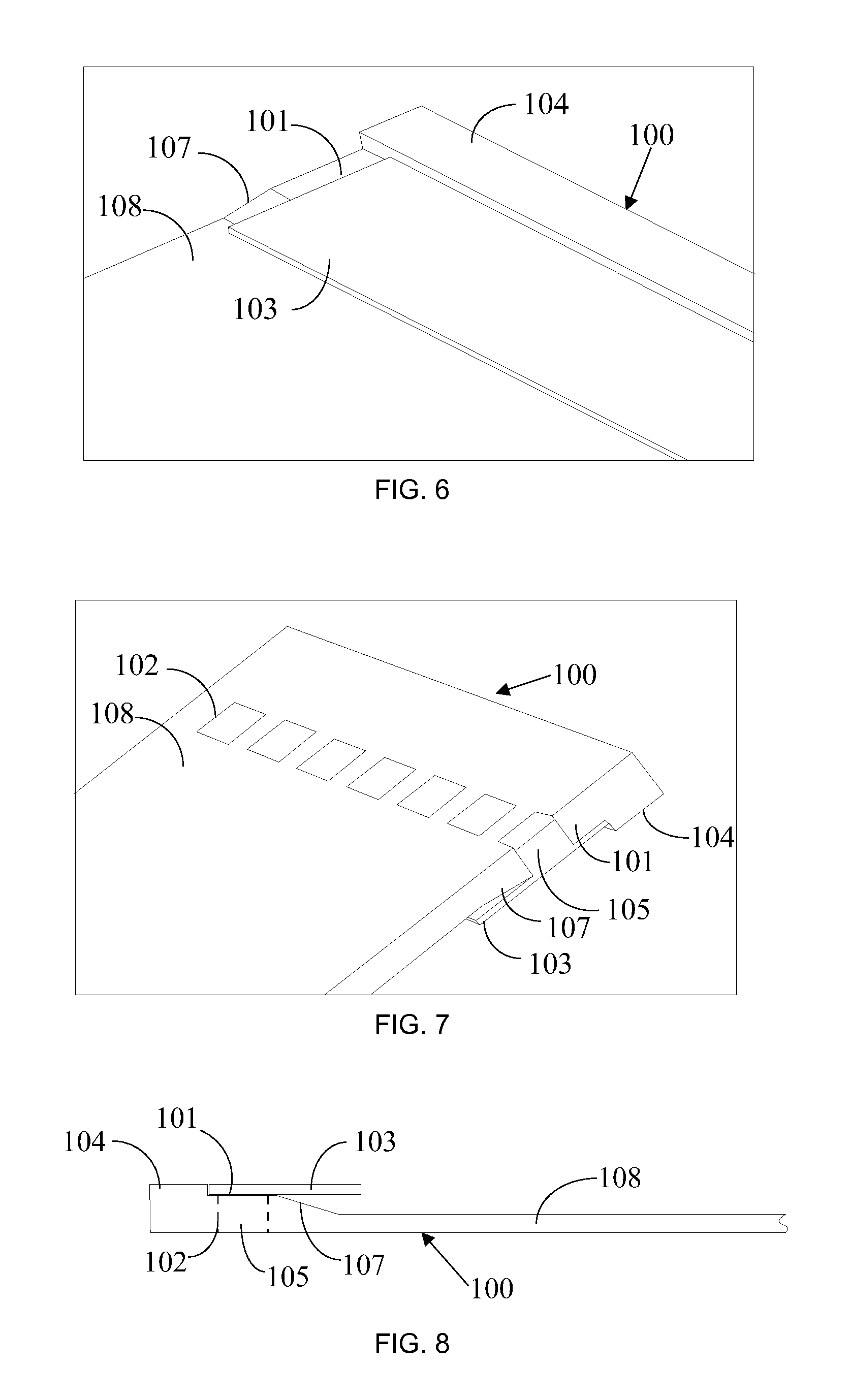
[0045] FIG. 6 is a perspective diagram showing a corner of a backlight module according to an embodiment of the present invention. FIG. 7 is a perspective diagram showing a back side of the back light module of FIG. 6. FIG. 8 is a sectional diagram showing the backlight module of FIG. 6.
[0046] As illustrated, the backlight module contains LEDs 105, a FPC 103, and a light guide plate 100.
[0047] The light guide plate 100 contains a platform 101 of uniform thickness along an edge of the light guide plate 100 for the installation of the FPC 103. The platform 101 is configured with a number of through openings 102 within which the LEDs 105 are installed. The LEDs 105 are welded to pads on the FPC 103. The FPC 103 is adhered to the platform 101. Due to the planar contact between the FPC 103 and the platform 101, the connection between the two is more stable.
[0048] The light guide plate 100 can be of various shapes such as a planar light guide plate 100 or a wedge-shaped light guide plate 100. Alternatively, a slope 107 can be configured between the platform 101 and the main region 108 of the light guide plate 100. The thickness of the main region 108 of the light guide plate 100 is smaller than that of the platform 101. Alternatively, a blocking rim 104 can be configured along the outer sides of the openings 102. The blocking rim 104 is raised above the platform 101 to provide fixation to the FPC 103 from a lateral side so that its installation is even more stable.
[0049] The present invention further provides a display device incorporating the light guide plate and the backlight module described above.
[0050] Embodiments of the present invention have been described, but not intending to impose any unduly constraint to the appended claims. Any modification of equivalent structure or equivalent process made according to the disclosure and drawings of the present invention, or any application thereof, directly or indirectly, to other related fields of technique, is considered encompassed in the scope of protection defined by the clams of the present invention.
* * * * *
D00000
D00001
D00002
D00003
XML
uspto.report is an independent third-party trademark research tool that is not affiliated, endorsed, or sponsored by the United States Patent and Trademark Office (USPTO) or any other governmental organization. The information provided by uspto.report is based on publicly available data at the time of writing and is intended for informational purposes only.
While we strive to provide accurate and up-to-date information, we do not guarantee the accuracy, completeness, reliability, or suitability of the information displayed on this site. The use of this site is at your own risk. Any reliance you place on such information is therefore strictly at your own risk.
All official trademark data, including owner information, should be verified by visiting the official USPTO website at www.uspto.gov. This site is not intended to replace professional legal advice and should not be used as a substitute for consulting with a legal professional who is knowledgeable about trademark law.