Flexible Liquid Desiccant Heat And Mass Transfer Panels With A Hydrophilic Layer
Hamlin; Thomas J. ; et al.
U.S. patent application number 15/117419 was filed with the patent office on 2016-12-29 for flexible liquid desiccant heat and mass transfer panels with a hydrophilic layer. This patent application is currently assigned to 3M INNOVATIVE PROPERTIES COMPANY. The applicant listed for this patent is 3M INNOVATIVE PROPERTIES COMPANY. Invention is credited to Laurence W. Bassett, Rajeev Dhiman, Thomas J. Hamlin.
| Application Number | 20160377302 15/117419 |
| Document ID | / |
| Family ID | 54009560 |
| Filed Date | 2016-12-29 |


| United States Patent Application | 20160377302 |
| Kind Code | A1 |
| Hamlin; Thomas J. ; et al. | December 29, 2016 |
FLEXIBLE LIQUID DESICCANT HEAT AND MASS TRANSFER PANELS WITH A HYDROPHILIC LAYER
Abstract
Provided are flexible panel devices that use desiccants for heat and mass transfer processes, including but not limited to air conditioning systems, for example, liquid desiccant air conditioning (LDAC) applications wherein the liquid desiccant is contained in a panel that comprises at least one hydrophilic separation layer, which allows water vapor transfer between the air and liquid desiccant and enable dehumidification and humidification of the air. The flexible panel devices can be installed on an absorber (conditioner) side or a desorber (regenerator) side or both of a LDAC system. The devices have two flexible layers, at least one of which comprises a flexible and water vapor permeable hydrophilic separation layer, that form a desiccant flow channel and a desiccant flow distributor located therein. The two flexible layers may both be permeable hydropholic separation layers, or they may comprise one permeable hydrophilic separation layer along with another layer that may be a non-porous structure or a water-vapor permeable hydrophobic separation layer.
| Inventors: | Hamlin; Thomas J.; (Vernon, CT) ; Bassett; Laurence W.; (Killingworth, CT) ; Dhiman; Rajeev; (North Haven, CT) | ||||||||||
| Applicant: |
|
||||||||||
|---|---|---|---|---|---|---|---|---|---|---|---|
| Assignee: | 3M INNOVATIVE PROPERTIES
COMPANY St. Paul MN |
||||||||||
| Family ID: | 54009560 | ||||||||||
| Appl. No.: | 15/117419 | ||||||||||
| Filed: | February 25, 2015 | ||||||||||
| PCT Filed: | February 25, 2015 | ||||||||||
| PCT NO: | PCT/US15/17442 | ||||||||||
| 371 Date: | August 8, 2016 |
Related U.S. Patent Documents
| Application Number | Filing Date | Patent Number | ||
|---|---|---|---|---|
| 61946352 | Feb 28, 2014 | |||
| Current U.S. Class: | 165/56 |
| Current CPC Class: | F24F 3/147 20130101; F24F 3/1417 20130101 |
| International Class: | F24F 3/147 20060101 F24F003/147; F24F 3/14 20060101 F24F003/14 |
Claims
1. A heat and mass transfer panel for water vapor exchange with a liquid desiccant, the panel comprising: a desiccant flow channel defined by a first flexible layer and a second flexible layer, at least one of which comprises a flexible hydrophilic water vapor-permeable separation layer; a desiccant inlet and a desiccant outlet to the desiccant flow channel; and a flexible desiccant flow distributor located in the desiccant flow channel.
2. The heat and mass transfer panel of claim 1, wherein both the first and the second flexible layers comprise a flexible hydrophilic water-vapor permeable separation layer.
3. The heat and mass transfer panel of claim 1, wherein the first flexible layer comprises a flexible hydrophilic water-vapor permeable separation layer and the second flexible layer is a non-porous layer or a hydrophobic water-vapor permeable separation layer.
4. The heat and mass transfer panel of claim 1, wherein the flexible hydrophilic water-vapor permeable separation layer or layers independently comprise a membrane, a woven mesh, a nanofiber media, an electrospun fiber media, a glass fiber media, a nonwoven melt blown fiber media, a corrosion-resistant metal, a ceramic media, or combinations thereof.
5. The heat and mass transfer panel of claim 1, wherein the flexible hydrophilic water-vapor permeable separation layer or layers independently comprise a micro-filtration or an ultra-filtration membrane comprising a hydrophilic nylon (PA) membrane, a hydrophilized polyethersulfone (PES) membrane, a hydrophilized polysulfone (PS) membrane, a hydrophilized polyvinylidene fluoride (PVDF) membrane, a hydrophilic polyacrylonitrile (PAN) membrane, a hydrophilized polypropylene (PP) membrane, a hydrophilized polyethylene (PE) membrane, a hydrophilized polytetrafluorethylene (PTFE) membrane, a hydrophilized polycarbonate (PC) membrane, a hydrophilized ethylene chlorotrifluoroethylene (ECTFE) membrane, or combinations thereof.
6. The heat and mass transfer panel of claim 1, wherein the desiccant flow distributor comprises a hydrophilic material that comprises a polymeric material, a natural fiber, or combinations thereof.
7. The heat and mass transfer panel of claim 6, wherein the desiccant flow distributor comprises a hydrophilic polymer material that comprises a membrane, an open cell foam, a porous nonwoven material, a porous woven material, or combinations thereof.
8. The heat and mass transfer panel of claim 1, wherein the desiccant flow distributor comprises one or more draw-and-drip features at an outlet end of the distributor; wherein the draw-and-drip features are effective for facilitating uniform flow through the panel.
9. The heat and mass transfer panel of claim 1 further comprising an air channel layer.
10. The heat and mass transfer panel of claim 1 further comprising a desiccant distribution header.
11. A heat and mass transfer module comprising: one or more panels of claim 1 assembled among one or more air channel layers or air gaps; and an air inlet and an air outlet.
12. The heat and mass transfer module of claim 11 further comprising two end plates between which the one or more panels and the one or more air channel layers are assembled.
13. A method for water vapor exchange between air and a liquid desiccant, the method comprising: contacting the panel of claim 1 with air having a water vapor pressure different from the equilibrium vapor pressure in a desiccant flowing through the desiccant flow channel; wherein the humidity of the air after contact with the panel is different from the humidity before contact with the panel.
14. A desiccant flow distributor comprising: a hydrophilic structure comprising a polymeric material, a natural fiber, or combinations thereof; and one or more draw-and-drip features at an outlet end of the structure; wherein the draw-and-drip features are effective for facilitating uniform flow therethrough.
15. The desiccant flow distributor of claim 14 comprising a hydrophilic polymeric material that comprises a membrane, an open cell foam, a porous nonwoven material, a porous woven material, or combinations thereof.
16. The desiccant flow distributor of claim 14, wherein the one or more draw-and-drip features comprise a series of edges such that the linear edge near or at the outlet end of the structure is longer than the linear edge at the inlet end of the structure.
17. The desiccant flow distributor of claim 14, wherein the one or more draw-and-drip features comprise a series of shapes defined by or at the edges of the outlet end.
Description
TECHNICAL FIELD
[0001] This disclosure relates to flexible panel devices that use desiccants for heat and mass transfer processes, including but not limited to air conditioning systems. Specifically, devices disclosed herein are particularly useful in liquid desiccant air conditioning (LDAC) applications wherein heat and mass transfer is achieved with a panel that comprises one or more hydrophilic separation layers that are wettable by the desiccant. A desiccant flow distributor located in the panel is hydrophilic and is fabricated to provide excellent wicking and drawing of the desiccant through the panel.
BACKGROUND
[0002] The use of liquid desiccants for dehumidification of air has been known for well over 75 years. The application of liquid desiccants in dehumidification applied in heating, ventilating, and air conditioning (HVAC) systems has been worked on for many years. Open absorption systems for air conditioning are desirable due to their relatively simple design and driving energy at relatively low temperatures. Liquid desiccant air conditioning (LDAC) is an exemplary open absorption system.
[0003] Membrane modules have been researched and attempted for use in LDAC systems. Some module designs incorporated three fluid paths: one for desiccant, one for air, and one for coolant; and other designs incorporate two fluid paths: one for desiccant and one for air. Certain designs have provided benefits on the performance of the absorber side of the system but not on the desorber side, and overall commercial success of liquid desiccant air conditioning (LDAC) systems has been extremely limited.
SUMMARY
[0004] Provided are heat and mass transfer panels, heat and mass transfer modules, and methods of making and using the same.
[0005] In a first aspect, a heat and mass transfer panel for water vapor exchange with a liquid desiccant is provided, the panel comprising: a desiccant flow channel defined by a first flexible porous layer and a second flexible layer, at least one of which comprises a flexible hydrophilic separation layer; a desiccant inlet and a desiccant outlet to the desiccant flow channel; and a flexible desiccant flow distributor located in the desiccant flow channel.
[0006] Another aspect provides heat and mass transfer modules comprising: one or more panels disclosed herein assembled among one or more air channel layers or air gaps; and an air inlet and an air outlet.
[0007] Other features that may be used individually or in combination with respect to any aspect of the invention are as follows.
[0008] Both the first and the second flexible layers may comprise a flexible hydrophilic water-vapor permeable separation layer. Or, the first flexible layer may comprise a flexible hydrophilic water-vapor permeable separation layer and the second flexible layer may be a non-porous layer or a hydrophobic water-vapor permeable separation layer. The flexible hydrophilic water-vapor permeable separation layer or layers may independently comprise a membrane, a woven mesh, a nanofiber media, an electrospun fiber media, a glass fiber media, a nonwoven melt blown fiber media, a corrosion-resistant metal, a ceramic media, or combinations thereof. The flexible hydrophilic water-vapor permeable separation layer or layers may independently comprise a micro-filtration or an ultra-filtration membrane comprising a hydrophilic nylon (PA) membrane, a hydrophilized polyethersulfone (PES) membrane, a hydrophilized polysulfone (PS) membrane, a hydrophilized polyvinylidene fluoride (PVDF) membrane, a hydrophilic polyacrylonitrile (PAN) membrane, a hydrophilized polypropylene (PP) membrane, a hydrophilized polyethylene (PE) membrane, a hydrophilized polytetrafluorethylene (PTFE) membrane, a hydrophilized polycarbonate (PC) membrane, a hydrophilized ethylene chlorotrifluoroethylene (ECTFE) membrane, or combinations thereof.
[0009] In some embodiments, the desiccant flow distributor is effective to uniformly spread desiccant under head pressure conditions of 12 inches (30.5 cm) of water or less. The desiccant flow distributor may be effective to uniformly spread desiccant under head pressure conditions in the range of atmospheric pressure to less than or equal to 12 inches (30.5 cm) of water.
[0010] The desiccant flow distributor may comprise a hydrophilic material that comprises a polymeric material, a natural fiber, or combinations thereof. The desiccant flow distributor may comprise a hydrophilic polymer material that comprises a membrane, an open cell foam, a porous nonwoven material, a porous woven material, or combinations thereof. The desiccant flow distributor may comprise a hydrophilic polymer material that comprises a rail film, an extruded web material, an apertured polymeric film, or combinations thereof. The desiccant flow distributor may comprise a hydrophilic natural fiber that comprises cellulose. The desiccant flow distributor may comprise an open cell foam of a hydrophilized polyether urethane or a hydrophilized polyester urethane. The desiccant flow distributor may comprise one or more draw-and-drip features at an outlet end of the distributor; wherein the draw-and-drip features are effective for facilitating uniform flow through the panel.
[0011] The non-porous layer may comprise polyethylene, cast, polypropylene, oriented polypropylene, PET (polyethylene terephthalate), bi-axially oriented PET, bi-axially oriented PET with aluminum or gold vapor deposited on the surface, PA (polyamide), PVC (polyvinylchloride), EVOH (ethylene vinyl alcohol) and/or co-extruded/multilayer film constructions thereof.
[0012] The heat and mass transfer panels may further comprise an air channel layer. The heat and mass transfer panels may further comprise a desiccant distribution header.
[0013] In one or more embodiments, the heat and mass transfer panels, upon contact with air having a water vapor pressure higher than the equilibrium vapor pressure of the desiccant, are effective to transfer water vapor from the air to a desiccant flowing through the desiccant channel. In one or more embodiments, the heat and mass transfer panels, upon contact with air having a water vapor pressure lower than the equilibrium vapor pressure of the desiccant, are effective to transfer water vapor from the desiccant to the air.
[0014] The heat and mass transfer modules may further comprise two end plates between which the one or more panels and the one or more air channel layers are assembled. The end plates may be mechanically fastened together. In some instances, there are fewer desiccant inlets than desiccant outlets. In other instances, there are fewer desiccant outlets than desiccant inlets.
[0015] Further aspects provide methods for water vapor exchange between air and a liquid desiccant, the methods comprising: contacting any panel disclosed herein with air having a water vapor pressure different from the equilibrium vapor pressure in a desiccant flowing through the desiccant flow channel; wherein the humidity of the air after contact with the panel is different from the humidity before contact with the panel.
[0016] When the water vapor pressure of the air is higher than the equilibrium vapor pressure of the desiccant, the method may further comprise transferring the water vapor from the air to the desiccant, and the humidity of the air after contact with the panel is less than the humidity before contact with the panel. When the equilibrium vapor pressure of the desiccant is higher than the water vapor pressure of the air, the method may further comprise transferring the water vapor from the desiccant to the air, and the humidity of the air after contact with the panel is more than the humidity before contact with the panel. The desiccant flow distributor may comprises one or more draw-and-drip features at an outlet end of the distributor; wherein the draw-and-drip features are effective for facilitating uniform flow through the panel.
[0017] Another method is a method of making a heat and mass transfer panel, the method comprising: forming a desiccant flow channel defined by a first flexible layer and a second flexible layer, at least one of which comprises a flexible hydrophilic water vapor-permeable separation layer; locating a flexible desiccant flow distributor in the desiccant flow channel; assembling the first flexible layer, the second flexible layer, and the flexible desiccant flow distributor; and providing or forming a desiccant inlet and a desiccant outlet to the desiccant flow channel.
[0018] A further aspect is a desiccant flow distributor comprising: a hydrophilic structure comprising a polymeric material, a natural fiber, or combinations thereof; and one or more draw-and-drip features at an outlet end of the structure; wherein the draw-and-drip features are effective for facilitating uniform flow therethrough. The desiccant flow distributor may comprise a hydrophilic polymeric material that comprises a membrane, an open cell foam, a porous nonwoven material, a porous woven material, or combinations thereof. The one or more draw-and-drip features may comprise a series of edges such that the linear edge near or at the outlet end of the structure is longer than the linear edge at the inlet end of the structure. The one or more draw-and-drip features may comprise a series of shapes defined by or at the edges of the outlet end.
[0019] These and other aspects of the invention are described in the detailed description below. In no event should the above summary be construed as a limitation on the claimed subject matter.
BRIEF DESCRIPTION OF THE DRAWINGS
[0020] The accompanying drawings are included to provide a further understanding of the invention described herein and are incorporated in and constitute a part of this specification. The drawings illustrate exemplary embodiments. Certain features may be better understood by reference to the following detailed description when considered in connection with the accompanying drawings, in which like reference numerals designate like parts throughout the figures thereof, and wherein:
[0021] FIG. 1 is a schematic illustrating condensation followed by hydraulic breakthrough resulting from prior art structures;
[0022] FIG. 2 is a process flow chart for an exemplary flexible panel fabrication system;
[0023] FIGS. 3A-3B show an exemplary panel in an expanded schematic view (FIG. 3A) and in an assembled schematic view (FIG. 3B);
[0024] FIG. 4 is a schematic view of a combination of an exemplary air channel layer and air channel seals;
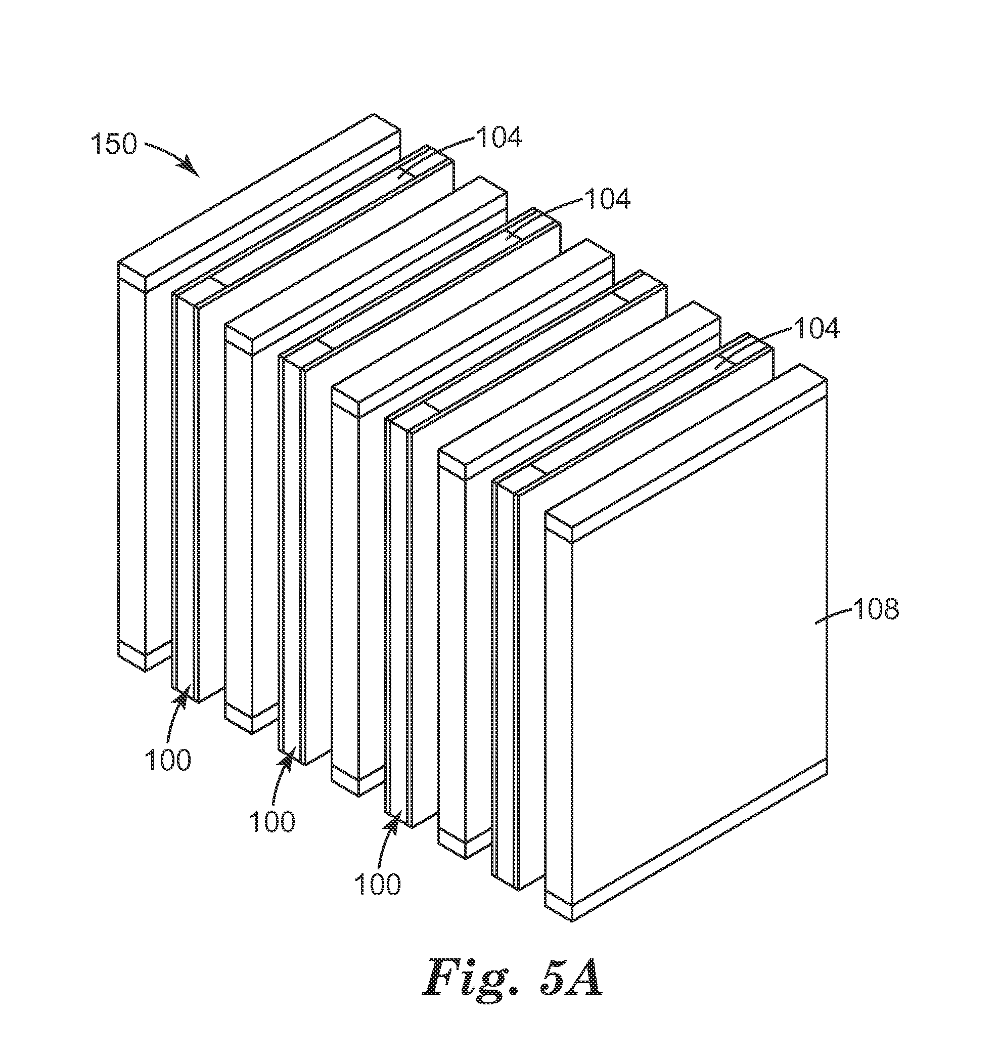
[0025] FIGS. 5A-5B show an exemplary module in an expanded schematic view (FIG. 5A) and in an assembled schematic view (FIG. 5B);
[0026] FIG. 6 is an embodiment of a flexible liquid desiccant heat and mass transfer panel with two air channel layers in a module assembly having two end plates; and
[0027] FIGS. 7A-7D provide schematic depictions of exemplary draw-and-drip features having various shapes.
[0028] The figures are not necessarily to scale. Like numbers used in the figures refer to like components. It will be understood, however, that the use of a number to refer to a component in a given figure is not intended to limit the component in another figure labeled with the same number.
DETAILED DESCRIPTION
[0029] Provided are improved flexible panel devices that use desiccants for heat and mass transfer processes, including but not limited to air conditioning systems, for example, liquid desiccant air conditioning (LDAC) applications allowing heat and water vapor transfer between the air and liquid desiccant, which enable dehumidification and/or humidification of the air. The flexible panel devices may be installed on an absorber (conditioner) side or a desorber (regenerator) side or both of a LDAC system.
[0030] The devices have two flexible layers, at least one of which comprises a flexible and hydrophilic separation layer, that form a desiccant flow channel and a desiccant flow distributor located therein. The two flexible layers may both be hydrophilic separation layers, or they may comprise one hydrophilic separation layer along with another layer that may be a non-porous structure or a water-vapor permeable hydrophobic separation layer. An air channel layer is an optional layer.
[0031] The at least one flexible porous hydrophilic separation layer controls a thin film of liquid desiccant within the pores and on the surfaces of the separation layer via surface tension and capillary action. The separation layer(s) are in contact with a hydrophilic desiccant flow distributor which provides hydrodynamic control of a falling column of liquid desiccant between the separation layers. The use of porous hydrophilic separation layer(s) in flexible liquid desiccant heat and mass transfer panels has significant advantages over the use of porous hydrophobic separation layers.
[0032] The following terms shall have, for the purposes of this application, the respective meanings set forth below.
[0033] A "panel" is a fundamental structure for achieving mass and/or heat transfer. Panels may provide multiple functionalities such as water vapor separation, distribution of a desiccant, and management of condensation. Panels may comprise two layers, at least one hydrophilic layer and another layer, to form a channel through which desiccant flows. The hydrophilic layer facilitates water vapor transfer. The channel may contain a desiccant flow distributor to facilitate substantially uniform flow through the channel.
[0034] A "module" is an assembly of several panels to achieve mass and/or heat transfer in practical commercial quantities.
[0035] "Flexible layers" and "flexible panels" refer to structures that are non-rigid and can be rolled onto itself and unrolled without damage. In one or more embodiments, such layers or panels may be rolled 180 degrees around a radius that is less than or equal to five (or two and one-half, or even less than or equal to one) times the thickness of the layer without damage.
[0036] "Hydrophilic" means that the liquid desiccant is able to invade and wet the pores of the separation layer. This effect can be quantified by Eq. (1) which gives the criterion for a liquid to invade a textured solid depending on its intrinsic wettability with the solid and the details of the textures:
cos .theta. .gtoreq. 1 - .phi. s r - .phi. s ( 1 ) ##EQU00001##
[0037] where .theta. is the contact angle of the liquid with the solid without any textures (i.e. smooth), .phi..sub.s is the solid fraction (between 0 and 1), and r (.gtoreq.1) is the ratio of true surface area of the solid to its projected area. For a porous solid, r is infinity, which implies that .theta..ltoreq.90.degree., i.e. any liquid with contact angle less than 90.degree. will eventually invade a porous material. Eq. (1) merely predicts whether or not a given liquid will invade a porous solid, but it does not predict how quickly this will happen. This feature of a porous material distinguishes it from solids having textures only on their surfaces where the condition for liquid invasion is more restrictive. For example, for .phi..sub.s=0.1 and r=2, .theta..ltoreq.62.degree., implying that only liquids with contact angle less than 62.degree. will be able to invade the solid textures. Thus "hydrophilic" in this context means .theta..ltoreq.90.degree., preferably .theta. should be as small as possible and preferably .theta..ltoreq.75.degree..
[0038] A "hydrophilic separation layer," therefore, refers to a structure that is wettable by the liquid desiccant solutions. Exemplary such structures include but are not limited to: a membrane, a woven mesh, a nanofiber media, an electrospun fiber media, a glass fiber media, a nonwoven melt blown fiber media, a corrosion-resistant metal, a ceramic media, or combinations thereof, which are hydrophilic by virtue of the materials used to fabricate the layer and/or by treatment. Exemplary membranes are micro-filtration or ultra-filtration membranes.
[0039] In addition, "hydrophobic water vapor-permeable separation layer" and "hydrophobic separation layer" refer to a structure that is porous to water vapor but is not wettable by the liquid desiccant solutions.
[0040] A "liquid desiccant" is a hygroscopic material which has the ability to both absorb or desorb water vapor into or from solution based on partial pressure differences. Examples of suitable desiccants are halide salts (such as lithium chloride, calcium chloride, and mixtures thereof, and lithium bromide) and glycols (such as triethylene and propylene glycol).
[0041] A "porous separation layer" is the layer of material in the flexible panel that controls the interface between the liquid desiccant and the air (or any gas) to be dehumidified or humidified. "Control" means to promote both heat and mass transfer between the liquid desiccant and the air while ensuring that liquid desiccant is not released, aerosolized, and entrained in the air stream. Liquid desiccants are typically corrosive salts (i.e. lithium chloride, calcium chloride) and can cause many problems in heating, ventilation, and air conditioning (HVAC) systems if they are allowed into the air stream. Corrosion of equipment components, corrosion of ductwork, and health and safety concerns have prevented the widespread use of liquid desiccants in HVAC systems and improved solutions to liquid desiccant control are needed.
[0042] It has been found that the use of hydrophobic water vapor permeable separation layers to control the liquid desiccant and air interface as described in the prior art have some limitations. When used in LDAC systems in instances where the desiccant enters the heat and mass exchanger at a temperature lower than the dew point, one limitation is that condensation can occur on the air side surface of the separation layers as well as within the pores of the layer. Beads of liquid discharging to the air side will bead on the outer surface of the hydrophobic membrane as the bulk of the outer surface is still hydrophobic and not readily wetted. The formation of beads will cause air flow to be blocked on the air side and beads have a much higher chance of being aerosolized or otherwise carried down the air stream. This phenomenon will continue to spread as condensation continues to form bridges across the layer. The ability of the hydrophobic water vapor permeable separation layer to adequately control the desiccant can only be restored if the layer is completely dried to eliminate all liquid bridging. Even if the hydrophobic separation layer is dried, there may be residual salt left on the internal surfaces of the layer which could promote rewetting.
[0043] In addition, capillary condensation can occur at temperatures above the dew point (below the saturation vapor pressure) within the pores of the layer. The probability of occurrence increases if the pore structure of the separation layer is small as can be found in the pore distribution of micro-filtration membranes, and in ultra-filtration, nano-filtration, and osmotic membranes. Any condensation that fills the pores and bridges the thickness of the layer will create a hydraulic path where desiccant leakage can occur. Turning to FIG. 1, which is a schematic illustrating condensation 14 followed by hydraulic breakthrough 18 resulting from prior art structures, if the pressure on the desiccant side 12 of a hydrophobic separation layer or membrane 10 (P.sub.desiccant) is greater than the pressure on the air side 16 (P.sub.air), hydraulic leaks 18 will occur and desiccant will be discharged to the air stream side. This can be most problematic on modular and desiccant flow circuit designs where the desiccant pressure is .gtoreq.0.5 psig (14 inches or 35.5 cm) or on designs where there is a totally open desiccant channel with no desiccant flow distributor.
[0044] Furthermore, any surface contamination due to materials such as surfactants, greases, or oils can affect the surface energy of the hydrophobic water vapor permeable separation layers further complicating the ability of the layer to effectively retain the desiccant. This can also be most problematic on modular and desiccant flow circuit designs where the desiccant pressure is .gtoreq.0.5 psig (14 inches or 35.5 cm) or on designs where there is a totally open desiccant channel with no desiccant flow distributor.
[0045] A limitation when using a hydrophobic water vapor permeable separation layer is that the air/desiccant interface occurs on the desiccant side of the layer. This means that there is a heat transfer resistance in the heat and mass exchanger due to the stagnant layer of air occurring within the pore structure of the layer. By moving the air/desiccant interface to the outside of the hydrophilic layer(s), high heat transfer of water through the hydrophilic layer(s) is achieved.
[0046] The heat transfer resistance, R.sub.th,sep posed by the hydrophobic separation layer can be determined as: R.sub.th,sep=t/k where t and k are the thickness and thermal conductivity (determined by the porosity-weighted sum of the thermal conductivities of the layer material and air) of the separation layer. For instance, for a polypropylene separation layer of 50 .mu.m thickness and 70% porosity, k.apprxeq.0.7k.sub.air+0.3k.sub.PP=0.0796 W/mK and R.sub.th,sep=6.281.times.10.sup.-4 m.sup.2K/W. By contrast, for a hydrophilic separation layer of the same thickness and similar thermal conductivity, k.apprxeq.0.7k.sub.water+0.3k.sub.PP=0.48 W/mK and R.sub.th,sep=1.042.times.10.sup.-4 m.sup.2K/W, which is over six times smaller than the hydrophobic case and, as a result, will yield higher heat transfer rates for a given surface area and temperature difference.
[0047] The mass transfer resistance R.sub.m,sep posed by the hydrophilic separation layer may be higher or lower than the hydrophobic case depending on whether the liquid desiccant within the layer is stationary or mobile. The mobility of the desiccant is difficult to determine theoretically and can be manipulated by suitable choices of separation layer and desiccant distributor materials. In addition, the magnitude of R.sub.m,sep has to be compared with the other two mass transfer resistances (air-side and desiccant-side) in the system in order to establish whether R.sub.m,sep could be a significant bottleneck for mass transfer. There is an advantage in using a hydrophilic separation layer in that it stays in intimate contact with the desiccant distributor due to surface tension and enhances overall heat and mass transfer through this contact. These considerations make experimental testing necessary in order to determine mass transfer performance of the hydrophilic separation layers.
The Panels
[0048] In this invention, the use of a porous hydrophilic separation layer has eliminated the stagnant air layer present in the hydrophobic water vapor permeable separation layer as described in the prior art. A particularly useful material for use as a desiccant flow distributor is a porous hydrophilic open cell foam. The effective use of the porous hydrophilic separation layer is enabled by the use of a gravity feed desiccant flow system in combination with a porous hydrophilic open cell foam as the desiccant flow distributor. The structure and shape of the foam can be manipulated to optimize the desiccant flow between two porous hydrophilic separation layers or between one hydrophilic separation layer and another layer that may be a non-porous structure or a water-vapor permeable hydrophobic separation layer. When liquid is fed into the top of a panel with this construction, the open cell foam spreads the liquid uniformly between the separation layers as it flows downward due to the effect of gravity. The porous hydrophilic separation layer, unlike a hydrophobic material, wets out with the liquid and all the pores become filled. The stagnant air layer is unable to form within the separation layer. Furthermore, surface tension forces keep the hydrophilic separation layer and desiccant distributor in intimate contact and prevent any air entrapment in between. It is important that the open cell foam desiccant distributor be hydrophilic upon initial wetting with the desiccant. Once it has been wetted, it should remain wet as long as the vapor pressure gradient of the environment in which the panel resides favors water absorption. After initial wetting, even if the desiccant loaded panels are dried with high temperature dry air, the panels should re-wet without problem due to the salt left behind from the evaporation of the water from the drying operation. In other words, the porous hydrophilic separation layer should be hydrophilic enough to initially thoroughly wet and fill out all the pores under the gravity flow condition.
[0049] The effect of the fluid flowing through the open cell foam desiccant distributor to a discharge at the base of the panel is to create a controlled desiccant flow with minimal positive pressure. By positive pressure, it is meant that the liquid pressure between the separation layers is only slightly above atmospheric pressure and does not exceed the height of the liquid column provided in the desiccant distribution header. The combination of the minimal positive pressure gradient with a hydrophilic porous separation layer which has a fairly high flow resistance is to create a panel where the desiccant flow is sequestered within the pores of the separation layer in an extremely thin, highly spread liquid layer on the air side of the separation layer. This can be referred to as a stable film in that under the airflows per unit of active heat and mass exchanger surface area anticipated in a LDAC, it is virtually impossible to aerosolize and entrain desiccant in the airstream. In addition, the wetted separation layers stay in intimate contact with the desiccant distributor due to surface tension of the liquid. This eliminates any air gaps and maximizes heat and mass transfer efficiency.
[0050] Also, when flow into the top of the panel is stopped, for example, when used in an LDAC and the unit is turned off, the desiccant can be stabilized within the pore structure of the hydrophilic separation layer due to capillary forces alone. In some embodiments, desiccant may drain out, but will uniformly distribute again upon introduction of desiccant flow. In any case, the desiccant is prevented from forming drips or leaks which could enter the air stream and be entrained into the air in the form of an aerosol.
[0051] The arrangement of a porous hydrophilic separation layer such as a membrane in contact with a hydrophilic porous material such as open-cell foam effectively solves the widespread problem of carryover encountered in liquid desiccant systems. This solution originates primarily from the fact that the liquid is held tightly on the surface via surface tension, and within the pores of the separation layer by virtue of capillary forces, which are far greater than the shear imposed by the passing air stream. This can be shown as follows.
[0052] Ishii and Grolmes (M. Ishii & M. Grolmes (1975), Inception criteria for droplet entrainment in two phase concurrent film flow, AICHE Journal, Vol 21 2 308-318) showed that a gas stream passing over a liquid stream can dislodge droplets from the liquid if the shear imposed by the gas overcomes the surface tension forces, resulting into the following criterion for droplet entrainment:
.mu. f v g .gamma. .rho. g .rho. f .gtoreq. 11.78 N .mu. 0.8 Re f - 1 / 3 for N .mu. .ltoreq. 1 15 ( 2 ) ##EQU00002##
[0053] where .mu..sub.f, .rho..sub.f, and .gamma. are the viscosity, density, and surface tension of the liquid, respectively, and .rho..sub.g and .nu..sub.g are the density and velocity of the gas stream.
N .mu. = .mu. f [ .rho. f .gamma. .gamma. g .DELTA..rho. ] 1 / 2 ##EQU00003##
is referred as viscosity number and the liquid Reynolds number
Re f = 4 .rho. f v f .delta. .mu. f , ##EQU00004##
where .DELTA..rho. is the density difference between the liquid and gas, and .delta. is the liquid film thickness. For air-aqueous LiCl system, N.sub..mu.=0.0097 which is <1/15, indicating that the criterion of Eq. (2) is applicable. If the liquid completely wets (i.e. contact angle, .theta.=0 deg.) the separation layer, de Gennes et al. (P. G. de Gennes, F. Brochard-Wyart, & D. Quere, Capillary and Wetting Phenomena, Springer Publishing 2004) have shown that its thickness is governed by the balance of surface tension and van der Waals forces and is typically on the order of 1 nm. If .theta.>0 deg., microscopic features of the separation layer will remain emerged (i.e. dry) depending on where the local contact angle equals the equilibrium value. We can consider the case of .theta.=0 deg. with .delta.=1 nm. A conservative estimate of .nu..sub.f would be setting it equal to the bulk fluid velocity in the porous material (such as open-cell foam), which would be given by Darcy's law to be about 0.0075 m/s under typical conditions described previously. This gives Re.sub.f=7.2.times.10.sup.-6. .nu..sub.g can be estimated by the typical air CFMs encountered in liquid desiccant systems, giving .nu..sub.g=0.8 m/s. Substituting all these values in the criterion of Eq. (2), the left hand side turns out to be 1.327.times.10.sup.-3, whereas the right hand side is about 14.5, which is five orders of magnitude greater than the left hand side value. This suggests that desiccant droplet entrainment (i.e. carryover) is highly unlikely under the typical air flow conditions encountered in liquid desiccant systems. In fact, even if .delta.=1 mm (for instance, for a few seconds due to condensation of water vapor on separation layer surface), the left hand side was calculated to be two orders of magnitude smaller than the right hand side, indicating that droplet entrainment is highly unlikely.
[0054] Flow resistance of the open cell foam desiccant distributor is also an important consideration in the design of the panel. Flow through such a media is governed by Darcy's law. See A. E. Scheidegger, The physics of flows through porous media, Third ed., University of Toronto Press, Toronto (1974) and K. Boomsma, D. Poulikakos, The effects of compression and pore size variations on the liquid flow characteristics in metal foams, J. Fluids Eng. (2002) 124, pp. 263-272. Darcy's law states that the pressure drop, .DELTA.P across the media is proportional to media length L, fluid viscosity .mu., and fluid velocity .nu., and inversely proportional to media permeability, K:
.DELTA. P L = .mu. K v ( 3 ) ##EQU00005##
[0055] Darcy's law is applicable for slow moving flows characterized by Reynolds number Re=.rho. {square root over (K)}.nu./.mu.<O(1), where .rho. is the fluid density. Experiments were carried out with hydrophilic open-cell foams available from UFP Technologies (Type HS) to study water flow behavior. The key parameter varied was media length, L (95 mm and 160 mm); .DELTA.P was kept constant at 500 Pa (i.e. 2'' of water column). Foam width w and thickness t were 32 mm and 6.35 mm, respectively. Tests were conducted with water at room temperature and the resulting flow rate .OMEGA. was measured from which .nu.=.OMEGA./(wt) was calculated. Foam permeability K was calculated to be 3.2.times.10.sup.-9 m.sup.2 from Eq. (3) using one of the flow rate measurements. The calculated value was validated by the good agreement found between predicted and measured flow rates at other media lengths. To confirm the applicability of Darcy's law, Re was calculated and found to be 0.6.
[0056] Equation (3) and the Reynold's number can be utilized to determine the bulk flow capacity of a specific panel design and used for optimization of the heat and mass exchanger.
[0057] Assembly of Panels
[0058] It is important that the separation layers be attached or affixed to the desiccant distributor in some manner to make an integral panel. Side seams may be used or created using tapes, adhesives, ultrasonic welding, thermal welding or any other method of attachment. The seams do not have to be liquid tight seals as the low pressure of operation and the capillary action of the materials will control the desiccant within and on the panel. An exemplary tape is a closed cell foam acrylic tape, for example, one of 3M VHB.TM. tapes identified as #4955 and 4959F would be useful.
[0059] Side seams may be eliminated altogether and the panel will still function provided that head pressure is very low, in the range of <1'' (2.5 cm) of water column. An example construction would be to attach or affix the separation layers to the desiccant distributor by using a light adhesive coating between the layers and laminating the assembly together. Additional methods of laminating the separation layers to the desiccant distributor include but are not limited to heat lamination, open flame lamination, ultrasonic point bonding, and adhesive point bonding.
[0060] Should ultrasonic welding be used, some typical parameters include:
[0061] Branson Ultrasonic Welder using a welding horn having an approximate size of 10 inches (25.4 cm) by 0.25 inches (6.3 mm) with the following settings.
[0062] Weld Pressure: 40-60 psi
[0063] Weld Time--0.5 sec to 1.5 sec
[0064] Weld Hold Time--0.5 sec
[0065] Trigger Force--set at 12
[0066] Down speed--set at 30
[0067] Amplitude--set at 100%.
[0068] For commercial purposes, it is desirable to arrange the layers in an efficient and orderly manner. One exemplary process for making a flexible LDAC separation panel is as follows: obtain the materials for the various layers in rolled or bulk form; unwind and/or feed the layers in a stacked form, attach or affix the layers together; cut the layers to length; and affix at least a desiccant inlet and optionally a desiccant outlet. FIG. 2 provides process flow chart for an exemplary flexible panel fabrication system prior to attachment of fluid connections which incorporates an open cell foam slab feeder. In FIG. 2, it is shown that two porous hydrophilic separation layers 101, 103 are unwound 105 and a hydrophilic open cell foam 107 is provided by a slab feeder 109 between the two separation layers. Feed rollers 111 and guide rolls 113 form a structure for receipt by a seamer 115 that provides side seams by any preferred method such as rotary ultrasonic welding, thermal welding, tape or adhesive application. A cutter 117 cuts the seamed structures to size to form heat and mass transfer panels, and the panels are piled in a stack 119.
[0069] FIG. 3A shows an expanded schematic view and FIG. 3B shows an assembled schematic view of an exemplary panel 100 comprising two flexible hydrophilic separation layers 102, a desiccant flow distributor 104, and adhesive tape 106.
[0070] The materials, in particular the open cell foams, used in this invention are also resilient and a small amount of pressure on the ends of stacked panels can be applied to insure conformance of panels relative to each other. The use of open cell foams, for example, allows for a highly resilient panel and assembled module design which can tolerate both the hydraulic and thermal expansion required in the application. It is expected that assembled modules incorporating the flexible panels will need to withstand conditions below freezing as well as temperatures up to 140.degree. F. in operation. This type of flexible construction allows materials to move relative to each other as the panel or module experiences changes in temperature and pressure. This minimizes stress concentrations throughout the assembly and prevents damage to the structure. The panels are highly durable and can be folded, dropped, compressed, and impacted without affecting functionality.
[0071] It would also be useful in the design of a panel to make any seam used on the leading (and/or trailing) edge of the panel conform to a rounded shape to minimize any turbulence and drag in the air channel. This will minimize parasitic losses.
Assembly of Modules
[0072] In general terms, assembly of a module involves placing one or a plurality of panels and optionally air flow layers/plates in a standalone unit. The panel or plurality of panels may be contained within a frame, such as two plates, that allows for desiccant inflow and outflow through the desiccant channel as well as air flow along the outer surface of the panels as facilitated by an air flow layer or plate, which may be affixed to the panel or which may be provided by assembling panels such that there are air gaps between them. FIG. 4 provides a schematic view of a combination of an exemplary air channel layer 108 comprising a hydrophobic open cell foam for directing air and air channel seals 110 that may comprise a hydrophobic closed cell foam. FIG. 5A shows an expanded schematic view and FIG. 5B shows an assembled schematic view of a exemplary module 150 comprising flexible panels 100 and air channel layers 108. In FIGS. 5A-5B, there are four flexible liquid desiccant heat and mass transfer panels that are separated by air channel layers. Desiccant flow is shown through the desiccant flow distributors 104 at one end, and air flow is shown perpendicular to the desiccant flow. FIG. 6 shows an exemplary heat and mass transfer module 150 comprising two end/support plates 152, plate connecting and gap adjustment features 154, one flexible LDAC panel 100 and two air flow channel layers (not numbered). A header 156 may be formed from two layers of film that are hot-melt sealed to both sides of the panel 110 and hot-melt sealed together to form side seals. A tube may be placed in the header to deliver fluid.
[0073] It is noted, in addition, that air and desiccant paths can also be configured in an in-line manner with the air and liquid desiccant in concurrent or countercurrent flow. Automated or semi-automated processes can be used to make the panels and assembled modules in a very cost effective manner. The number of components in the panel and module assembly has been minimized by the embodiments herein.
[0074] It is expected that the flexible panels will be relatively insensitive to the build-up of any dirt and debris on the surface of the porous hydrophilic separation layer. Air filters such as 3M Filtrete 2'' Mini-pleat MERV 14 Commercial Air Filters will generally be used to protect the panels. Any dirt and debris that impinges and collects on the surface of the separation layer will wet out and may slowly increase the effective thickness of the controlled thin film desiccant layer. However, diffusion of water molecules will still continue and it is expected that only a small degradation in performance will occur over time. It was demonstrated in the laboratory that panels could be rinsed clean of any dirt and debris if necessary.
[0075] The desiccant is biocidal and having the desiccant film located within and on the surfaces of the hydrophilic membrane and at the air interface minimizes any chance of bio-fouling or bio-film build-up on the panel or in the module assembly.
[0076] The individual panels can be easily disassembled from the module and compressed to "wring-out" desiccant for recovery and reuse. Panels can be compacted in waste drums for transport and disposal. Panels and modules can be incinerated.
Materials
[0077] Porous Hydrophilic Separation Layers
[0078] Hydrophilic separation layers may comprise a membrane, a woven mesh, a nanofiber media, an electrospun fiber media, a glass fiber media, a nonwoven melt blown fiber media, a corrosion-resistant metal, a ceramic media, or combinations thereof.
[0079] Many types of porous hydrophilic separation materials may be considered for use. Examples include blown melt fiber (BMF) materials made from nylon or other polymers that have been pre or post treated to make the fiber surfaces hydrophilic. Extremely tightly woven mesh materials, nanospun and electrospun fiber media, and glass fiber media can also be considered. Sintered metal could be considered although corrosion resistance will need to be managed by material selection or by use of coatings due to the nature of the desiccant. Porous ceramic materials are also candidates for the separation layer. Hydrophilic micro-filtration and ultra-filtration membranes are very good candidates. Materials particularly well suited for the application can be selected from the group of hydrophilic micro-filtration membranes. This group includes but is not limited to hydrophilic nylon (PA) membranes, hydrophilized polyethersulfone (PES) membranes, hydrophilized polysulfone (PS) membranes, hydrophilized polyvinylidene fluoride (PVDF) membranes, hydrophilic polyacrylonitrile (PAN) membranes hydrophilized polypropylene (PP) membranes, hydrophilized polyethylene (PE) membranes, hydrophilized polytetrafluorethylene (PTFE) membranes, hydrophilized polycarbonate (PC) membranes, and hydrophilized ethylene chlorotrifluoroethylene (ECTFE) membranes. Membranes can be naturally hydrophilic, as is the case with PA membranes, or can be surface modified to render them hydrophilic. Many techniques for hydrophilization can be used including use of co-polymers and other additives in the polymer blend, coating with surfactants or other hydrophilic materials, or grafting of hydrophilic groups to the membrane surfaces using free radical polymerization techniques or radiation grafting.
[0080] It is important for the hydrophilic separation layer to have a high flow resistance as compared to the flow resistance of the desiccant distributor. This creates preferential bulk flow down the desiccant distributor located between the separation layers. It is preferable to use porous hydrophilic separation layers which have pore sizes of 10 micron or less and with a flow resistance which minimizes the exterior film coating which forms on the air channel side due to the very slight hydraulic pressure generated by the fluid column at the top of the panel. It is more preferable to use porous hydrophilic separation layers which have pore sizes of 5 micron or less. Pore sizes can be measured for most materials using a capillary flow porometer. An example porometer is produced by Porous Materials, Incorporated of Ithaca, N.Y.
[0081] A particularly useful porous hydrophilic separation layer is a micro-filtration membrane made from nylon 6,6 as described in U.S. Pat. No. 6,513,666 entitled "Reinforced, Three Zone Microporous Membrane," which is herein incorporated by reference. This type of membrane has multiple zones of different pore size and incorporates a scrim to provide mechanical stability. In the particular embodiments prototyped to date, a membrane designated as BLA080 was used. This membrane has a 1.2 micron zone on one side of the scrim, a 1.2 micron zone within the scrim, and a 0.8 micron zone on the other side of the scrim. When fabricated into the module, the orientation of the membrane was controlled so that the 0.8 micron zone is facing the air stream. The smaller pores have the highest capillary forces so it is advantageous to have this zone controlling the thin film of desiccant at the desiccant air interface. The more open 1.2 micron zone facing the desiccant is better for insuring high mass diffusion of water into the bulk flow of the desiccant occurring in the desiccant distributor. Pore sizes and thicknesses of the zones of the membrane may be tailored for individual applications to achieve desired mass and heat transfer across the thin liquid film in the membrane.
[0082] An exemplary membrane design would be to make a two zone membrane comprising a very open pore structure, say 3.0 micron, in the scrim fill zone, which is approximately 2.5 mils thick, and a tighter pore size adjacent zone, say 0.8 micron, which is 1 mil thick or less. The open pore zone would be positioned facing the desiccant side in a panel and the tight pore zone would face the air stream. This design will minimize mass transfer resistance in the panel. A discussion of how to make an engineered micro-filtration membrane of this type is discussed in patent application WO 2013/154755 entitled "Thin Film Composite Membrane Structures," hereby incorporated by reference.
[0083] In addition, unreinforced (no scrim) hydrophilic membranes would be useful as well. An example of this type of membrane can be found in U.S. Pat. No. 6,706,184 entitled "Unsupported Multizone Microporous Membrane," which is incorporated herein by reference. In particular, polyethersulfone membranes produced with a thin tight pore size on the air channel side and a more open zone facing the desiccant distributor side would work well in the application.
[0084] Desiccant Flow Distributors
[0085] A desiccant flow distributor may include, but is not limited to a hydrophilic material that comprises a polymeric material, a natural fiber, or combinations thereof. In some embodiments, the desiccant flow distributor may comprise a hydrophilic polymer material that comprises a membrane, an open cell foam, a porous nonwoven material, and/or a porous woven material. Some embodiments may use a hydrophilic polymer material that comprises a rail film, an extruded web material, an apertured polymeric film, or combinations thereof as the desiccant flow distributor. The desiccant flow distributor may also comprise a hydrophilic natural fiber that comprises cellulose.
[0086] Open cell foams are typically made from polyurethanes. Both polyether and polyester urethane foams are common. They can be hydrophilized by adding surfactants to the formulation or post treated to make them hydrophilic. The properties of the foam that are typically characterized are density, compression deflection, compression set, pore size expressed in pores per linear inch of material, tensile strength, tear strength, air flow, and wet-out. Examples of useful hydrophilic open cell foams include Type HS or HydroZorb, from UFP Technologies, Georgetown, Mass.
[0087] Desiccant distributors can be rendered hydrophilic by various methods known in the art. For example: U.S. Pat. No. 6,548,727 (Foam/Film composite medical articles, 2003); U.S. Pat. No. 5,254,301 (Process for preparing a sheet of polymer-based foam, 1993); U.S. Pat. No. 4,957,810 (Synthetic sponge-type articles having excellent water retention, 1990); and U.S. Pat. No. 3,781,231 (Physically reinforced hydrophilic foam and method of preparing same, 1973).
[0088] The shape of the hydrophilic open cell foam is also important in controlling the uniform flow and distribution of the desiccant within the panel. An aspect of this invention is to add a series of features, for example, draw-and-drip features, at the bottom of the foam in the panel. These features cause the desiccant to "draw" or "drip" uniformly at the bottom of the panel and promote uniform flow throughout the panel. Uniform flow is important in insuring efficiency of heat and mass transfer in the panel. It is advantageous for the desiccant to uniformly absorb heat and mass as it flows behind the porous hydrophilic separation layer. Any type of channeling of the desiccant would cause uneven heat and mass absorption and reduced heat and mass exchanger efficiency. The features can be a series of crowns, points, or any other shape that promotes drawing or dripping of the desiccant at several points at the bottom of the panel. If the panel is left straight across at the bottom, the effects of surface tension of the fluid interacting with the bottom edge of the desiccant distributor may cause one discharge stream to form, which may inhibit uniform desiccant flow. Example shapes are provided in FIGS. 7A-7D. FIG. 7A shows an exemplary desiccant flow distributor 204 having rectangular shapes 205 at intervals to form draw-and-drip features extending from an end. FIG. 7B shows an exemplary desiccant flow distributor 304 having square shapes 305 at intervals to form draw-and-drip features extending from an end. FIG. 7C shows an exemplary desiccant flow distributor 404 having triangular shapes 405 at intervals to form draw-and-drip features extending from an end. FIG. 7D shows an exemplary desiccant flow distributor 504 having semi-circular shapes 505 at intervals to form draw-and-drip features extending from an end. Other materials can be considered for use as the desiccant distributor but these materials must be able to both wick and flow for them to properly function. Porous wicking materials that can also carry bulk flow include but are not limited to cellulosic sponges, natural sponges, fabrics, and gauzes.
[0089] Air Channel or Turbulation Layers
[0090] It is advantageous to utilize a very open cell foam for the air channel between adjacent panels. A specifically useful type of very open cell foam is a reticulated open cell foam, which has a substantially uniform pore size and a lattice that is wide open. These types of foams are useful for providing a low pressure drop channel with controlled spacing. In addition, the shape of the foam adds some tortuosity and promotes mixing of the air. The mixing of the air helps break up the boundary layer of the air with the desiccant thin film controlled in the porous hydrophilic separation layer. This promotes better heat and mass transfer between the air and the desiccant. It is also advantageous to use a hydrophobic material of construction in the air channel foam. This is helpful as it insures that any desiccant, condensation, or any other source of liquid (water) that gets into the air channel preferentially wets the porous hydrophilic separation layer and due to the thin film controlled desiccant layer in and on the separation layer, is quickly spread and absorbed into the desiccant flow stream. Essentially the water has a zero contact angle with the desiccant and it is impossible for a drop to form on the separation layer surface. In addition, the thickness, pore size, and tortuosity of the air channel layer can be optimized to balance air flow pressure drop with heat and mass transfer performance. Excessive pressure drops in the air channel can lead to parasitic losses due to the fan energy consumed in a LDAC system. The panel space can be determined with analytical and computational modeling to optimize the panel spacing which is related to the power density of an assembled module.
[0091] An example of an effective material for use as air channel spacers is polyester filter foam S-10 from New England Foam Products, LLC, Hartford, Conn.
[0092] It is not required to have a porous air channel spacer in an assembled module. The panels can instead be affixed at set intervals or nonporous spacers can be used at each end of the panel to control the width of the air gaps between panels. In this manner, air gaps will be provided in an assembled module.
[0093] An exemplary air channel layer may comprise a polypropylene rail film with adhesive (structured film) as disclosed in U.S. Pat. No. 6,986,428 to common assignee 3M Innovative Properties Company and hereby incorporated by reference. This film may be useful to make an air side separator and can be designed to provide air channels with low pressure drop and also face support for the flexible LDAC membrane panel when assembled into a module. This film can also be made without the adhesive. In other words, the full geometry of the film can be made of one material such as polypropylene or polyethylene. It is also possible to make the air channel layers out of many other plastics or metals in the form of plates. The air channel layers or plates can be flexible or rigid. The plates can be machined, thermoformed, extruded, cast, or produced in a number of other ways. Rail type films may be modified with surface features to produce mixing of any fluid (i.e. air, liquid desiccant) which flows down the channels of the film. An exemplary layer may comprise a polymer film comprising micromixing surface features such as those disclosed in commonly-assigned U.S. Ser. No. 61/736,729 filed Dec. 13, 2012, entitled "Constructions for Fluid Membrane Separation Devices" and incorporated herein by reference.
[0094] Other materials such as nettings and apertured films can also be considered for use as air channel spacers.
[0095] Desiccant Distribution Header
[0096] The header should promote uniform flow at the top of the panel and it is advantageous to feed the desiccant through a slot or a series of holes. This will insure even distribution at the top of the panel. This works in coordination with the drawing and dripping features at the bottom of the panel to insure uniform desiccant flow behind the porous hydrophilic separation layer. An exemplary header may be made from nonporous polymer film. For example, two layers of film may be hot-melt sealed to both sides of a panel and hot-melt sealed to form side seals. A tube may be placed in the header to deliver fluid.
[0097] Before describing several exemplary embodiments of the invention, it is to be understood that the invention is not limited to the details of construction or process steps set forth in the following description. The invention is capable of other embodiments and of being practiced or being carried out in various ways.
EXAMPLES
Example 1
[0098] A double-sided porous, flexible heat and mass transfer panel in combination with an air channel layer is made by assembling:
[0099] an air channel layer of a reticulated polyester urethane foam at 10 pores per inch (PPI), a density of 1.9 lbs/cu ft, 25% CFD is 0.45 psi, 16 psi tensile strength, elongation 170%, tear strength 4.5 lbs/in, compression set at 50% deflection is 15, volumetric flow rate is 23, 0.25'' thick--product S-10 from New England Foam;
[0100] two porous separation layers of an engineered membrane comprising: a hydrophilic nylon 6,6 membrane, a multi-zone structure with a 1.2 micron zone on the desiccant side and a 0.80 micron zone on the air side, membrane is reinforced with a nonwoven scrim in a center zone--from 3M Purification, U.S. Pat. No. 6,513,666;
[0101] a desiccant flow distributor of a polyether urethane foam, double cell, hydrophilized with a surfactant, 0.25'' thick--Type HS from UFP Technologies, having draw-and-drip features in a series of shapes of triangular point geometry at the bottom of the panel;
[0102] tape side seams comprising multiple layers of a closed cell acrylic foam backed adhesive tape; and
[0103] a desiccant distribution header comprising a multi-layer nonporous polymer film, using a general purpose hot melt to adhere to the membrane and to form side seals of the header.
Example 2
[0104] A single-sided porous, flexible heat and mass transfer panel in combination with an air channel layer was made by assembling:
[0105] an air channel layer of a reticulated polyester urethane foam at 10 pores per inch (PPI), a density of 1.9 lbs/cu ft, 25% CFD is 0.45 psi, 16 psi tensile strength, elongation 170%, tear strength 4.5 lbs/in, compression set at 50% deflection is 15, volumetric flow rate is 23, 0.25'' thick--product S-10 from New England Foam;
[0106] one porous separation layer of an engineered membrane comprising: a hydrophilic nylon 6,6 membrane, a multi-zone structure with a 1.2 micron zone on the desiccant side and a 0.80 micron zone on the air side, membrane is reinforced with a nonwoven scrim in a center zone--from 3M Purification, U.S. Pat. No. 6,513,666;
[0107] one non-porous separation layer comprising a polyethylene film;
[0108] a desiccant flow distributor of a polyether urethane foam, double cell, hydrophilized with a surfactant, 0.25'' thick--Type HS from UFP Technologies, having draw-and-drip features in a series of shapes of triangular point geometry at the bottom of the panel;
[0109] tape side seams comprising multiple layers of a closed cell acrylic foam backed adhesive tape; and
[0110] a desiccant distribution header comprising a multi-layer nonporous polymer film, using a general purpose hot melt used to adhere to the membrane and to form the side seals of the header.
Example 3
[0111] A double-sided porous, flexible heat and mass transfer panel was made by assembling:
[0112] two porous separation layers of an engineered membrane comprising a hydrophilic nylon 6,6 membrane, a multi-zone structure with a 1.2 micron zone on the desiccant side and a 0.80 micron zone on the air side, membrane is reinforced with a nonwoven scrim in a center zone--from 3M Purification, U.S. Pat. No. 6,513,666;
[0113] a desiccant flow distributor of a polyester urethane foam, hydrophilized with a surfactant, 0.25'' thick--type HydroZorb from UFP Technologies, having draw-and-drip features in a series of shapes of triangular point geometry at the bottom of the panel;
[0114] ultrasonically-welded side seams using a Branson Ultrasonic Welder with the following settings:
[0115] Weld Pressure--50 psi
[0116] Weld Time--0.80 sec
[0117] Weld Hold Time--0.5 sec
[0118] Trigger Force--set at 12
[0119] Down speed--set at 30
[0120] Amplitude--set at 100%; and
[0121] desiccant distribution header where an extra membrane was allowed for above the top of the ultrasonically welded side seals enabling the formation of a pocket that served as a desiccant header. A tube or multiple tubes may be inserted into this pocket and desiccant may be pumped directly into the panel.
Example 4
Testing
[0122] Flow Test 1
[0123] A panel as described in Example 2 and with an active membrane area of 6'' wide.times.7'' high.times.one side was tested with water to determine the flow capability of the panel. Active membrane area is defined as the wetted membrane surfaces which have fluid flowing behind it on the desiccant distributor side and does not include any side seams, header area, or the draw-and-drip features at the bottom of the panel. A peristaltic pump was used to deliver the water to the top of the panel and the tube was situated to allow the liquid to drop into the header at the center of the panel. The maximum flow rate of the pump was 88.5 ml/min and the panel could handle this flow rate without issue. Liquid did not build up in the header but rather was drawn into the panel and spread by the hydrophilic open cell foam desiccant distributor. The triangular features started to drip as the liquid began reaching the bottom of the panel. Within two minutes of starting the flow, the dripping was uniformly distributed across the triangular points indicating uniform flow.
[0124] Flow Test 2
[0125] A panel as described in Example 3 and with an active membrane area of 6'' wide.times.7'' high.times.two sides was tested with water to determine the flow capability of the panel. A peristaltic pump was used to deliver the water to the top of the panel and the tube was situated to allow the liquid to drop into the header at the center of the panel. The maximum flow rate of the pump was 88.5 ml/min and the panel could handle this flow rate without issue. Liquid did not build up in the header but rather was drawn into the panel and spread by the hydrophilic open cell foam desiccant distributor. The triangular draw-and-drip features started to drip as the liquid began reaching the bottom of the panel. Within two minutes of starting the flow, the dripping was uniformly distributed across the triangular points indicating uniform flow.
[0126] Flow Uniformity Test
[0127] The flexible panel tested in Flow Test 1 was tested with a solution of methylene blue dye in water to observe the flow distribution within the panel. The panel was mounted without an air channel spacer on one side and with the nonporous film against the plexiglass end plate on the module holder so the flow patterns could be observed. A sequence of photos was taken in increments over the first two minutes of liquid flow and uniform spreading was observed. This was done with a single point feed at the top of the panel. It is thought that a header with multiple feed points or use of a slot feeder would improve the uniformity at the top corners of the panel to insure uniform flow through the entire face of the active membrane area.
[0128] Freeze/Thaw Test
[0129] The panel described in Example 2 and flow tested in Flow Test 1 and in the Flow Uniformity Test was subject to two cycles of freeze/thaw testing. In the first cycle, the panel was completely saturated with water and frozen solid to 10.degree. F. in a freezer compartment over a period of approximately 5 hours. It was frozen as a panel and not restrained in a holder. It was then removed from the freezer and while still frozen, rapidly immersed in a pan of hot water at approximately 125.degree. F. After stabilizing at the bath temperature, the panel was removed and visually examined for damage. No damage was observed. The panel then was remounted into a holder with a foam air channel spacer on the membrane side and the non-porous film side facing the plexiglass end plate on the holder. The panel was tested as described in Flow Test 1 and performed normally.
[0130] This same panel was then mounted in a holder with air channel spacers on each side. It was fully saturated with water and then put back in the freezer. It was frozen solid overnight to 10.degree. F. (approximately 16 hours), removed and then rapidly immersed into 125.degree. F. water as before. Again, no visual damage was observed when visually inspected and the panel was retested for flow performance. It tested normally.
[0131] This experiment indicates that the flexible panel design as described in this invention can withstand a high level of thermal and mechanical stress without damage or reduction in functional performance.
[0132] Condensation Control and Desiccant Retention
[0133] The panel as described in Example 2 was assembled into a holder. Water was introduced into the header as described in Flow Test 1. A pipette was then used to introduce water droplets as a surrogate to condensation formation on the membrane surface. This simulated the case when cold desiccant is introduced into the top of the panel while warm humid air is delivered down the air channel. When the surface temperature of the thin film desiccant controlled in the porous hydrophilic separation layer is below the dew point of the passing air, condensation will form at the interface. The surrogate water droplets demonstrated that when they touched the active membrane surface, they were immediately spread across the face of the panel. Droplets were unable to form on the surface. This demonstrates that any condensation formation at the liquid/air interface will be immediately spread and absorbed into the thin film layer controlled in and on the panel. In this design, there is also no chance for capillary condensation as the separation layer operates in a totally wetted form.
[0134] In addition, a pipette was used to introduce water droplets into the middle of the hydrophobic foam used to create the air channel. Drops were able to "hang up" in the middle of the channel without touching a membrane surface. It is unlikely that condensation would form in the middle of the air channel, but if this happened, it was noted that when air was blown down the air channel, the drops would follow the lattice of the foam for a short distance until the water hit the surface of the membrane. Since the membrane is essentially a liquid film, and the lattice is hydrophobic, the preferential wetting caused the water droplets to be immediately pulled off of the lattice and onto the panel. The panel described in this invention will be tolerant of condensation formation based on the surface tension, capillary action and hydrodynamic control of a falling column of liquid desiccant created by the integrated panel design. This testing also demonstrates that any desiccant is firmly sequestered in the panel and will not be aerosolized by the flow of air expected in the application of the panels in an LDAC system.
Example 5
[0135] A double-sided porous, flexible heat and mass transfer panel was made by assembling:
[0136] two porous separation layers of an engineered membrane comprising a hydrophilic nylon 6,6 membrane, a multi-zone structure with a 1.2 micron zone on the desiccant side and a 0.80 micron zone on the air side, membrane is reinforced with a nonwoven scrim in a center zone--from 3M Purification, U.S. Pat. No. 6,513,666;
[0137] a desiccant flow distributor--0.025'' thick nylon Naltex asymmetric diamond netting;
[0138] side seams comprising double sided pressure sensitive adhesive (PSA) tape;
[0139] a desiccant distribution header was created by having extra membrane at the top to perform a pocket. A tube was inserted at the center of the pocket during flow testing.
Example 6
[0140] A double-sided porous, flexible heat and mass transfer panel was made by assembling:
[0141] two porous separation layers (2) of an engineered membrane comprising a hydrophilic nylon 6,6 membrane, a multi-zone structure with a 1.2 micron zone on the desiccant side and a 0.80 micron zone on the air side, membrane is reinforced with a nonwoven scrim in a center zone--from 3M Purification, U.S. Pat. No. 6,513,666;
[0142] a desiccant flow distributor--0.010'' thick polypropylene Naltex asymmetric diamond netting;
[0143] side seams comprising double sided pressure sensitive adhesive (PSA) tape;
[0144] a desiccant distribution header was created by having extra membrane at the top to perform a pocket. A tube was inserted at the center of the pocket during flow testing.
Example 7
Testing
[0145] Flow testing of the panels of Examples 5-6 with methylene blue dye solution showed liquid distribution patterns behind the hydrophilic nylon membrane that were less uniform than those patterns shown for Examples 2-3. Lower fluid flow carrying capacities compared to Examples 2-3 utilizing the hydrophilic open cell foam were noted. It is thought that improved capillary action and liquid spreading could be achieved by the use of diamond netting or even apertured films having thinner apertures and channels and more hydrophilic materials relative to what was tested in Examples 5-6. It is expected, however, that such thinner and more hydrophilic materials may result in lower fluid carrying capacities per unit area of active porous hydrophilic separation layer.
[0146] In contrast, the hydrophilic open cell foams provide a good balance of properties which allow for superior flow distribution while still maintaining high bulk flow of the liquid. When applying this panel design for LDAC applications, it will be extremely beneficial to accurately control the volume of bulk fluid while maintaining a stable thin film in and on the porous hydrophilic separation layer. The bulk fluid flow will provide ample heat transfer capacity between the conditioner and the regenerator in a LDAC system while accurately controlling the thin film desiccant layer within and on the surfaces of the porous hydrophilic separation layer.
[0147] Reference throughout this specification to "one embodiment," "certain embodiments," "one or more embodiments" or "an embodiment" means that a particular feature, structure, material, or characteristic described in connection with the embodiment is included in at least one embodiment of the invention. Thus, the appearances of the phrases such as "in one or more embodiments," "in certain embodiments," "in one embodiment" or "in an embodiment" in various places throughout this specification are not necessarily referring to the same embodiment of the invention. Furthermore, the particular features, structures, materials, or characteristics may be combined in any suitable manner in one or more embodiments.
[0148] Although the invention herein has been described with reference to particular embodiments, it is to be understood that these embodiments are merely illustrative of the principles and applications of the present invention. It will be apparent to those skilled in the art that various modifications and variations can be made to the method and apparatus of the present invention without departing from the spirit and scope of the invention. Thus, it is intended that the present invention include modifications and variations that are within the scope of the appended claims and their equivalents.
* * * * *
D00000
D00001
D00002
D00003
D00004
D00005
XML
uspto.report is an independent third-party trademark research tool that is not affiliated, endorsed, or sponsored by the United States Patent and Trademark Office (USPTO) or any other governmental organization. The information provided by uspto.report is based on publicly available data at the time of writing and is intended for informational purposes only.
While we strive to provide accurate and up-to-date information, we do not guarantee the accuracy, completeness, reliability, or suitability of the information displayed on this site. The use of this site is at your own risk. Any reliance you place on such information is therefore strictly at your own risk.
All official trademark data, including owner information, should be verified by visiting the official USPTO website at www.uspto.gov. This site is not intended to replace professional legal advice and should not be used as a substitute for consulting with a legal professional who is knowledgeable about trademark law.