Full-root-radius-threaded Wing Nut Having Increased Wall Thickness
Witkowski; Brian ; et al.
U.S. patent application number 15/182192 was filed with the patent office on 2016-12-29 for full-root-radius-threaded wing nut having increased wall thickness. The applicant listed for this patent is S.P.M. Flow Control, Inc.. Invention is credited to Bunhap Sam, Brian Witkowski.
| Application Number | 20160377207 15/182192 |
| Document ID | / |
| Family ID | 57546031 |
| Filed Date | 2016-12-29 |


View All Diagrams
| United States Patent Application | 20160377207 |
| Kind Code | A1 |
| Witkowski; Brian ; et al. | December 29, 2016 |
FULL-ROOT-RADIUS-THREADED WING NUT HAVING INCREASED WALL THICKNESS
Abstract
According to one aspect, a hammer union includes a female sub; a male sub; and a wing nut that is concentrically disposed about the female and male subs. The wing nut includes a body having first and second end surfaces, and an exterior surface extending therebetween; a passage extending through the body from the first to second end surface that defines an interior surface of the body; an internal shoulder formed by the interior surface; an internal threaded connection that extends from the first end surface and towards the internal shoulder; and lugs extending radially from the exterior surface. In one aspect, the body has a wall thickness defined between the interior and exterior surfaces, with a greater wall thickness at the internal shoulder than at the first end surface; the internal threaded connection has a full-root radius; and a lug that extends along the axial length of the body.
| Inventors: | Witkowski; Brian; (Weatherford, TX) ; Sam; Bunhap; (Fort Worth, TX) | ||||||||||
| Applicant: |
|
||||||||||
|---|---|---|---|---|---|---|---|---|---|---|---|
| Family ID: | 57546031 | ||||||||||
| Appl. No.: | 15/182192 | ||||||||||
| Filed: | June 14, 2016 |
Related U.S. Patent Documents
| Application Number | Filing Date | Patent Number | ||
|---|---|---|---|---|
| 62175838 | Jun 15, 2015 | |||
| 62286079 | Jan 22, 2016 | |||
| Current U.S. Class: | 285/386 |
| Current CPC Class: | E21B 17/04 20130101; F16B 33/02 20130101; F16L 19/025 20130101 |
| International Class: | F16L 19/00 20060101 F16L019/00 |
Claims
1. A hammer union, the hammer union comprising: a threaded female sub; a male sub; and a threaded wing nut that is concentrically disposed about each of the threaded female sub and the male sub to couple the threaded female sub to the male sub; wherein the threaded wing nut comprises: a body having an axial length defined between first and second end surfaces, the body having an exterior surface extending between the first and second end surfaces; a passage axially extending through the body from the first end surface to the second end surface, wherein the passage defines an interior surface of the body; a first internal shoulder formed by the interior surface of the body that defines a portion of the passage; an internal threaded connection formed by the interior surface that extends from the first end surface and towards the first internal shoulder; and a plurality of circumferentially-spaced lugs extending radially from the exterior surface of the body; and wherein the body has a variable wall thickness defined between the interior surface of the body and the exterior surface of the body, with the variable wall thickness at the first internal shoulder being greater than the variable wall thickness at the first end surface; wherein the internal threaded connection has a full-root radius; and wherein a first lug of the plurality of lugs extends along the axial length of the body.
2. The hammer union of claim 1, wherein the variable wall thickness at the first internal shoulder being greater than the variable wall thickness at the first end surface results in increased rigidity of the body; wherein the internal threaded connection having a full-root radius reduces the amount of stress exerted on the internal threaded connection; and wherein the first lug of the plurality of lugs extending along the axial length of the body increases the durability of the threaded wing nut.
3. The hammer union of claim 1, wherein the variable wall thickness at the first internal shoulder is about 0.75 inches and the variable wall thickness at the first end surface is about 0.6 inches.
4. The hammer union of claim 1, wherein the exterior surface of the body defines an outer circumference and an outer diameter; wherein the first lug of the plurality of lugs defines a width measured along a line that is tangential to the outer circumference of the body; and wherein the ratio of the outer diameter of the body to the width of the first lug is between about 2.5 and about 5.5.
5. The hammer union of claim 4, wherein the outer diameter of the body is about seven inches; and wherein the width of the first lug is about two inches such that the ratio of the outer diameter of the body to the width of the first lug is about 3.5.
6. The hammer union of claim 1, wherein the threaded wing nut further comprises a second internal shoulder formed by the interior surface of the body; and wherein the second internal shoulder defines another portion of the passage that is axially positioned between the internal threaded connection and the first internal shoulder.
7. The hammer union of claim 1, wherein the internal threaded connection of the wing nut is adapted to engage a corresponding external threaded connection of the threaded female sub to couple the threaded female sub to the male sub.
8. A wing nut for a hammer union, the wing nut comprising: a body having an axial length defined between first and second end surfaces, the body having an exterior surface extending between the first and second end surfaces; a passage axially extending through the body from the first end surface to the second end surface, wherein the passage defines an interior surface of the body; a first internal shoulder formed by the interior surface of the body and defining a portion of the passage; an internal threaded connection formed by the interior surface of the body and defining another portion of the passage, wherein the internal threaded connection extends from the first end surface and towards the first internal shoulder; and a plurality of circumferentially-spaced lugs extending radially from the exterior surface of the body; wherein: the body has a variable wall thickness defined between the interior surface of the body and the exterior surface of the body, with the variable wall thickness at the first internal shoulder being greater than the variable wall thickness at the first end surface; the internal threaded connection has a full-root radius; or a first lug of the plurality of lugs extends along the axial length of the body.
9. The wing nut of claim 8, wherein the internal threaded connection has the full-root radius.
10. The wing nut of claim 9, wherein the internal threaded connection having the full-root radius reduces the amount of stress exerted on the internal threaded connection.
11. The wing nut of claim 8, wherein the first lug of the plurality of lugs extends along the axial length of the body.
12. The wing nut of claim 11, wherein the first lug extending along the axial length of the body increases the durability of the wing nut.
13. The wing nut of claim 8, wherein the body has the variable wall thickness defined between the interior surface of the body and the exterior surface of the body, with the variable wall thickness at the first internal shoulder being greater than the variable wall thickness at the first end surface.
14. The wing nut of claim 13, wherein the variable wall thickness at the first internal shoulder being greater than the variable wall thickness at the first end surface results in increased rigidity of the body.
15. The wing nut of claim 8, wherein the exterior surface of the body defines an outer circumference and an outer diameter; wherein the first lug of the plurality of lugs extends along the axial length of the body; wherein the first lug of the plurality of lugs defines a width measured along a line that is tangential to the outer circumference of the body; and wherein the ratio of the outer diameter of the body to the width of the first lug is between about 2.5 and about 5.5.
16. The wing nut of claim 15, wherein the outer diameter of the body is about seven inches; and wherein the width of the first lug is about two inches such that the ratio of the outer diameter of the body to the width of the first lug is about 3.5.
17. The wing nut of claim 8, wherein the internal threaded connection of the wing nut is adapted to engage a corresponding external threaded connection of a female sub to couple the female sub to a male sub and at least partially form the hammer union.
18. The wing nut of claim 8, wherein the variable wall thickness at the first internal shoulder is about 0.75 inches and the variable wall thickness at the first end surface is about 0.6 inches.
19. The wing nut of claim 11, wherein the internal threaded connection has the full-root radius.
20. The wing nut of claim 19, wherein the body has the variable wall thickness defined between the interior surface of the body and the exterior surface of the body, with the variable wall thickness at the first internal shoulder being greater than the variable wall thickness at the first end surface.
21. The wing nut of claim 9, wherein the body has the variable wall thickness defined between the interior surface of the body and the exterior surface of the body, with the variable wall thickness at the first internal shoulder being greater than the variable wall thickness at the first end surface.
22. The wing nut of claim 13, wherein the first lug of the plurality of lugs extends along the axial length of the body.
Description
CROSS-REFERENCE TO RELATED APPLICATIONS
[0001] This application claims the benefit of the filing date of, and priority to, U.S. Application No. 62/175,838, filed Jun. 15, 2015, the entire disclosure of which is hereby incorporated herein by reference.
[0002] This application also claims the benefit of the filing date of, and priority to, U.S. Application No. 62/286,079, filed Jan. 22, 2016, the entire disclosure of which is hereby incorporated herein by reference.
TECHNICAL FIELD
[0003] This disclosure relates in general to a wing nut of a hammer union and, in particular, to a full-radius-threaded wing nut having an increased wall thickness.
BACKGROUND OF THE DISCLOSURE
[0004] Threaded pipe unions, which are often called "hammer unions," generally include a male sub, a threaded wing nut, and a female sub. These hammer unions often form a part of a system that is used to facilitate oil and gas exploration and production operations. One example is a hydraulic fracturing (or "frac") system, which pumps fluid to a wellhead for the purpose of propagating factures in a formation through which a wellbore extends, the wellhead being the surface termination of the wellbore. When used in a frac system, the threaded wing nut may be subjected to high stress, which may result in cracks propagating near a threaded portion of the wing nut. These cracks often lead to failure of the hammer union. Therefore, what is needed is an apparatus that addresses one or more of the foregoing issues or other(s).
SUMMARY
[0005] In a first aspect, there is provided a hammer union, that includes a threaded female sub; a male sub; and a threaded wing nut that is concentrically disposed about each of the threaded female sub and the male sub to couple the female sub to the male sub; wherein the threaded wing nut includes: a body having an axial length defined between first and second end surfaces, the body having an exterior surface extending between the first and second end surfaces; a passage axially extending through the body from the first end surface to the second end surface, wherein the passage defines an interior surface of the body; a first internal shoulder formed in the body and defining a portion of the passage; an internal threaded connection formed by the interior surface that extends from the first end surface and towards the first internal shoulder; and a plurality of circumferentially-spaced lugs extending radially from the exterior surface of the body; wherein the body has a variable wall thickness defined between the interior surface of the body and the exterior surface of the body, with the variable wall thickness at the internal shoulder being greater than the variable wall thickness at the first end surface; wherein the internal threaded connection has a full-root radius; and wherein a first lug of the plurality of lugs extends along the axial length of the body.
[0006] In an exemplary embodiment, the variable wall thickness at the first internal shoulder is greater than the variable wall thickness at the first end surface; and the variable wall thickness at the internal shoulder is about 0.75 inches and the variable wall thickness at the first end surface is about 0.6 inches.
[0007] In another exemplary embodiment, the exterior surface of the body defines an outer circumference and an outer diameter; a first lug of the plurality of lugs defines a width measured along a line that is tangential to the outer circumference of the body; and the ratio of the outer diameter of the body to the width of the first lug is between about 2.5 and about 5.5.
[0008] In yet another exemplary embodiment, the outer diameter of the body is about seven inches; and the width of the first lug is about two inches such that the ratio of the outer diameter of the body to the width of the first lug is about 3.5.
[0009] In certain embodiments, the variable wall thickness at the internal shoulder being greater than the variable wall thickness at the first end surface results in increased rigidity of the body; the internal threaded connection having a full-root radius reduces the amount of stress exerted on the internal threaded connection; and the first lug of the plurality of lugs extending along the axial length of the body increases the durability of the wing nut.
[0010] In an exemplary embodiment, the threaded wing nut further includes a second internal shoulder formed by the interior surface of the body; and the second internal shoulder defines another portion of the passage that is axially positioned between the internal threaded connection and the first internal shoulder.
[0011] In another exemplary embodiment, the internal threaded connection of the wing nut is adapted to engage a corresponding external threaded connection of the threaded female sub to couple the threaded female sub to the male sub.
[0012] In a second aspect, there is provided a wing nut for a hammer union that includes: a body having an axial length defined between first and second end surfaces, the body having an exterior surface extending between the first and second end surfaces; a passage axially extending through the body from the first end surface to the second end surface, wherein the passage defines an interior surface of the body; a first internal shoulder formed by the interior surface of the body and defining a portion of the passage; an internal threaded connection formed by the interior surface of the body and defining another portion of the passage, wherein the internal threaded connection extends from the first end surface and towards the first internal shoulder; and a plurality of circumferentially-spaced lugs extending radially from the exterior surface of the body; wherein: the body has a variable wall thickness defined between the interior surface of the body and the exterior surface of the body, with the variable wall thickness at the first internal shoulder being greater than the variable wall thickness at the first end surface; the internal threaded connection has a full-root radius; or a first lug of the plurality of lugs extends along the axial length of the body.
[0013] In an exemplary embodiment, the internal threaded connection has the full-root radius.
[0014] In another exemplary embodiment, the internal threaded connection having the full-root radius reduces the amount of stress exerted on the internal threaded connection.
[0015] In yet another exemplary embodiment, the first lug of the plurality of lugs extends along the axial length of the body.
[0016] In certain exemplary embodiments, the first lug extending along the axial length of the body increases the durability of the wing nut.
[0017] In an exemplary embodiment, the body has the variable wall thickness defined between the interior surface of the body and the exterior surface of the body, with the variable wall thickness at the first internal shoulder being greater than the variable wall thickness at the first end surface.
[0018] In another exemplary embodiment, the variable wall thickness at the first internal shoulder being greater than the variable wall thickness at the first end surface results in increased rigidity of the body.
[0019] In yet another exemplary embodiment, the exterior surface of the body defines an outer circumference and an outer diameter; wherein the first lug of the plurality of lugs extends along the axial length of the body; wherein the first lug of the plurality of lugs defines a width measured along a line that is tangential to the outer circumference of the body; and wherein the ratio of the outer diameter of the body to the width of the first lug is between about 2.5 and about 5.5.
[0020] In certain embodiments, the outer diameter of the body is about seven inches; and the width of the first lug is about two inches such that the ratio of the outer diameter of the body to the width of the first lug is about 3.5.
[0021] In an exemplary embodiment, a the internal threaded connection of the wing nut is adapted to engage a corresponding external threaded connection of a female sub to couple the female sub to a male sub and at least partially form the hammer union.
[0022] In another exemplary embodiment, the variable wall thickness at the first internal shoulder is about 0.75 inches and the variable wall thickness at the first end surface is about 0.6 inches.
[0023] In yet another exemplary embodiment, the first lug of the plurality of lugs extends along the axial length of the body and the internal threaded connection has the full-root radius.
[0024] In certain embodiments, the first lug of the plurality of lugs extends along the axial length of the body, the internal threaded connection has the full-root radius, and the body has the variable wall thickness defined between the interior surface of the body and the exterior surface of the body, with the variable wall thickness at the first internal shoulder being greater than the variable wall thickness at the first end surface.
[0025] In an exemplary embodiment, the first lug of the plurality of lugs extends along the axial length of the body and the body has the variable wall thickness defined between the interior surface of the body and the exterior surface of the body, with the variable wall thickness at the first internal shoulder being greater than the variable wall thickness at the first end surface.
[0026] In another exemplary embodiment, the internal threaded connection has the full-root radius and the body has the variable wall thickness defined between the interior surface of the body and the exterior surface of the body, with the variable wall thickness at the first internal shoulder being greater than the variable wall thickness at the first end surface.
DESCRIPTION OF FIGURES
[0027] The accompanying drawings facilitate an understanding of the various embodiments.
[0028] FIG. 1 is a side view with a partial cut out of a hammer union, according to an exemplary embodiment, the hammer union including a wing nut.
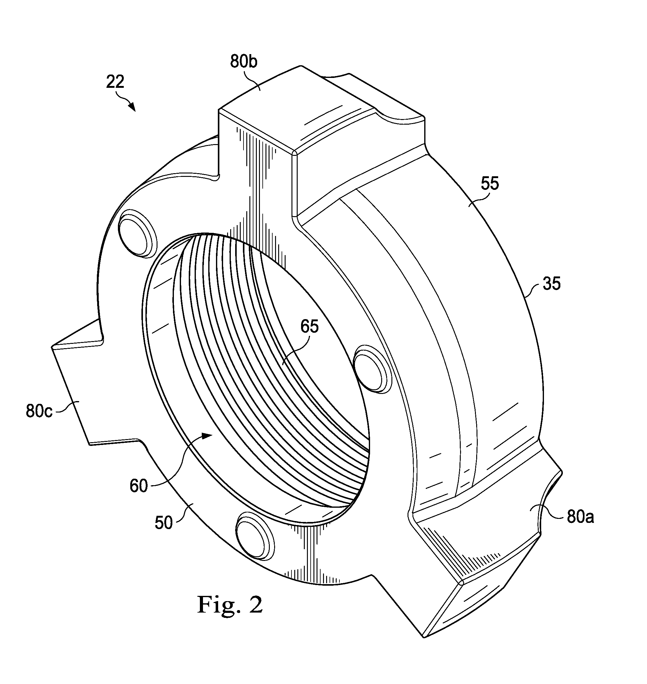
[0029] FIG. 2 is a perspective view of the wing nut of FIG. 1, according to an exemplary embodiment.
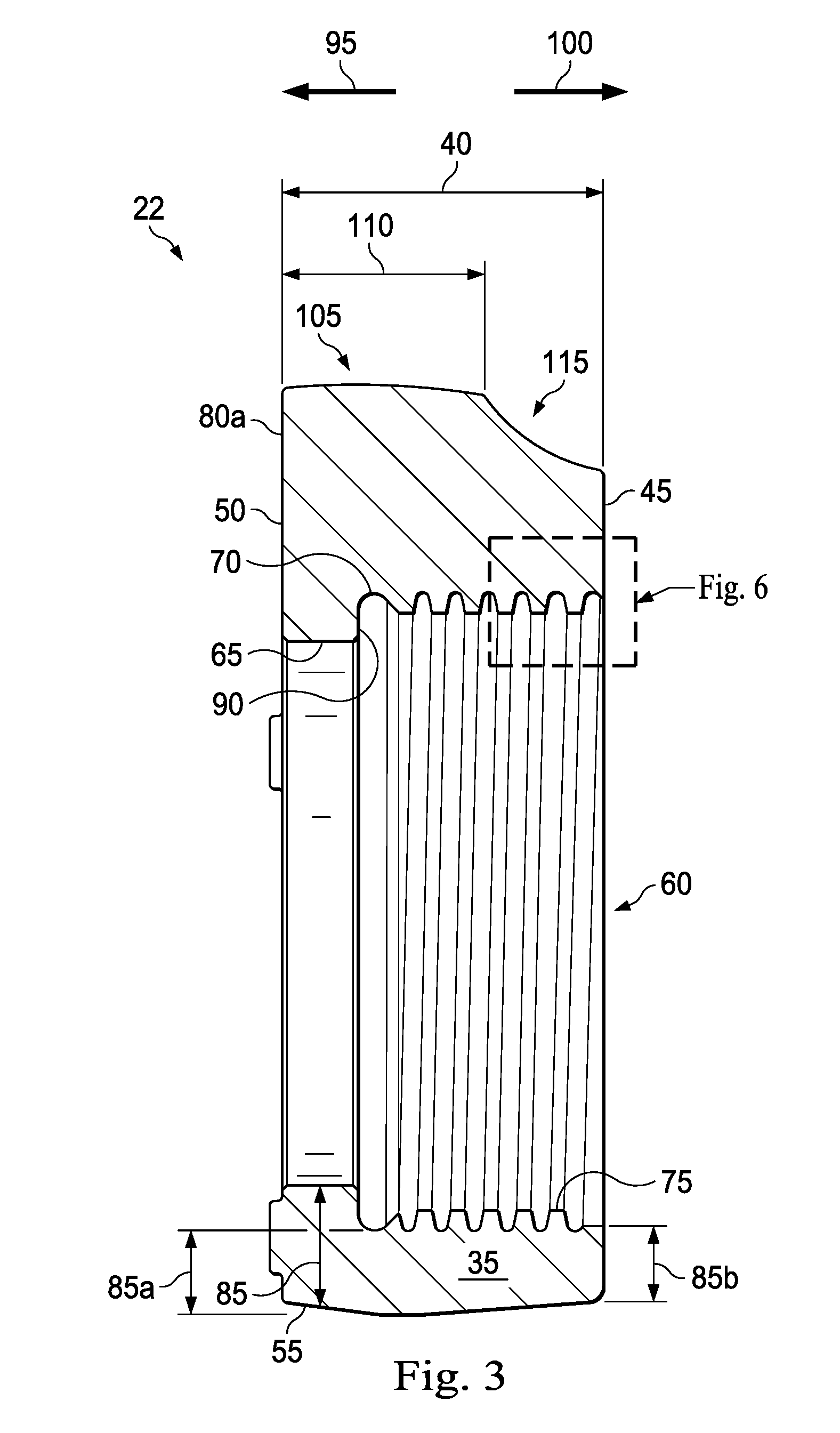
[0030] FIG. 3 is a sectional view of the wing nut of FIG. 2, according to an exemplary embodiment, the wing nut including a threaded connection.
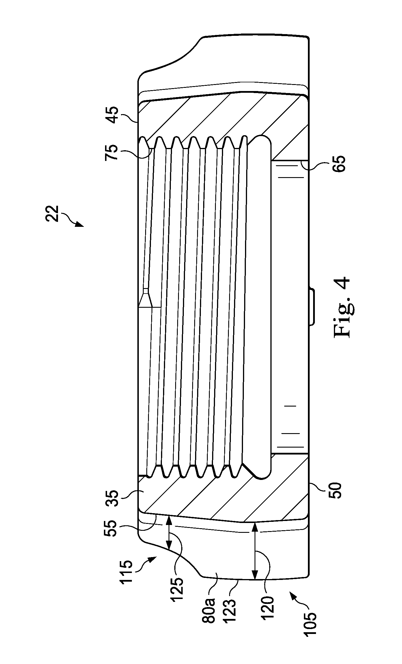
[0031] FIG. 4 is another sectional view of the wing nut of FIG. 2, according to an exemplary embodiment.
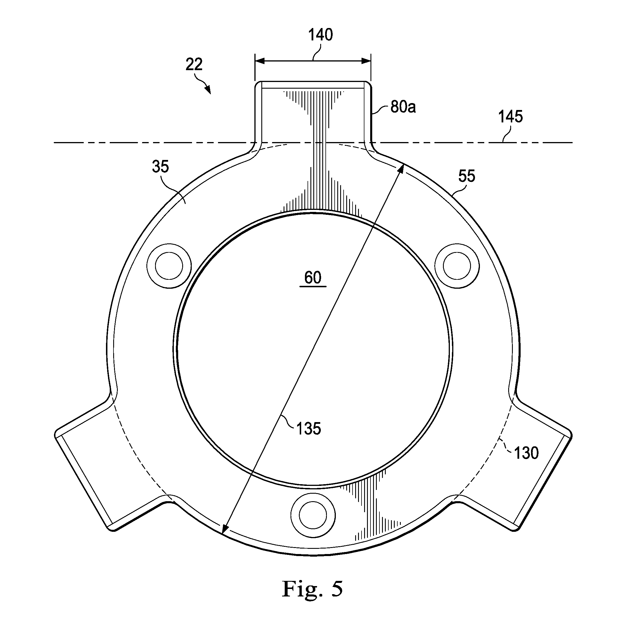
[0032] FIG. 5 is a side view of the wing nut of FIG. 2, according to an exemplary embodiment.
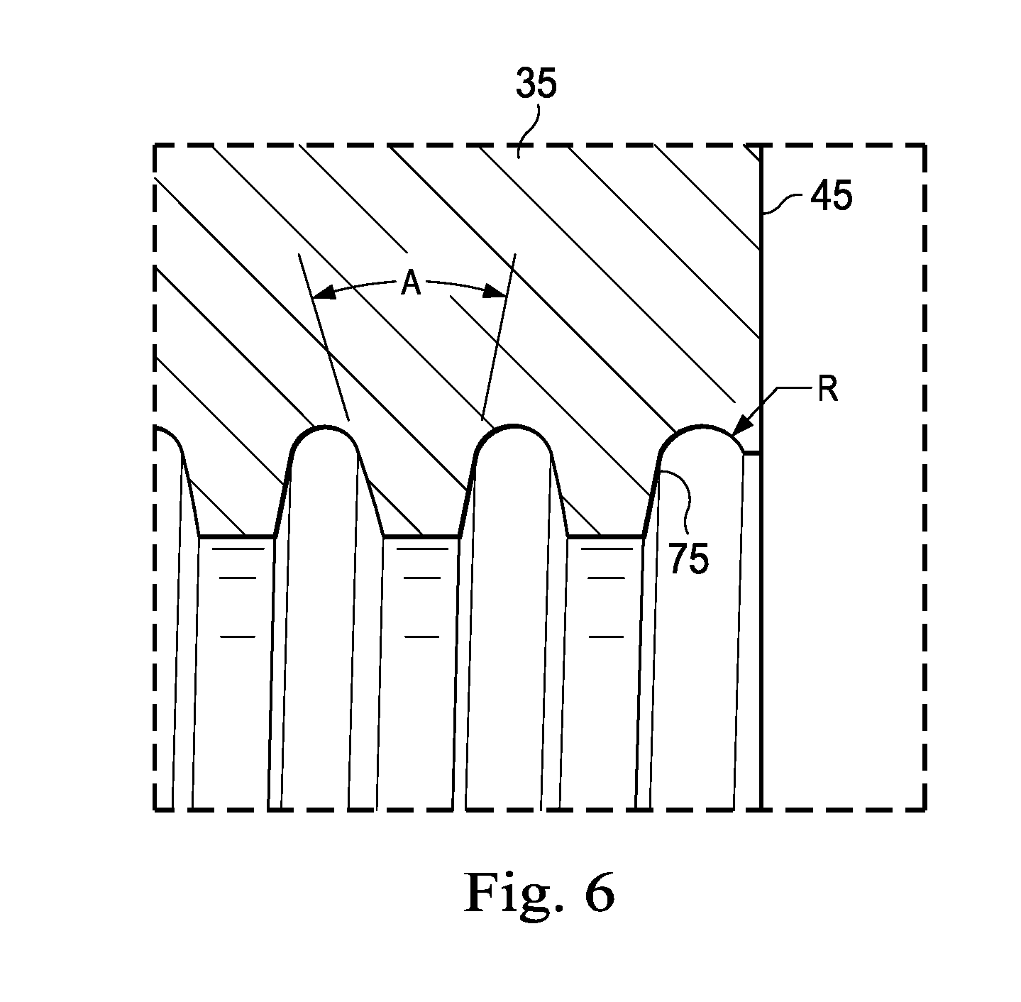
[0033] FIG. 6 is an enlarged portion of the threaded connection of the wing nut of FIG. 3, according to an exemplary embodiment.
[0034] FIG. 7 is a side view of an exemplary embodiment of a wing nut, according to an exemplary embodiment.
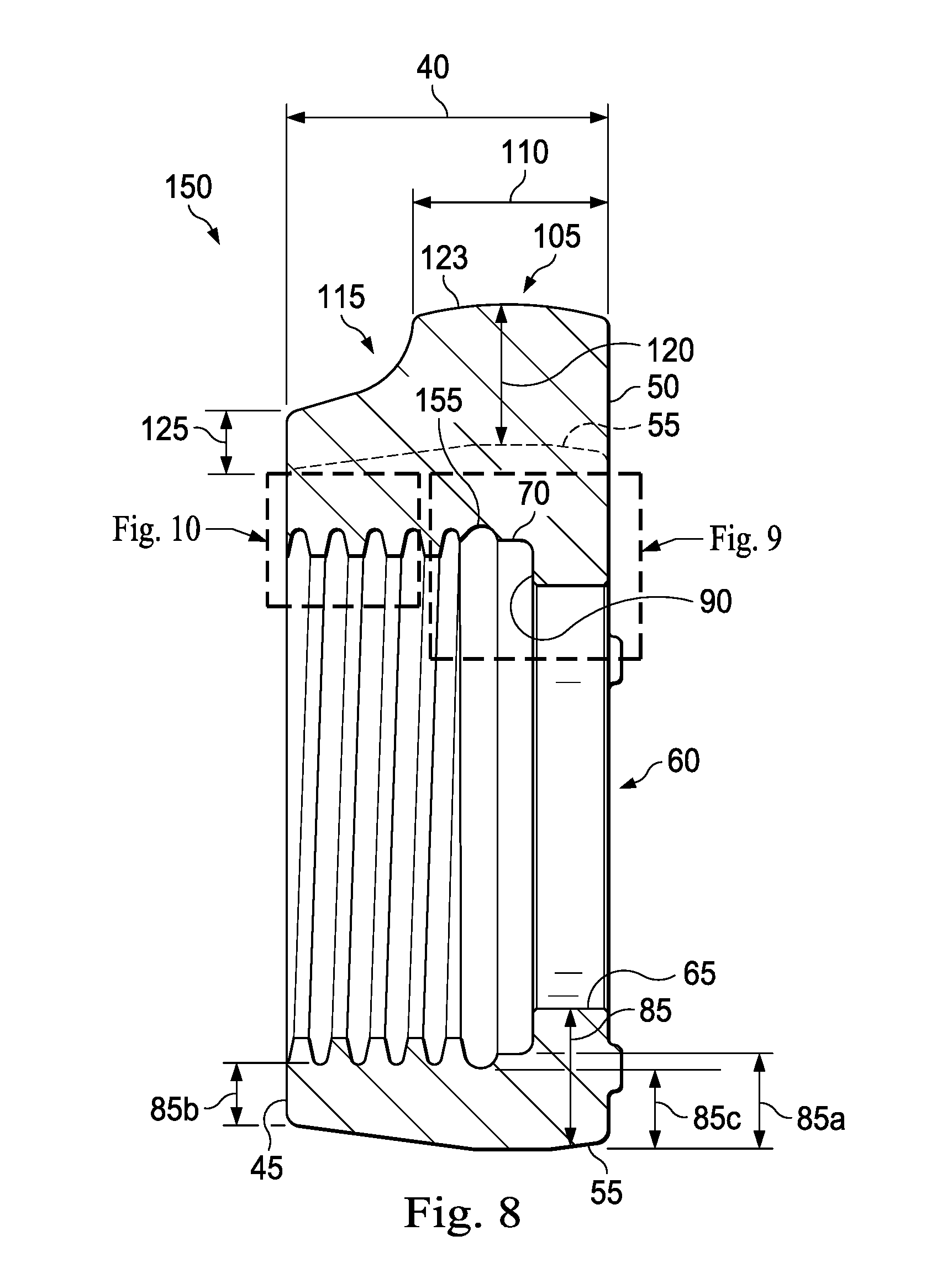
[0035] FIG. 8 is a sectional view of the wing nut of FIG. 7, according to an exemplary embodiment, the wing nut including a threaded connection and a double shoulder.
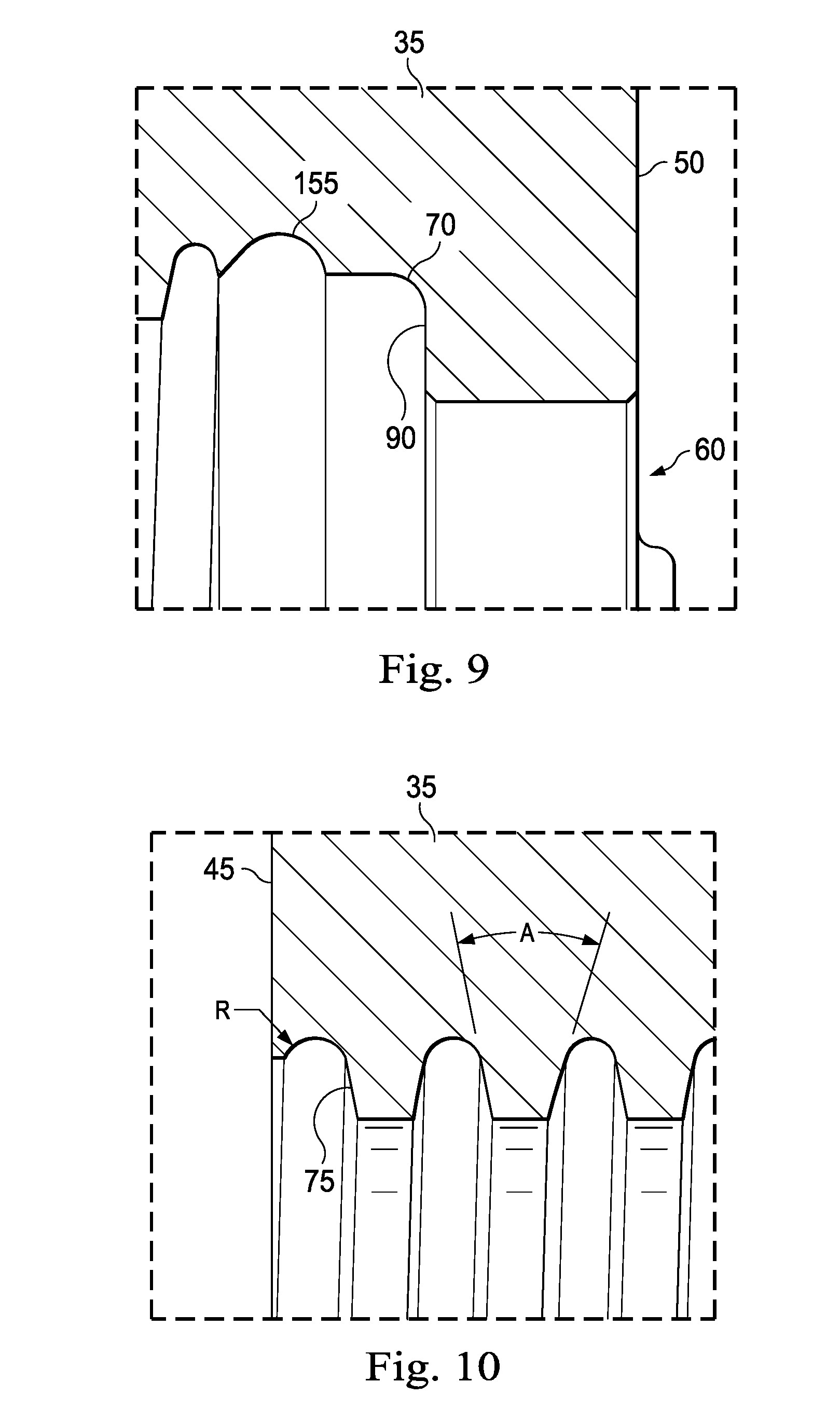
[0036] FIG. 9 is an enlarged view of the double shoulder of the wing nut of FIG. 8, according to an exemplary embodiment.
[0037] FIG. 10 is an enlarged view of the threaded connection of the wing nut of FIG. 8, according to an exemplary embodiment.
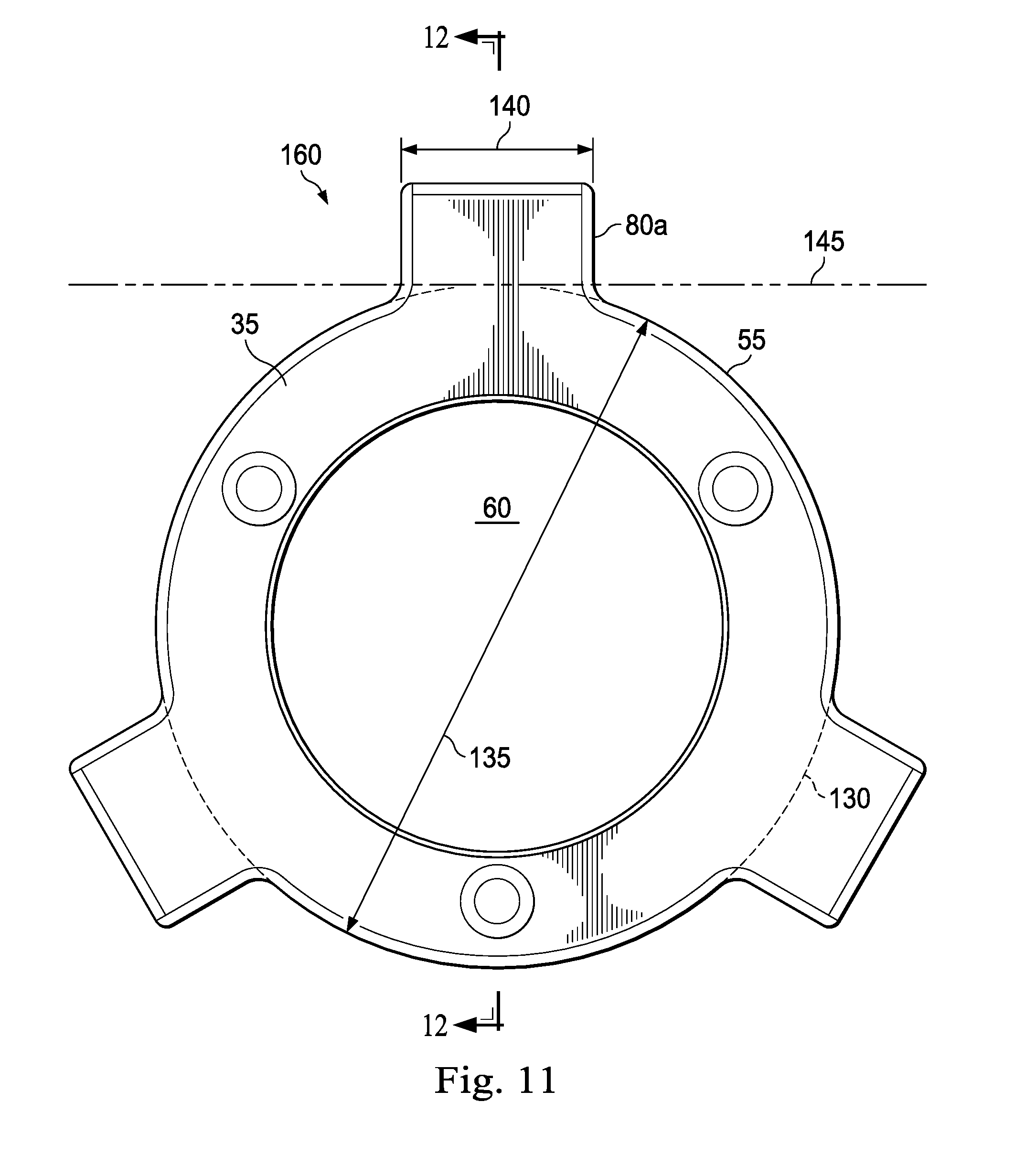
[0038] FIG. 11 is a side view of an exemplary embodiment of a wing nut, according to an exemplary embodiment.
[0039] FIG. 12 is a sectional view of the wing nut of FIG. 11, according to an exemplary embodiment, the wing nut including a threaded connection and a double shoulder.
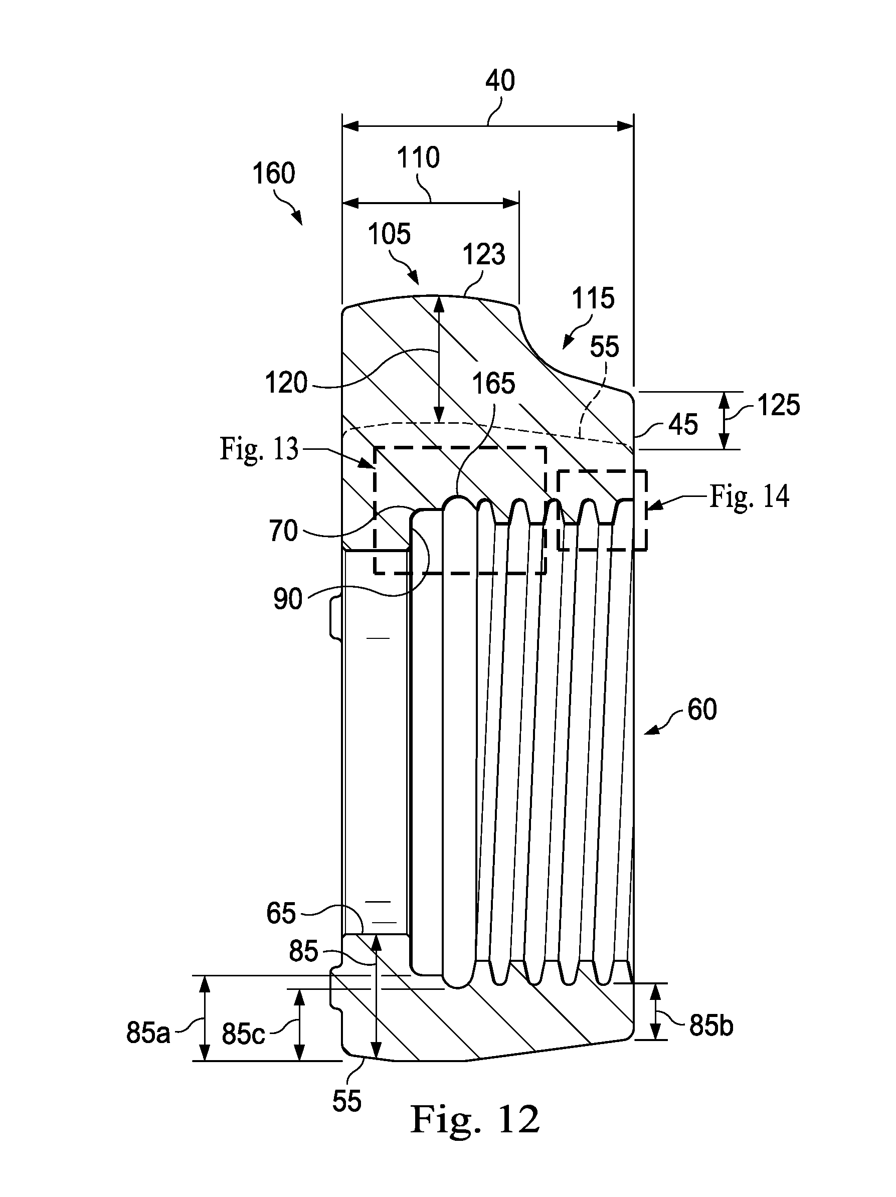
[0040] FIG. 13 is an enlarged view of the double shoulder of the wing nut of FIG. 12, according to an exemplary embodiment.
[0041] FIG. 14 is an enlarged view of the threaded connection of the wing nut of FIG. 12, according to an exemplary embodiment.
[0042] FIG. 15 is a side view of an exemplary embodiment of a wing nut, according to an exemplary embodiment.
[0043] FIG. 16 is a sectional view of the wing nut of FIG. 15, according to an exemplary embodiment, the wing nut including a threaded connection and a shoulder.
[0044] FIG. 17 is an enlarged view of the shoulder of the wing nut of FIG. 16, according to an exemplary embodiment.
[0045] FIG. 18 is an enlarged view of the threaded connection of the wing nut of FIG. 16, according to an exemplary embodiment.
[0046] FIG. 19 is a side view of an exemplary embodiment of a wing nut, according to an exemplary embodiment.
[0047] FIG. 20 is a sectional view of the wing nut of FIG. 19, according to an exemplary embodiment, the wing nut including a threaded connection and a shoulder.
[0048] FIG. 21 is an enlarged view of the shoulder of the wing nut of FIG. 19, according to an exemplary embodiment.
[0049] FIG. 22 is an enlarged view of the threaded connection of the wing nut of FIG. 19, according to an exemplary embodiment.
[0050] FIG. 23 is a side view of an exemplary embodiment of a wing nut, according to an exemplary embodiment.
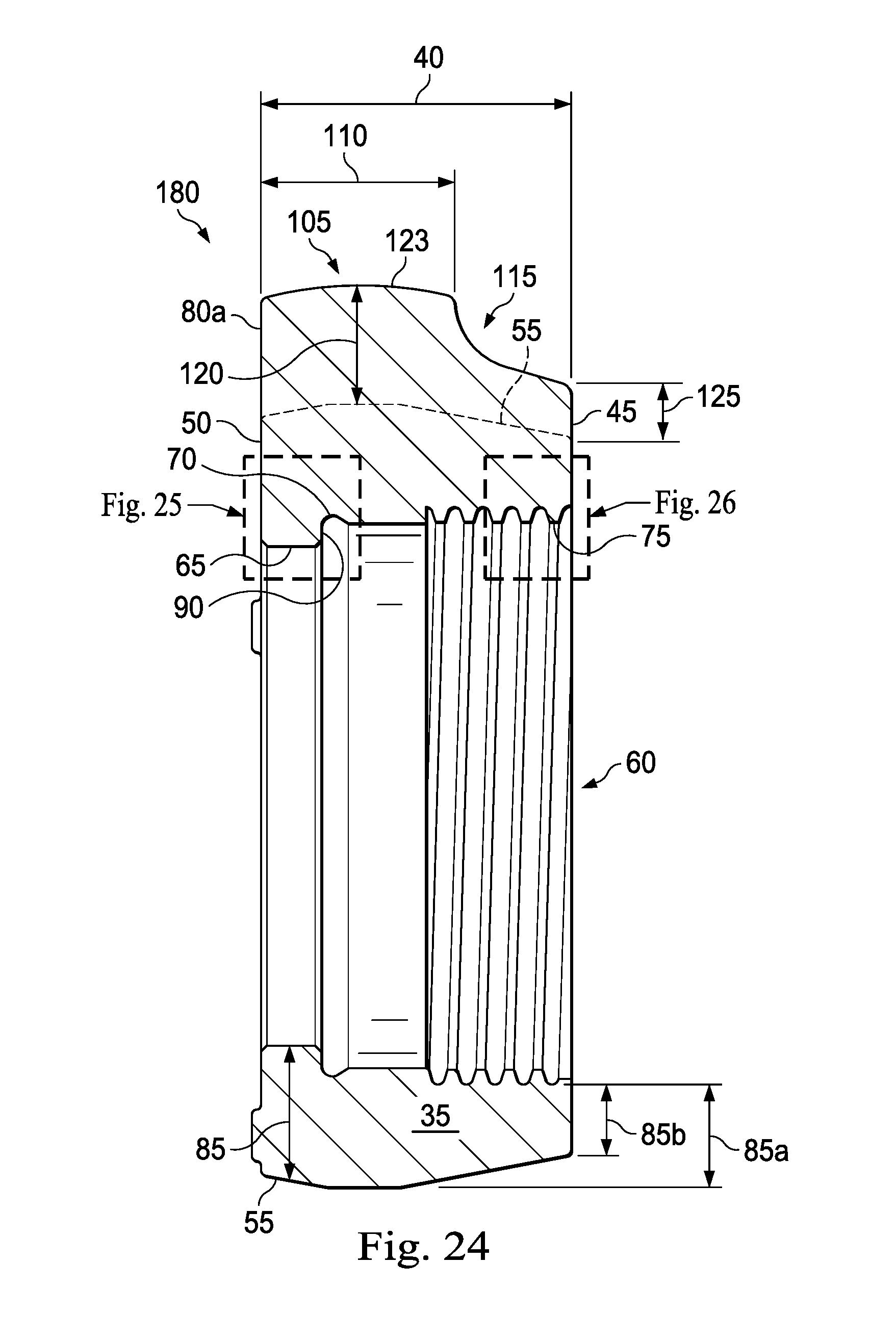
[0051] FIG. 24 is a sectional view of the wing nut of FIG. 23, according to an exemplary embodiment, the wing nut including a threaded connection and a shoulder.
[0052] FIG. 25 is an enlarged view of the shoulder of the wing nut of FIG. 24, according to an exemplary embodiment.
[0053] FIG. 26 is an enlarged view of the threaded connection of the wing nut of FIG. 24, according to an exemplary embodiment.
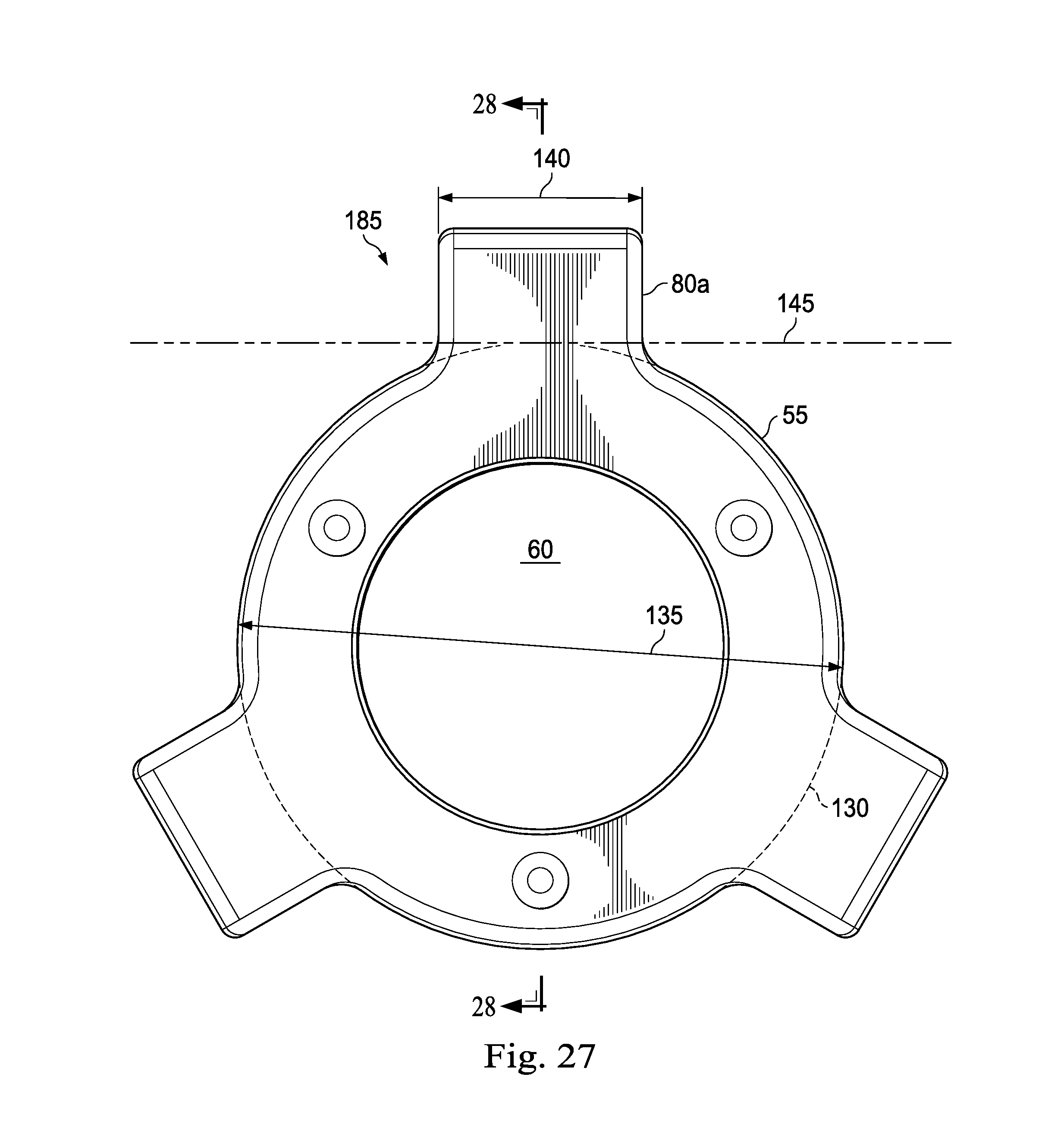
[0054] FIG. 27 is a side view of an exemplary embodiment of a wing nut, according to an exemplary embodiment.
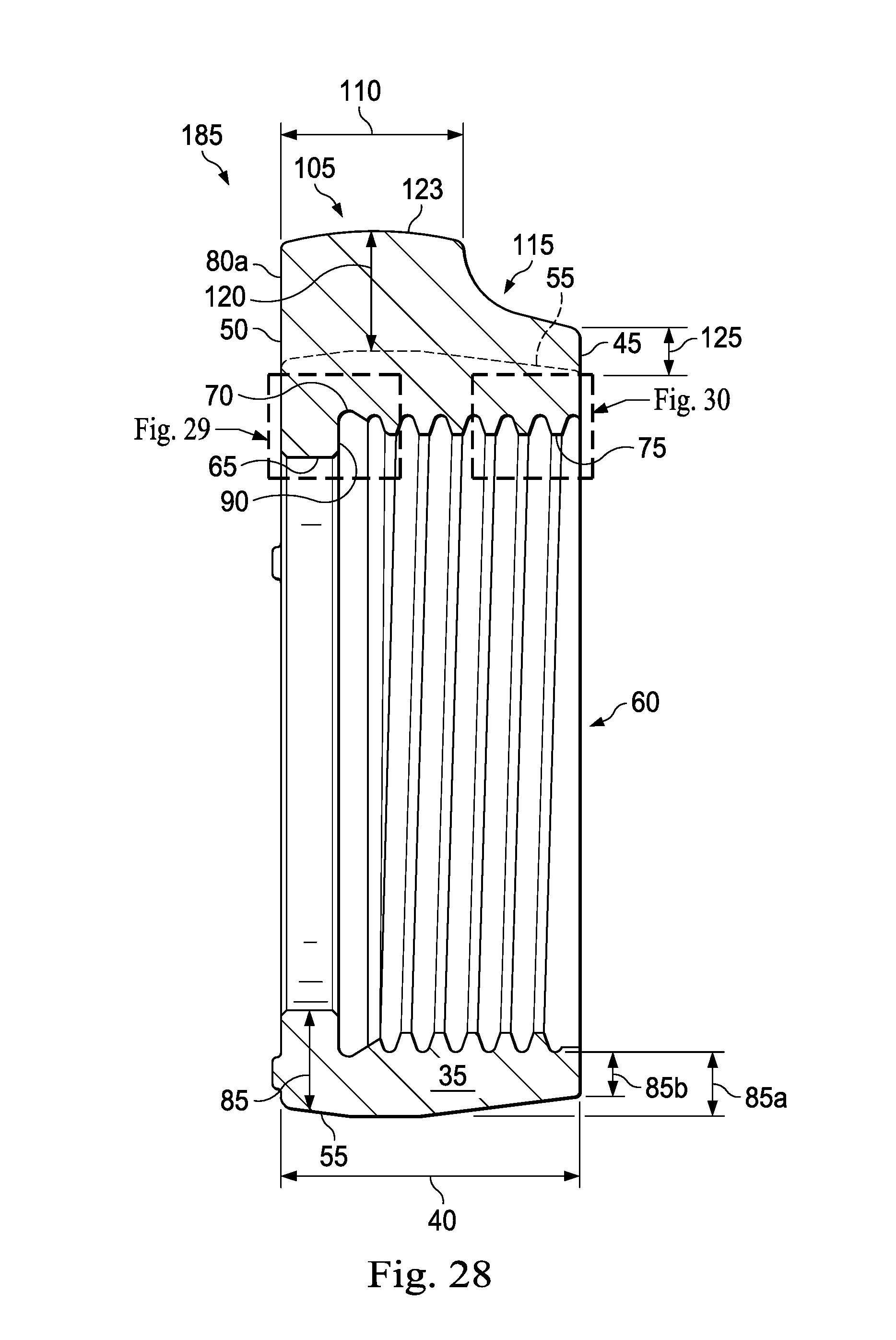
[0055] FIG. 28 is a sectional view of the wing nut of FIG. 27, according to an exemplary embodiment, the wing nut including a threaded connection and a shoulder.
[0056] FIG. 29 is an enlarged view of the shoulder of the wing nut of FIG. 28, according to an exemplary embodiment.
[0057] FIG. 30 is an enlarged view of the threaded connection of the wing nut of FIG. 28, according to an exemplary embodiment.
[0058] FIG. 31 is a side view of an exemplary embodiment of a wing nut, according to an exemplary embodiment.
[0059] FIG. 32 is a sectional view of the wing nut of FIG. 31, according to an exemplary embodiment, the wing nut including a threaded connection and a shoulder.
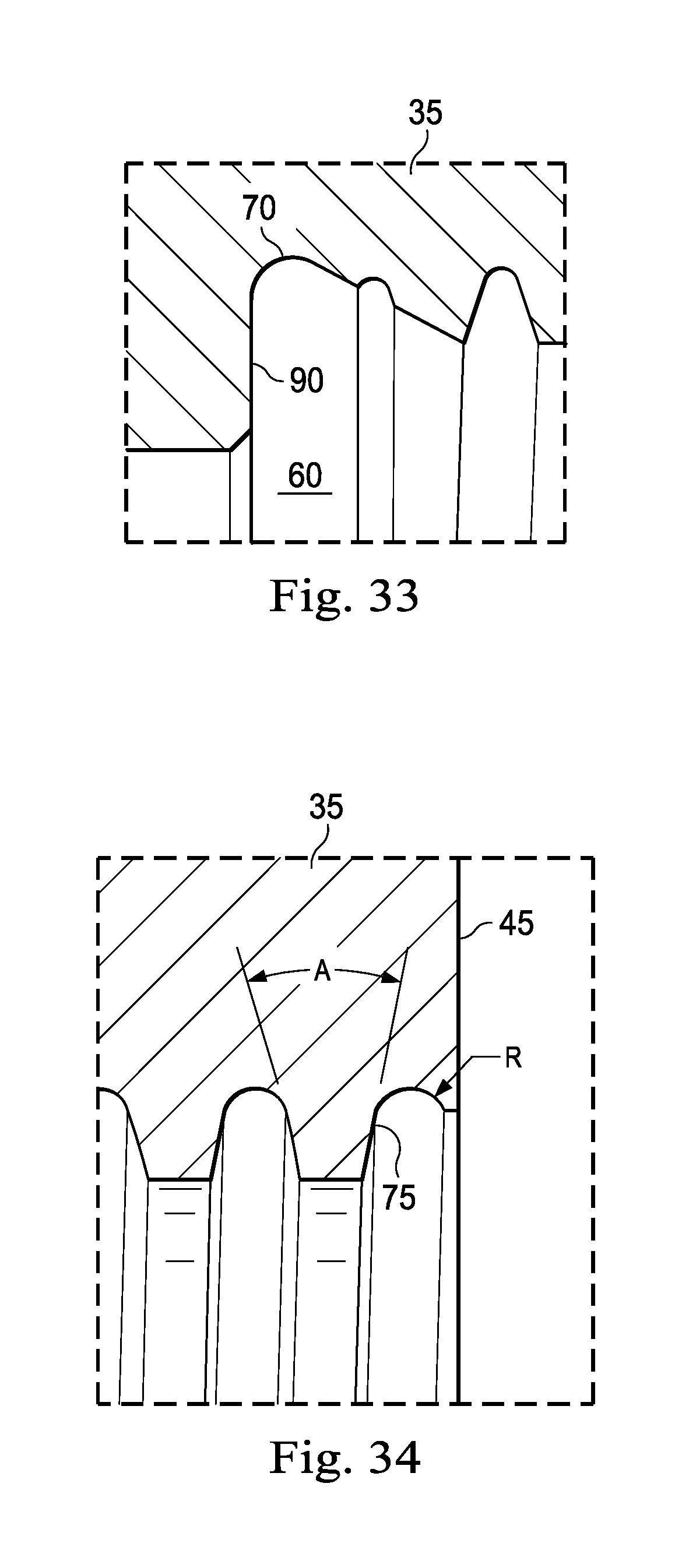
[0060] FIG. 33 is an enlarged view of the shoulder of the wing nut of FIG. 32, according to an exemplary embodiment.
[0061] FIG. 34 is an enlarged view of the threaded connection of the wing nut of FIG. 32, according to an exemplary embodiment.
DETAILED DESCRIPTION
[0062] In an exemplary embodiment, as illustrated in FIG. 1, a hammer union is generally referred to by the reference numeral 10 and includes a male sub 15, a threaded female sub 20, a wing nut 22, a seal ring 25, a plurality of retainer segments 30, and a retainer ring 33. Generally, the female sub 20 is concentrically disposed about the seal ring 25, with the seal ring 25 engaging both the female sub 20 and the male sub 15. Opposing faces of the female sub 20 and male sub 15 are engaged and the plurality of retainer segments 30, which are held together using the retainer ring 33, are concentrically disposed about the male sub 15. The wing nut 22 is concentrically disposed about each of the male sub 15, the plurality of retainer segments 30, the seal ring 25, and the female sub 20 to couple the male sub 15 to the female sub 20.
[0063] As shown in FIGS. 2 and/or 3, the wing nut 22 has a body 35 having an axial length 40 defined between a first end surface 45 and a second end surface 50. The body 35 also has an exterior surface 55 extending between the first and second end surfaces 45 and 50. The wing nut 22 also includes a passage 60 axially extending through the body 35 from the first end surface 45 to the second end surface 50. The passage 60 defines an interior surface 65 of the body 35. An internal shoulder 70 is formed in the body 35 and defines a portion of the passage 60. The wing nut 22 also has an internal threaded connection 75 formed by the interior surface 65 that extends from the first end surface 45 and towards the internal shoulder 70. The wing nut 22 also has circumferentially-spaced lugs 80a, 80b, and 80c extending radially from the exterior surface 55 of the body 35.
[0064] As shown in FIG. 3, the body 35 has a variable wall thickness 85 defined between the interior surface 65 of the body 35 and the exterior surface 55 of the body 35, with a variable wall thickness 85a at the internal shoulder 70 being greater than a variable wall thickness 85b at or near the first end surface 45. In an exemplary embodiment, and when the wing nut 22 is a three (3) inch nominal pipe size wing nut, the variable wall thickness 85a at the internal shoulder is about 0.75 inches and the variable wall thickness 85b at or near the first end surface 45 is about 0.6 inches. However, the variable wall thickness 85a may also be about 0.7 inches and the variable wall thickness 85b at or near the first end surface 45 may be about 0.54 inches. The variable wall thickness 85 may vary along the axial length 40 of the body 35, with the variable wall thickness 85 increased at locations that are expected to experience high stress. For example, the body 35 may form a radially extending face 90 that engages the plurality of retainer segments 30, which may apply a force in the direction indicated by the numeral 95 in FIG. 3 ("the direction 95") to the face 90. Additionally, the female threaded sub 20 engages the threaded connection 75 and may apply a force in the direction indicated by the numeral 100 in FIG. 3 ("the direction 100") to the threaded connection 75 and the wing nut 22. In an exemplary embodiment, cracks often form in the portion of the body 35 that extends between the face 90 and the threaded connection 75. Thus, the variable wall thickness 85 associated with this area may be increased relative to other portions of the body 35 to increase the rigidity of the body 35 and the wing nut 22. Additionally, the variable wall thickness 85b may be greater than a corresponding wall thickness in a conventional wing nut.
[0065] In an exemplary embodiment, the increased wall thickness 85 may prevent failure of the wing nut 22 by preventing cracks or other failures from occurring near the internal threaded connection 75. In an exemplary embodiment, the increased wall thickness 85 reinforces areas within the wing nut 22 that are expected to undergo high stress.
[0066] The outer surface of lug 80a includes a first portion 105 extending in the direction 100 from the second surface 50 by a first portion length 110 and a second portion 115 extending in the direction 95 from the first surface 45 and towards the first portion 105. In an exemplary embodiment the ratio of the axial length 40 of the body 35 to the first portion length 110 is between about one and about three. In an exemplary embodiment, and when the wing nut 22 is a three (3) inch nominal pipe size wing nut, the axial length 40 of the body 35 is about 2.75 inches and the first portion length 110 is about 1.75 such that the ratio is about 1.57. In an exemplary embodiment, the axial length 40 of the body 35 is equal to or substantially equal (within 10%) to the first portion length 110 and a length of the second portion 115. That is, the lug 80a extends along the axial length 40 of the body 35.
[0067] As shown in FIG. 4, the first portion 105 has a thickness 120 defined between the exterior surface 55 of the body 35 and an exterior surface 123 of the lug 80a. Additionally, the second portion 115 has a thickness 125 defined between the exterior surface 55 of the body 35 and the exterior surface 123 of the lug 80a. In an exemplary embodiment, the thickness 125 of the second portion 115 varies from a maximum height at a location where the first portion 105 and the second portion 115 join to a minimum height at the first surface 45. Accordingly, the thickness 125 is equal to or less than the thickness 120. In an exemplary embodiment, the thickness 120 is between about 5 inches to about 1 inch. In an exemplary embodiment, the thickness 120 is between about 1 inch and about 2 inches. In an exemplary embodiment, and when the wing nut 22 is a three (3) inch nominal pipe size wing nut, the thickness 120 is about 1.34 inches. However, the thickness 120 may also be about 1.05 inches. In an exemplary embodiment, the thickness 125 is between about 2.5 inches to about 1 inch. In an exemplary embodiment, the thickness 125 is between about 1 inch and about 0.25 inches. In an exemplary embodiment, the thickness 125 at the first end surface 45 is about 0.5 inches.
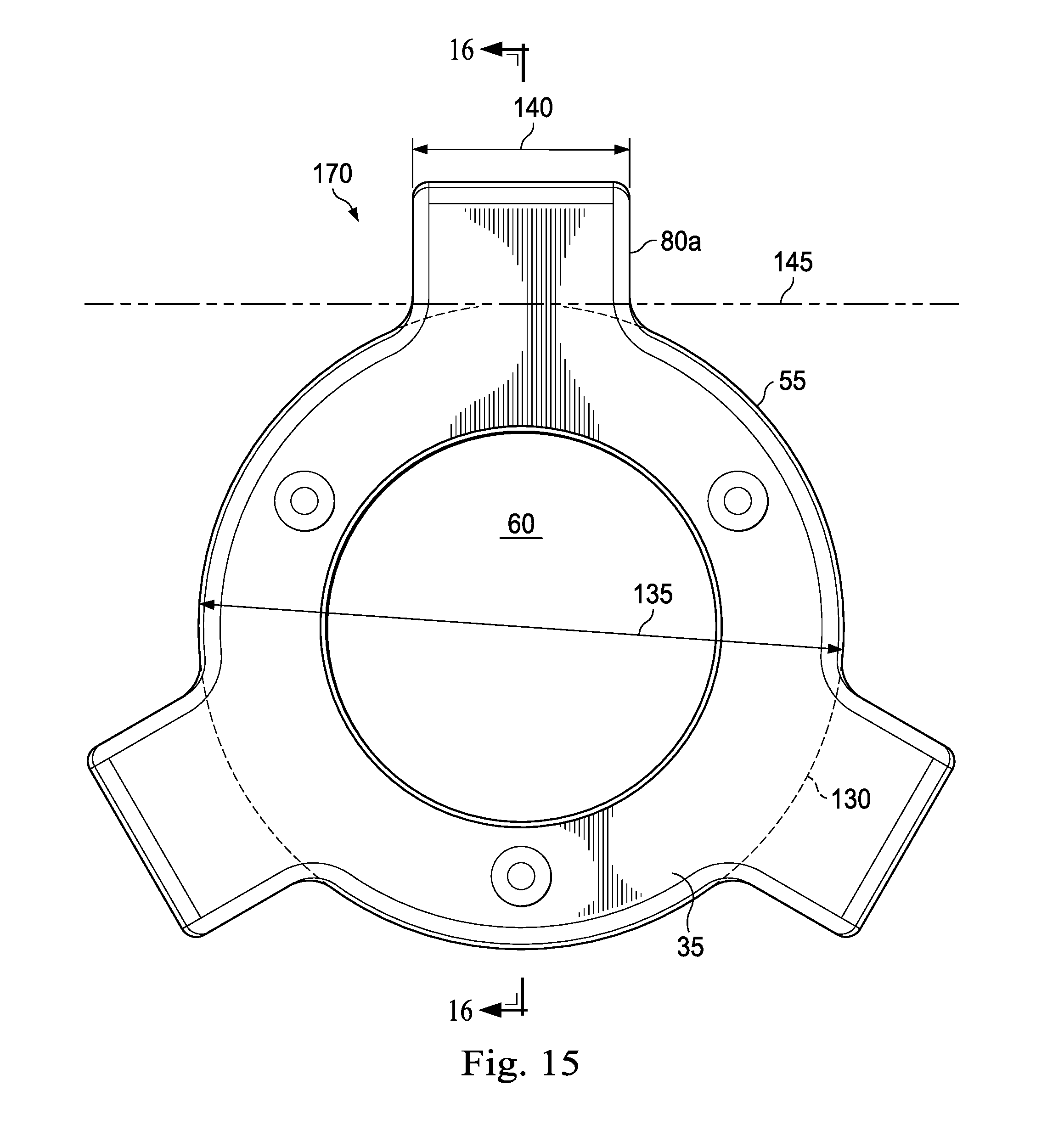
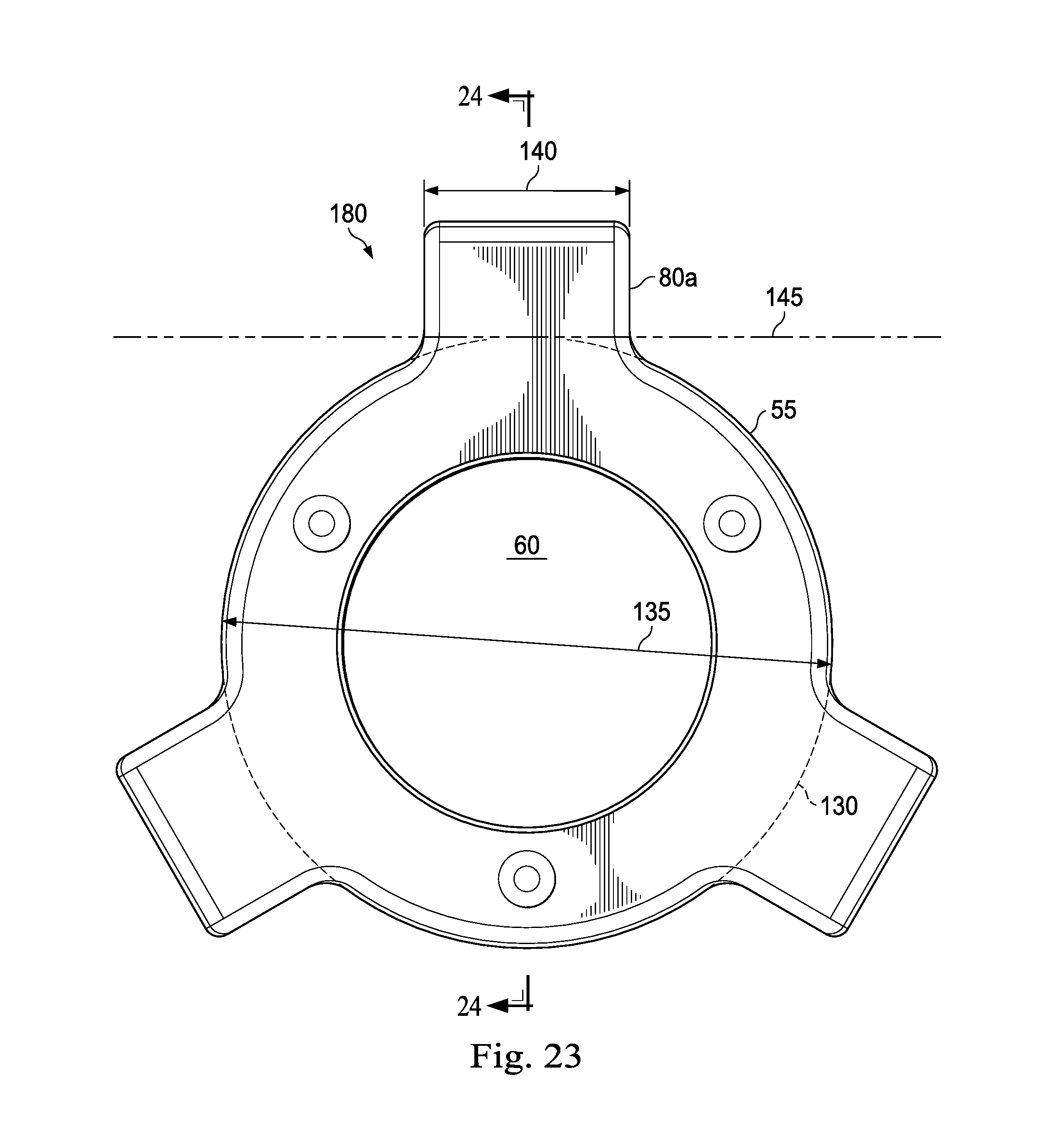
[0068] As shown in FIG. 5, the exterior surface 55 of the body 35 defines an outer circumference 130 and an outer diameter 135. The lug 80a defines a width 140 measured along a line 145 that is tangential to the outer circumference 130 of the body 35. In an exemplary embodiment, the ratio of the outer diameter 135 of the body 35 to the width 140 of the lug 80a is between about 2.5 and about 5.5. In an exemplary embodiment and when the wing nut 22 is a three (3) inch nominal pipe size wing nut, the outer diameter 135 of the body 35 is about 6.9 inches and the width 140 of the lug 80a is about two inches such that the ratio of the outer diameter 135 to the width 140 of the lug 80a is about 3.45.
[0069] As shown in FIG. 6, and when the wing nut 22 is a three (3) inch wing nut, the internal threaded connection 75 has a full-root radius, as indicated as the radius R on FIG. 6, of 0.053 inches. However, the internal threaded connection 75 may have a full-full root radius of 0.06 inches or 0.07 inches. In an exemplary embodiment, the internal threaded connection 75 has a National Acme Thread Form and thus a pitch angle, as indicated as the angle A in FIG. 6, of 29 degrees. In an exemplary embodiment, the internal threaded connection 75 has a National Acme Thread Form and thus a pitch angle of 29 degrees, and has a full-root radius of 0.053 inches. In an exemplary embodiment, the internal threaded connection 75 having a full-root radius reduces the amount of stress experienced in body of the wing nut 22 near the internal threaded connection 75.
[0070] FIGS. 7-10 illustrate an embodiment of a wing nut 150 that is substantially similar to the wing nut 22 and that includes several components of the wing nut 22, which components are given the same reference numerals. In an exemplary embodiment, the wing nut 150 is a three (3) inch nominal pipe size wing nut and includes a second internal shoulder 155 disposed between the threaded connection 75 and the internal shoulder 70. As such, the internal shoulder 155 is formed by the interior surface 65 of the body 35 and defines a portion of the passage 60 that is axially positioned between the internal threaded connection 75 and the internal shoulder 70. Thus, the internal threaded connection 75 formed by the interior surface 65 may extend from the first end surface 45 and towards the internal shoulders 70 and 155. In an exemplary embodiment, the second internal shoulder 155 reduces localized stresses within the wing nut 150 to prevent or at least reduce failure of the wing nut 150. The variable wall thickness 85a of the wing nut 150 at the internal shoulder 70 is about 0.785 inches and the variable wall thickness 85b at or near the first surface 45 is about 0.568 inches. Additionally, a variable wall thickness 85c at the second internal shoulder 155 is about 0.68 inches. Additionally, the axial length 40 of the body 35 is about 2.75 inches and the first portion length 110 is about 1.75 such that the ratio of the axial length 40 to the first portion length 110 is about 1.57. In an exemplary embodiment, the thickness 120 is about 1.05 and the thickness 125 at the first end surface 45 is about 0.48 inches. In an exemplary embodiment, the outer diameter 135 of the body 35 is about 6.9 inches and the width 140 of the lug 80a is about 1.94 inches such that the ratio of the outer diameter 135 to the width 140 of the lug 80a is about 3.55. Moreover, the internal threaded connection 75 has a full-root radius, as indicated as the radius R on FIG. 10, of 0.05 inches. In an exemplary embodiment, the internal threaded connection 75 has a National Acme Thread Form and thus a pitch angle, as indicated as the angle A in FIG. 10, of 29 degrees.
[0071] FIGS. 11-14 illustrate an embodiment of a wing nut 160 that is substantially similar to the wing nut 22 and that includes several components of the wing nut 22, which components are given the same reference numerals. In an exemplary embodiment, the wing nut 160 is a three (3) inch nominal pipe size wing nut and includes a second internal shoulder 165 disposed between the threaded connection 75 and the internal shoulder 70. As such, the internal shoulder 165 is formed by the interior surface 65 of the body 35 and defines a portion of the passage 60 that is axially positioned between the internal threaded connection 75 and the internal shoulder 70. Thus, the internal threaded connection 75 formed by the interior surface 65 may extend from the first end surface 45 and towards the internal shoulders 70 and 165. In an exemplary embodiment, the second internal shoulder 165 reduces localized stresses within the wing nut 160 to prevent or at least reduce failure of the wing nut 160. The variable wall thickness 85a of the wing nut 160 at the internal shoulder 70 is about 0.785 inches and the variable wall thickness 85b at or near the first surface 45 is about 0.54 inches. Additionally, the variable wall thickness 85c at the second internal shoulder 165 is about 0.68 inches. Additionally, the axial length 40 of the body 35 is about 2.75 inches and the first portion length 110 is about 1.75 such that the ratio of the axial length 40 to the first portion length 110 is about 1.57. In an exemplary embodiment, the thickness 120 is about 1.05 and the thickness 125 is about 0.48 inches. In an exemplary embodiment, the outer diameter 135 of the body 35 is about 6.9 inches and the width 140 of the lug 80a is about 1.94 inches such that the ratio of the outer diameter 135 to the width 140 of the lug 80a is about 3.55. Moreover, the internal threaded connection 75 has a full-root radius, as indicated as the radius R on FIG. 14, of 0.05 inches. In an exemplary embodiment, the internal threaded connection 75 has a National Acme Thread Form and thus a pitch angle, as indicated as the angle A in FIG. 14, of 29 degrees.
[0072] FIGS. 15-18 illustrate an embodiment of a wing nut 170 that is substantially similar to the wing nut 22 and that includes several components of the wing nut 22, which components are given the same reference numerals. In an exemplary embodiment, the wing nut 170 is a two (2) inch nominal pipe size wing nut and the variable wall thickness 85a at the internal shoulder is about 0.67 inches and the variable wall thickness 85b at or near the first end surface 45 is about 0.44 inches. Additionally, the axial length 40 of the body 35 is about 2.53 inches and the first portion length 110 is about 1.5 such that the ratio of the axial length 40 to the first portion length 110 is about 1.68. In an exemplary embodiment, the thickness 120 is about 1.06 and the thickness 125 at the first end surface 45 is about 0.42 inches. In an exemplary embodiment, the outer diameter 135 of the body 35 is about 5.6 inches and the width 140 of the lug 80a is about 1.88 inches such that the ratio of the outer diameter 135 to the width 140 of the lug 80a is about 2.97. Moreover, the internal threaded connection 75 has a full-root radius, as indicated as the radius R on FIG. 18, of 0.06 inches. In an exemplary embodiment, the internal threaded connection 75 has a National Acme Thread Form and thus a pitch angle, as indicated as the angle A in FIG. 18, of 29 degrees.
[0073] FIGS. 19-23 illustrate an embodiment of a wing nut 175 that is substantially similar to the wing nut 22 and that includes several components of the wing nut 22, which components are given the same reference numerals. In an exemplary embodiment, the wing nut 175 is a two (2) inch nominal pipe size wing nut and the variable wall thickness 85a at the internal shoulder is about 0.67 inches and the variable wall thickness 85b at or near the first end surface 45 is about 0.44 inches. Additionally, the axial length 40 of the body 35 is about 2.53 inches and the first portion length 110 is about 1.5 such that the ratio of the axial length 40 to the first portion length 110 is about 1.68. In an exemplary embodiment, the thickness 120 is about 1.06 and the thickness 125 at the first end surface 45 is about 0.42 inches. In an exemplary embodiment, the outer diameter 135 of the body 35 is about 5.6 inches and the width 140 of the lug 80a is about 1.88 inches such that the ratio of the outer diameter 135 to the width 140 of the lug 80a is about 2.97. Moreover, the internal threaded connection 75 has a full-root radius, as indicated as the radius R on FIG. 22, of 0.06 inches. In an exemplary embodiment, the internal threaded connection 75 has a National Acme Thread Form and thus a pitch angle, as indicated as the angle A in FIG. 22, of 29 degrees.
[0074] FIGS. 23-26 illustrate an embodiment of a wing nut 180 that is substantially similar to the wing nut 22 and that includes several components of the wing nut 22, which components are given the same reference numerals. In an exemplary embodiment, the wing nut 180 is a four (4) inch nominal pipe size wing nut and the variable wall thickness 85a at the internal shoulder is about 1.31 inches and the variable wall thickness 85b at or near the first end surface 45 is about 0.94 inches. In an exemplary embodiment, the axial length 40 of the body 35 is about 3.63 inches and the first portion length 110 is about 2.25 such that the ratio of the axial length 40 to the first portion length 110 is about 1.61. In an exemplary embodiment, the thickness 120 is about 1.375 inches. In an exemplary embodiment, the thickness 125 at the first end surface 45 is about 0.588 inches. In an exemplary embodiment the outer diameter 135 of the body 35 is about 9.25 inches and the width 140 of the lug 80a is about two (2) inches such that the ratio of the outer diameter 135 to the width 140 of the lug 80a is about 4.6. Moreover, the internal threaded connection 75 has a full-root radius, as indicated as the radius R on FIG. 26, of 0.07 inches. In an exemplary embodiment, the internal threaded connection 75 has a National Acme Thread Form and thus a pitch angle, as indicated as the angle A in FIG. 26, of 29 degrees.
[0075] FIGS. 27-30 illustrate an embodiment of a wing nut 185 that is substantially similar to the wing nut 22 and that includes several components of the wing nut 22, which components are given the same reference numerals. In an exemplary embodiment, the wing nut 185 is a four (4) inch nominal pipe size wing nut the variable wall thickness 85a at the internal shoulder is about 0.605 inches and the variable wall thickness 85b at or near the first end surface 45 is about 0.4 inches. In some exemplary embodiments, the width 140 of the lug 80a may be about 2.13 inches and the outer diameter 135 of the body 35 is about 7.66 inches such that the ratio of the outer diameter 135 to the width 140 is about 3.59. In an exemplary embodiment, the thickness 120 is about 1.17 inches. In an exemplary embodiment, the thickness 125 is about 0.375 inches. In an exemplary embodiment, the axial length 40 of the body 35 is about 3 inches and the first portion length 110 is about 1.75 such that the ratio of the length 40 to the first portion length 110 is about 1.7. Moreover, the internal threaded connection 75 has a full-root radius, as indicated as the radius R on FIG. 30, of 0.07 inches. In an exemplary embodiment, the internal threaded connection 75 has a National Acme Thread Form and thus a pitch angle, as indicated as the angle A in FIG. 30, of 29 degrees.
[0076] FIGS. 31-34 illustrate an embodiment of a wing nut 190 that is substantially similar to the wing nut 22 and that includes several components of the wing nut 22, which components are given the same reference numerals. In an exemplary embodiment, the wing nut 190 is a four (4) inch nominal pipe size wing nut the variable wall thickness 85a at the internal shoulder is about 0.605 inches. In some exemplary embodiments, the width 140 of the lug 80a may be about 2.13 inches and the outer diameter 135 of the body 35 is about 7.66 inches such that the ratio of the outer diameter 135 to the width 140 is about 3.59. In an exemplary embodiment, the thickness 120 is about 1.17 inches. In an exemplary embodiment, the axial length 40 of the body 35 is about 2.25 inches and the first portion length 110 is about 1.75 such that the ratio of the length 40 to the first portion length 110 is about 1.28. Moreover, the internal threaded connection 75 has a full-root radius, as indicated as the radius Ron FIG. 34, of 0.07 inches. In an exemplary embodiment, the internal threaded connection 75 has a National Acme Thread Form and thus a pitch angle, as indicated as the angle A in FIG. 34, of 29 degrees.
[0077] In an exemplary embodiment, the lugs 80a, 80b, and 80c extending along the axial length 40 of the body 35 increases the durability of the wing nuts 22, 150, 160, 170, 175, 180, 185, and 190 and the hammer union 10. Additionally, the lugs 80a, 80b, and 80c having a length that is equal to or substantially equal to (within 10%) of the axial length 40 of the body 35 increases the surface area on which a sledgehammer or other tool may contact the wing nuts 22, 150, 160, 170, 175, 180, 185, and 190 when the hammer union 10 is assembled. Additionally, the thickness and shape of the lugs 80a, 80b, 80c, each of which is described as the outer surface extending along the axial length 40 of the body 35, may increase the number of cycles before the wing nuts 22, 150, 160, 170, 175, 180, 185, and 190 are fatigued, or may increase the fatigue life.
[0078] In an exemplary embodiment, the hammer union 10 is available in a wide range of sizes and in working pressures to 20,000 psi or even 30,000 psi. In an exemplary embodiment, the hammer union 10 provides a pressure-tight, positive seal and is available for standard service and sour gas models. In an exemplary embodiment, the hammer union 10 is used to connect two flow line components in a variety of well service applications, such as for example to connect two flow line components within a hydraulic frac system. However, the hammer union 10 may be used with cementing trucks, a variety of different manifolds (fixed, etc.), a variety of different trailers (e.g., missile, manifold), and high pressure equipment, such as equipment within a hydraulic frac system.
[0079] In the foregoing description of certain embodiments, specific terminology has been resorted to for the sake of clarity. However, the disclosure is not intended to be limited to the specific terms so selected, and it is to be understood that each specific term includes other technical equivalents which operate in a similar manner to accomplish a similar technical purpose. Terms such as "left" and right", "front" and "rear", "above" and "below" and the like are used as words of convenience to provide reference points and are not to be construed as limiting terms.
[0080] In this specification, the word "comprising" is to be understood in its "open" sense, that is, in the sense of "including", and thus not limited to its "closed" sense, that is the sense of "consisting only of'. A corresponding meaning is to be attributed to the corresponding words "comprise", "comprised" and "comprises" where they appear.
[0081] In addition, the foregoing describes only some embodiments of the invention(s), and alterations, modifications, additions and/or changes can be made thereto without departing from the scope and spirit of the disclosed embodiments, the embodiments being illustrative and not restrictive.
[0082] Furthermore, invention(s) have described in connection with what are presently considered to be the most practical and preferred embodiments, it is to be understood that the invention is not to be limited to the disclosed embodiments, but on the contrary, is intended to cover various modifications and equivalent arrangements included within the spirit and scope of the invention(s). Also, the various embodiments described above may be implemented in conjunction with other embodiments, e.g., aspects of one embodiment may be combined with aspects of another embodiment to realize yet other embodiments. Further, each independent feature or component of any given assembly may constitute an additional embodiment.
* * * * *
D00000
D00001
D00002
D00003
D00004
D00005
D00006
D00007
D00008
D00009
D00010
D00011
D00012

D00013
D00014

D00015

D00016

D00017

D00018

D00019
D00020
D00021

D00022
D00023
D00024

D00025

D00026

D00027
XML
uspto.report is an independent third-party trademark research tool that is not affiliated, endorsed, or sponsored by the United States Patent and Trademark Office (USPTO) or any other governmental organization. The information provided by uspto.report is based on publicly available data at the time of writing and is intended for informational purposes only.
While we strive to provide accurate and up-to-date information, we do not guarantee the accuracy, completeness, reliability, or suitability of the information displayed on this site. The use of this site is at your own risk. Any reliance you place on such information is therefore strictly at your own risk.
All official trademark data, including owner information, should be verified by visiting the official USPTO website at www.uspto.gov. This site is not intended to replace professional legal advice and should not be used as a substitute for consulting with a legal professional who is knowledgeable about trademark law.