Pump Device
AKATSUKA; Koichiro ; et al.
U.S. patent application number 15/125837 was filed with the patent office on 2016-12-29 for pump device. This patent application is currently assigned to KYB Corporation. The applicant listed for this patent is KYB Corporation. Invention is credited to Koichiro AKATSUKA, Tomoyuki FUJITA, Hiroki GOMI, Fumiyasu KATOU, Tomoyuki NAKAGAWA.
| Application Number | 20160377078 15/125837 |
| Document ID | / |
| Family ID | 55533095 |
| Filed Date | 2016-12-29 |


| United States Patent Application | 20160377078 |
| Kind Code | A1 |
| AKATSUKA; Koichiro ; et al. | December 29, 2016 |
PUMP DEVICE
Abstract
A pump device includes a pump, a flow control valve having a spool that returns a part of working fluid discharged from the pump to a suction side, and a differential pressure adjusting device that adjusts a differential pressure acting on both end portions of the spool to a target differential pressure, and the differential pressure adjusting device includes a pressure regulating chamber that communicates with a second fluid pressure chamber and a pilot chamber into which pressure in the discharge channel is guided: and a pressure in the pressure regulating chamber is adjusted such that a differential pressure between the pressure in the pressure regulating chamber and a pressure in the pilot chamber becomes the target differential pressure.
| Inventors: | AKATSUKA; Koichiro; (Gifu, JP) ; FUJITA; Tomoyuki; (Gifu, JP) ; NAKAGAWA; Tomoyuki; (Gifu, JP) ; KATOU; Fumiyasu; (Aichi, JP) ; GOMI; Hiroki; (Gifu, JP) | ||||||||||
| Applicant: |
|
||||||||||
|---|---|---|---|---|---|---|---|---|---|---|---|
| Assignee: | KYB Corporation Tokyo JP |
||||||||||
| Family ID: | 55533095 | ||||||||||
| Appl. No.: | 15/125837 | ||||||||||
| Filed: | September 2, 2015 | ||||||||||
| PCT Filed: | September 2, 2015 | ||||||||||
| PCT NO: | PCT/JP2015/074984 | ||||||||||
| 371 Date: | September 13, 2016 |
| Current U.S. Class: | 417/310 |
| Current CPC Class: | F04C 14/26 20130101; F04C 2/3446 20130101; F04C 2270/215 20130101; F04C 15/06 20130101; F04C 2240/10 20130101; F04C 2270/86 20130101; F04C 2270/585 20130101; F04C 2210/206 20130101; F04C 2240/20 20130101 |
| International Class: | F04C 14/26 20060101 F04C014/26; F04C 15/06 20060101 F04C015/06; F04C 2/344 20060101 F04C002/344 |
Foreign Application Data
| Date | Code | Application Number |
|---|---|---|
| Sep 16, 2014 | JP | 2014-187279 |
Claims
1. A pump device for supplying working fluid to a fluid pressure apparatus comprising: a pump configured to discharge the working fluid into a discharge channel by sucking and pressurizing the working fluid; a flow control valve having a first valve body configured to operate in accordance with a differential pressure acting on both end portions thereof to return a part of the working fluid discharged from the pump to a suction side; and a differential pressure adjusting device configured to adjust the differential pressure acting on both end portions of the first valve body to a target differential pressure; wherein the flow control valve comprises: a first fluid pressure chamber provided so as to face against a first-side end portion of the first valve body, the first fluid pressure chamber communicating with the discharge channel; a second fluid pressure chamber provided so as to face against a second-side end portion of the first valve body, the second fluid pressure chamber communicating with the discharge channel; and a biasing member accommodated in the second fluid pressure chamber in a compressed state, the biasing member being configured to bias the first valve body in a valve-closing direction; and the differential pressure adjusting device has: a second valve body; a pressure regulating chamber provided so as to face against a first-side end portion of the second valve body, the pressure regulating chamber communicating with the second fluid pressure chamber; and a pilot chamber provided so as to face against a second-side end portion of the second valve body, a pressure in the discharge channel being guided into the pilot chamber; and wherein a pressure in the pressure regulating chamber is adjusted such that a differential pressure between the pressure in the pressure regulating chamber and a pressure in the pilot chamber becomes the target differential pressure.
2. The pump device according to claim 1, wherein the pump device further comprises an orifice provided in a communicating passage that allows the discharge channel to communicate with the second fluid pressure chamber.
3. The pump device according to claim 1, wherein the differential pressure adjusting device further comprises: a biasing member accommodated in the pressure regulating chamber in a compressed state, the biasing member being configured to bias the second valve body in a valve-opening direction; and a proportional solenoid configured to bias the second valve body in the valve-closing direction, the proportional solenoid being capable of changing the biasing force biasing the second valve body in the valve-closing direction.
4. The pump device according to claim 1, wherein the target differential pressure is adjusted in accordance with a rotation speed of the pump.
5. The pump device according to claim 1, wherein the target differential pressure is adjusted in accordance with pressure required by the fluid pressure apparatus.
Description
TECHNICAL FIELD
[0001] The present invention relates to a pump device.
BACKGROUND ART
[0002] In the related art, there are known pump devices, in which a flow control valve is provided in order to keep a discharge flow amount of the pump constant.
[0003] JP05-61482U describes a pump device in which a flow control valve is provided at an intermediate position in a drain passage that is connected between a suction passage and a discharge passage of a vane pump. With the pump device described in JP05-61482U, working oil discharged from pump chambers to the discharge passage in a manner proportional to the rotation speed of the pump is supplied to a hydraulic driving device through an orifice. In addition, with the pump device described in JP05-61482U, the flow control valve is controlled so as to be opened/closed such that the amount of the working oil supplied from the vane pump to the hydraulic driving device is controlled so as to be substantially constant.
SUMMARY OF INVENTION
[0004] However, with the pump device in JP05-61482U, a restrictor is provided in the discharge passage of the pump. Therefore, a pressure loss is caused at the restrictor, and torque required for driving the pump becomes correspondingly greater.
[0005] The present invention has been conceived in light of the problems mentioned above, and an object thereof is to provide a pump device capable of controlling a flow amount while reducing a driving torque for a pump.
[0006] According to one aspect of the present invention, a pump device for supplying working fluid to a fluid pressure apparatus includes: a pump configured to discharge the working fluid into a discharge channel by sucking and pressurizing the working fluid; a flow control valve having a first valve body configured to operate in accordance with a differential pressure acting on both end portions thereof to return a part of the working fluid discharged from the pump to a suction side; and a differential pressure adjusting device configured to adjust the differential pressure acting on both end portions of the first valve body to a target differential pressure; wherein the flow control valve comprises: a first fluid pressure chamber provided so as to face against a first-side end portion of the first valve body, the first fluid pressure chamber communicating with the discharge channel; a second fluid pressure chamber provided so as to face against a second-side end portion of the first valve body, the second fluid pressure chamber communicating with the discharge channel; and a biasing member accommodated in the second fluid pressure chamber in a compressed state, the biasing member being configured to bias the first valve body in a valve-closing direction; and the differential pressure adjusting device has: a second valve body; a pressure regulating chamber provided so as to face against a first-side end portion of the second valve body, the pressure regulating chamber communicating with the second fluid pressure chamber; and a pilot chamber provided so as to face against a second-side end portion of the second valve body, a pressure in the discharge channel being guided into the pilot chamber; and wherein a pressure in the pressure regulating chamber is adjusted such that a differential pressure between the pressure in the pressure regulating chamber and a pressure in the pilot chamber becomes the target differential pressure.
BRIEF DESCRIPTION OF DRAWINGS
[0007] FIG. 1 is a hydraulic circuit diagram of a pump device according to a first embodiment of the present invention.
[0008] FIG. 2 is a map showing the relationship between the pump rotation speed at a certain target flow amount and the target differential pressure.
[0009] FIG. 3 is a map showing the relationship between the target differential pressure and the current applied to a proportional solenoid.
[0010] FIG. 4 is a map showing the relationship between the pump rotation speed at a certain target flow amount and the target differential pressure for a pump device according to a second embodiment of the present invention.
DESCRIPTION OF EMBODIMENTS
First Embodiment
[0011] A pump device 100 according to a first embodiment of the present invention will be described below with reference to the drawings.
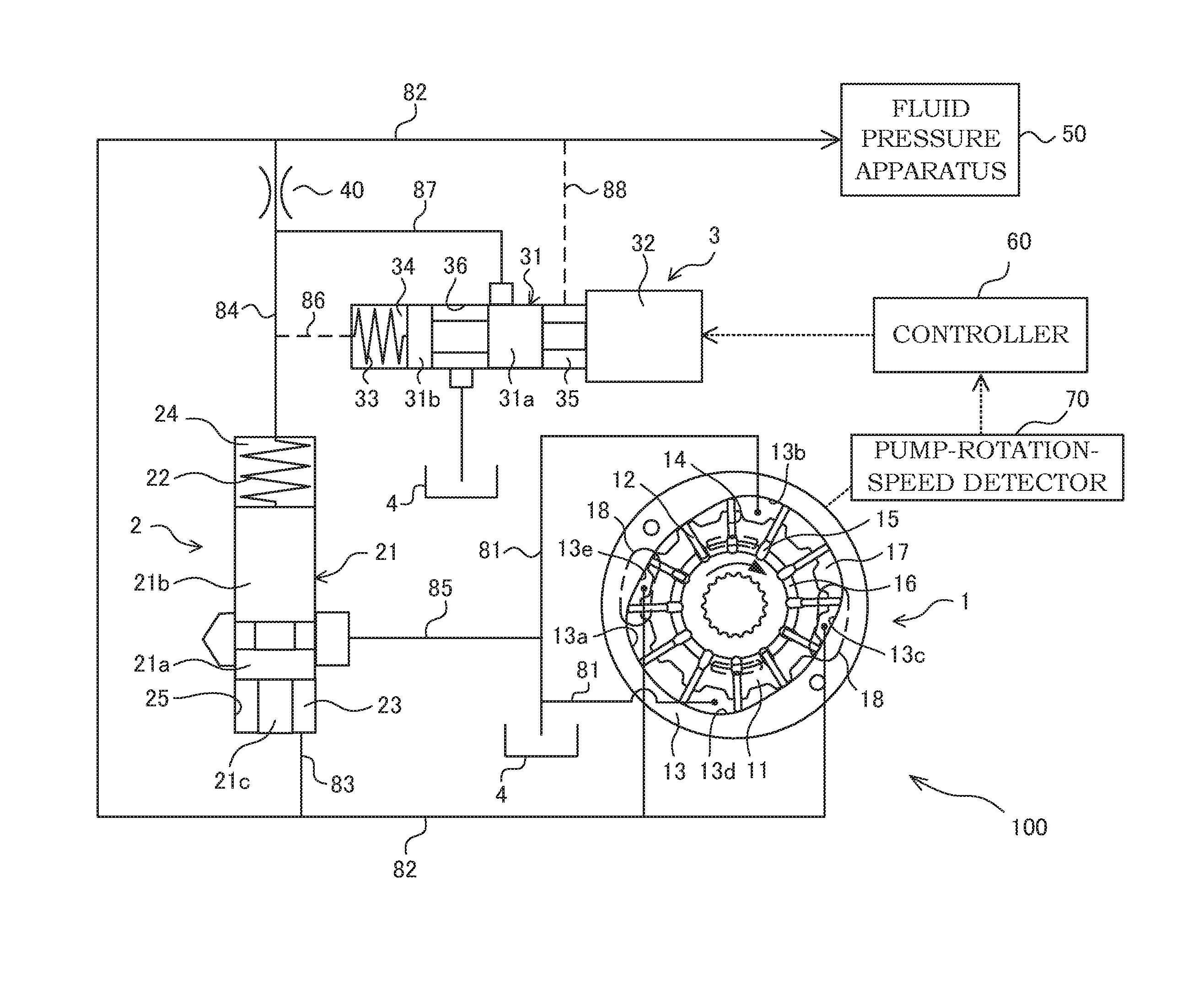
[0012] FIG. 1 is a hydraulic circuit diagram of the pump device 100. The pump device 100 includes a pump 1 in which working oil serving as working fluid is sucked from a suction channel 81 connected to a tank 4 and in which the working oil is pressurized and discharged to a discharge channel 82 and a flow control valve 2 having a spool 21 serving as a first valve body that operates in accordance with the differential pressure acting on both end portions thereof in such a mariner that a part of the working fluid discharged from the pump 1 is returned to the suction channel 81 on the suction side.
[0013] The pump 1 is a fixed displacement vane pump. The pump 1 includes a rotor 11 that is rotationally driven by a driving device, such as an engine (not shown), a plurality of vanes 12 that are provided so as to be movable in a reciprocating manner in the radial direction with respect to the rotor 11, and a cam ring 13 in which the rotor 11 is accommodated and tip ends of the vanes 12 are brought into sliding contact with a cam face 13a on the inner circumference thereof by rotation of the rotor 11.
[0014] In the rotor 11, slits 14 having openings in an outer circumferential surface are formed in a radiating pattern with predetermined gaps therebetween, and the vanes 12 are respectively inserted into the slits 14 in a freely slidable manner.
[0015] At base-end sides of the slits 14, back pressure chambers 15 into which discharge pressure of the pump 1 is guided are defined. The adjacent back pressure chambers 15 communicate with each other through an arc-shaped groove 16 formed in the rotor 11, and the pump discharge pressure is constantly guided to the groove 16. The vanes 12 are pushed in the directions in which the vanes 12 project out from the slits 14 by the pressure in the back pressure chambers 15 and the centrifugal force caused by the rotation of the rotor 11, and thereby, the tip ends of the vanes 12 are brought into contact with the cam face 13a on the inner circumference of the cam ring 13. With such a configuration, a plurality of pump chambers 17 are defined within the cam ring 13 by the outer circumferential surface of the rotor 11, the cam face 13a of the cam ring 13, and pairs of adjacent vanes 12.
[0016] The cam ring 13 is an annular member whose circumferential cam face 13a on the inner circumference has a substantially oval shape, and the cam ring 13 has suction regions 13b and 13d in which the volume of the pump chambers 17 are expanded as the rotor 11 is rotated and discharge regions 13c and 13e in which the volume of the pump chambers 17 are contracted as the rotor 11 is rotated.
[0017] While the rotor 11 is fully rotated, the respective pump chambers 17 suck the working oil from the suction channel 81 through a suction port (not shown) in the suction region 13b of the cam ring 13, discharge the sucked working oil to the discharge channel 82 through a discharge port 18 of the discharge region 13c of the cam ring 13, subsequently suck the working oil from the suction channel 81 through the suction port (not shown) in the suction region 13d of the cam ring 13, and discharge the sucked working oil to the discharge channel 82 through the discharge port 18 in the discharge region 13e of the cam ring 13. As described above, the respective pump chambers 17 are expanded/contracted by the rotation of the rotor 11, and the working oil is sucked/discharged twice while the rotor 11 is fully rotated. The pump rotation speed N of the pump 1 changes in accordance with the rotation speed of the driving device. As the pump rotation speed N is increased, the discharge flow amount of the pump 1 is increased in a manner proportional to the rotation speed.
[0018] As long as the pump 1 is of a rotationally-operated fixed displacement type, the pump 1 may be of any type, such as a gear pump.
[0019] The flow control valve 2 includes the spool 21 that is inserted into a valve accommodating bore 25 in a freely slidable manner, a first fluid pressure chamber 23 that is provided so as to face against a first-side end portion of the spool 21, a second fluid pressure chamber 24 that is provided so as to face against a second-side end portion of the spool 21, and a return spring 22 serving as a biasing member accommodated in the second fluid pressure chamber 24 in a compressed state for biasing the spool 21 in the valve-closing direction.
[0020] The spool 21 includes a first land part 21a and a second land part 21b that slide along the inner circumferential surface of the valve accommodating bore 25.
[0021] In the first fluid pressure chamber 23, a first stopper portion 21c is arranged by being connected to the first land part 21a so as to be brought into contact with a bottom portion of the valve accommodating bore 25 when the spool 21 is moved in the direction in which the volume of the first fluid pressure chamber 23 is contracted and so as to restrict the movement of the spool 21 exceeding a predetermined amount.
[0022] A first communicating passage 83, which is branched off from the discharge channel 82, is connected to the first fluid pressure chamber 23 and a second communicating passage 84, which is branched off from the discharge channel 82, is connected to the second fluid pressure chamber 24. In addition, a drain passage 85, which is communicated with or shut off from the first fluid pressure chamber 23 by the first land part 21a, is connected to the flow control valve 2.
[0023] The spool 21 is stopped at a position where the load exerted by the pressure of the working oil guided to the first fluid pressure chamber 23 and the second fluid pressure chamber 24, which are defined at both end portions thereof, and the biasing force by the return spring 22 are balanced.
[0024] When the total load, acting on the spool 21, of the load exerted by the pressure P2 in the second fluid pressure chamber 24 and the biasing force by the return spring 22 is greater than the load exerted by the pressure P1 in the first fluid pressure chamber 23 acting on the spool 21, the return spring 22 is extended and the spool 21 is in a state in which the first stopper portion 21c is in contact with the bottom portion of the valve accommodating bore 25.
[0025] In this state, the first land part 21a of the spool 21 shuts off the communication between the first fluid pressure chamber 23 and the drain passage 85. Thus, all of the working oil discharged from the pump 1 is supplied to a fluid pressure apparatus 50.
[0026] In contrast, when the load exerted by the pressure P1 in the first fluid pressure chamber 23 acting on the spool 21 is greater than the total load, acting on the spool 21, of the load exerted by the pressure P2 in the second fluid pressure chamber 24 and the biasing force by the return spring 22, the spool 21 is moved against the biasing force by the return spring 22.
[0027] In this state, the first land part 21a of the spool 21 allows communication between the first fluid pressure chamber 23 and the drain passage 85. Thus, a part of the working oil discharged from the pump 1 is returned to the suction channel 81 through the first fluid pressure chamber 23 and the drain passage 85.
[0028] As described above, the flow control valve 2 operates in accordance with the differential pressure acting on both end portions of the spool 21. Therefore, by controlling the differential pressure acting on both end portions of the spool 21, it is possible to control the flow amount of the working oil returning to the suction channel 81 through the flow control valve 2, and it is possible to control the flow amount of the working oil supplied to the fluid pressure apparatus 50 from the pump 1 so as to become the desirable flow amount.
[0029] The pump device 100 further includes a differential pressure adjusting device 3 that adjusts the differential pressure Pd, acting on both end portions of the spool 21 of the flow control valve 2, between the pressure P1 in the first fluid pressure chamber 23 and the pressure P2 in the second fluid pressure chamber 24 to a target differential pressure Pt and an orifice 40 that is provided in the second communicating passage 84 communicating the discharge channel 82 and the second fluid pressure chamber 24.
[0030] The differential pressure adjusting device 3 includes a spool 31 serving as a second valve body, a pressure regulating chamber 34 that is provided so as to face against a first-side end portion of the spool 31 and that communicates with the second fluid pressure chamber 24, a pilot chamber 35 that is provided so as to face against a second-side end portion of the spool 31 and into which the pressure in the discharge channel 82 is guided, a spring 33 serving as a biasing member accommodated in the pressure regulating chamber 34 in a compressed state for biasing the spool 31 in the valve-opening direction, and a proportional solenoid 32 that biases the spool 31 in the valve-closing direction and that is capable of changing the biasing force biasing the spool 31 in the valve-closing direction. The biasing force exerted by the proportional solenoid 32 can be changed in accordance with the level of the applied current I applied thereto.
[0031] The pressure regulating chamber 34 communicates with the second communicating passage 84 at the downstream side of the orifice 40 through a second pilot passage 86. With such a configuration, the pressure regulating chamber 34 communicates with the second fluid pressure chamber 24 through the second pilot passage 86 and the second communicating passage 84. Therefore, the pressure P4 in the pressure regulating chamber 34 becomes equal to the pressure P2 in the second fluid pressure chamber 24. In addition, the pilot chamber 35 communicates with the discharge channel 82 through a first pilot passage 88, which is branched off from the discharge channel 82. Because the pilot chamber 35 and the first fluid pressure chamber 23 respectively communicate with the discharge channel 82, the pressure P3 in the pilot chamber 35 becomes equal to the pressure P1 in the first fluid pressure chamber 23.
[0032] A relief passage 87 that is branched off from the second communicating passage 84 at the downstream side of the orifice 40 and that communicates with the tank 4 is connected to the differential pressure adjusting device 3.
[0033] The spool 31 includes a third land part 31a and a fourth land part 31b that slide along the inner circumferential surface of a valve accommodating bore 36. The communication between the relief passage 87 and the tank 4 is allowed or shut off by the third land part 31a of the spool 31.
[0034] The spool 31 is stopped at a position where the load exerted by the pressure of the working oil guided to the pressure regulating chamber 34 and the pilot chamber 35 and the biasing force by the proportional solenoid 32 and the spring 33 are balanced. When the total load of the load exerted by the pressure P3 in the pilot chamber 35 and the biasing force by the proportional solenoid 32 is greater than the total load of the load exerted by the pressure P4 in the pressure regulating chamber 34 and the biasing force by the spring 33, the communication between the relief passage 87 and the tank 4 is shut off by the third land part 31a. In contrast, when the total load of the load exerted by the pressure in the pilot chamber 35 and the biasing force by the proportional solenoid 32 is smaller than the total load of the load exerted by the pressure in the pressure regulating chamber 34 and the biasing force by the spring 33, the communication between the relief passage 87 and the tank 4 is allowed by the third land part 31a.
[0035] A controller 60 controls the applied current I applied to the proportional solenoid 32. In addition, the pump rotation speed N of the pump 1 detected by a pump-rotation-speed detector 70 is input to the controller 60.
[0036] A map (see FIG. 2) showing the relationship between the pump rotation speed N and the target differential pressure Pt at a certain target flow amount of the pump device 100 and a map (see FIG. 3) showing the relationship between the target differential pressure Pt and the proportional-solenoid applied current I are stored in advance in the controller 60. Here, the target flow amount is a predetermined value of the flow amount required by the fluid pressure apparatus 50, and in FIG. 2, the target flow amount corresponds to the flow amount discharged from the pump 1 at the pump rotation speed Nm. In addition, the target differential pressure Pt is a target value of the differential pressure Pd, acting on both end portions of the spool 21 of the flow control valve 2, between the pressure P1 in the first fluid pressure chamber 23 and the pressure P2 in the second fluid pressure chamber 24. The controller 60 controls the proportional solenoid 32 such that the differential pressure Pd becomes the target differential pressure Pt.
[0037] In the pump device 100, the flow amount returning from the discharge channel 82 to the suction channel 81 is controlled by the flow control valve 2, and thereby, a control is performed such that the flow amount of the working oil supplied to the fluid pressure apparatus 50 from the pump 1 through the discharge channel 82 becomes the target flow amount. Specifically, the controller 60 refers to the maps shown in FIGS. 2 and 3 and adjusts the degree of opening of the spool 21 of the flow control valve 2 by performing an adjustment in which operation of the differential pressure adjusting device 3 is controlled such that the differential pressure Pd between the pressure P1 in the first fluid pressure chamber 23 and the pressure P2 in the second fluid pressure chamber 24 becomes the target differential pressure Pt. The controller 60 thereby performs a control such that the flow amount of the working oil supplied to the fluid pressure apparatus 50 from the pump 1 becomes the target flow amount.
[0038] The map shown in FIG. 2 will be described. In the pump 1, as the pump rotation speed N increases, the discharge flow amount also increases in a manner proportional to the rotation speed. The controller 60 refers to the map shown in FIG. 2, and when the rotation speed is less than or equal to the rotation speed Nm, because the discharge flow amount of the pump 1 has not reached the target flow amount, the controller 60 performs a control such that the target differential pressure Pt becomes zero so as not to allow the working oil to return from the discharge channel 82 to the suction channel 81. In addition, when the rotation speed of the pump 1 is greater than the rotation speed Nm that corresponds to the target flow amount, because the discharge flow amount of the pump 1 is greater than the target flow amount, the excessive flow amount is caused. Furthermore, in a case in which the rotation speed of the pump 1 is greater than the rotation speed Nm, the increase/decrease in the pump rotation speed N results in the increase/decrease in the excessive flow amount. Therefore, in order to keep the supplying-flow amount from the pump 1 to the fluid pressure apparatus 50 constant, the returning-flow amount from the flow control valve 2 needs to be adjusted by adjusting the degree of opening of the spool 21 of the flow control valve 2 in accordance with the increase/decrease in the pump rotation speed N. Thus, the controller 60 adjusts the target differential pressure Pt in accordance with the pump rotation speed N. Because the spool 21 of the flow control valve 2 is biased by the return spring 22 in the valve-closing direction, the spool 21 does not open unless the differential pressure Pd acting on both end portions of the spool 21 becomes greater than or equal to the differential pressure Pm corresponding to the load by the biasing force exerted by the return spring 22.
[0039] Next, the map shown in FIG. 3 will be described. The target differential pressure Pt and the applied current I of the proportional solenoid 32 of the differential pressure adjusting device 3 are in the negatively proportional relationship. Specifically, in order to increase the target differential pressure Pt, the applied current I of the proportional solenoid 32 is lowered. When the applied current I of the proportional solenoid 32 is lowered, the biasing force by the differential pressure adjusting device 3 in the valve-closing direction of the spool 31 is decreased. Thus, because the differential pressure Pe between the pressure P3 in the pilot chamber 35 and the pressure P4 in the pressure regulating chamber 34 is increased, the differential pressure Pd between the pressure P1 in the first fluid pressure chamber 23 and the pressure P2 in the second fluid pressure chamber 24 is also increased. In contrast, in order to reduce the target differential pressure Pt, the applied current I of the proportional solenoid 32 is increased. As the applied current I of the proportional solenoid 32 is increased, the biasing force by the differential pressure adjusting device 3 in the valve-closing direction of the spool 31 is increased. Thus, because the differential pressure Pe between the pressure P3 in the pressure regulating chamber 34 and the pressure P4 in the pilot chamber 35 is decreased, the differential pressure Pd between the pressure P1 in the first fluid pressure chamber 23 and the pressure P2 in the second fluid pressure chamber 24 is also decreased.
[0040] Next, operation of the pump device 100 will be described.
[0041] The pump 1 is rotationally driven by a motive force from a driving device, such as an engine (not shown), and thereby, the working oil is sucked from the tank 4 through the suction channel 81 and the working oil is pressurized and discharged to the discharge channel 82. The working oil discharged into the discharge channel 82 is supplied to the fluid pressure apparatus 50.
[0042] The pump rotation speed N of the pump 1 is changed in accordance with the rotation speed of the driving device. As the pump rotation speed N is increased, the discharge flow amount of the pump 1 is also increased in a manner proportional to the rotation speed.
[0043] When the pump 1 is driven, the working oil is supplied to the first fluid pressure chamber 23 from the discharge channel 82 through the first communicating passage 83, and the working oil is supplied to the pilot chamber 35 from the discharge channel 82 through the first pilot passage 88. With such a configuration, the equal amount of pressure acts on the first fluid pressure chamber 23 and the pilot chamber 35. In addition, the working oil is supplied to the second fluid pressure chamber 24 from the discharge channel 82 through the second communicating passage 84, and the working oil is supplied to the pressure regulating chamber 34 from the discharge channel 82 through the second communicating passage 84 and the second pilot passage 86. With such a configuration, the equal amount of pressure acts on the second fluid pressure chamber 24 and the pressure regulating chamber 34.
[0044] Therefore, the differential pressure Pd, acting on both end portions of the spool 21 of the flow control valve 2, between the pressure P1 in the first fluid pressure chamber 23 and the pressure P2 in the second fluid pressure chamber 24 becomes equal to the differential pressure Pe, acting on both end portions of the spool 31 of the differential pressure adjusting device 3, between the pressure P3 in the pilot chamber 35 and the pressure P4 in the pressure regulating chamber 34.
[0045] In addition, when the pump 1 is driven, the pump rotation speed N is input to the controller 60 from the pump-rotation-speed detector 70. The controller 60 refers to the map shown in FIG. 2 and selects the target differential pressure Pt corresponding to the input pump rotation speed N.
[0046] For example, when the pump rotation speed N is less than or equal to the rotation speed Nm, the discharge flow amount of the pump 1 has not reached the target flow amount required by the fluid pressure apparatus 50.
[0047] Therefore, as shown in the map in FIG. 2, the controller 60 sets the target differential pressure Pt to zero such that the flow amount discharged from the pump 1 does not return through the flow control valve 2. Next, by referring to the map shown in FIG. 3, the controller 60 selects the applied current Ia for the proportional solenoid 32 such that the target differential pressure Pt becomes zero. In this way, the controller 60 sets the target differential pressure Pt to zero by applying the applied current Ia to the proportional solenoid 32 of the differential pressure adjusting device 3.
[0048] When the target differential pressure Pt is set to zero, the applied current Ia is applied to the proportional solenoid 32 of the differential pressure adjusting device 3, and thereby, the biasing force acting on the spool 31 in the valve-closing direction of the proportional solenoid 32 is maximized. Therefore, the total load of the load exerted by the pressure P3 in the pilot chamber 35 and the biasing force by the proportional solenoid 32, in the valve-closing direction, becomes greater than the total load of the load exerted by the pressure P4 in the pressure regulating chamber 34 and the biasing force by the spring 33, in the valve-opening direction. Thus, the spool 31 of the differential pressure adjusting device 3 is closed, and the communication between the relief passage 87 and the tank 4 is shut off. Thereby, the working oil is supplied to the pressure regulating chamber 34 from the discharge channel 82 through the second communicating passage 84 and the second pilot passage 86, and the pressure P4 in the pressure regulating chamber 34 becomes equal to the pressure P3 in the pilot chamber 35. At the same time, the working oil is supplied to the second fluid pressure chamber 24 from the discharge channel 82 through the second communicating passage 84, and the pressure P2 in the second fluid pressure chamber 24 becomes equal to the pressure P1 in the first fluid pressure chamber 23. Therefore, the differential pressure Pd acting on both end portions of the flow control valve 2 becomes zero. In other words, the biasing force in the valve-opening direction by the pressure P1 in the first fluid pressure chamber 23 and the biasing force in the valve-closing direction by the pressure P2 in the second fluid pressure chamber 24, both acting on the spool 21 of the flow control valve 2, are cancelled out. At this time, because the spool 21 of the flow control valve 2 is biased in the valve-closing direction by the biasing force by the return spring 22, the flow control valve 2 is closed. In this way, the working oil discharged from the pump 1 does not return through the flow control valve 2, and all of the working oil discharged form the pump 1 is supplied to the fluid pressure apparatus 50.
[0049] When the pump rotation speed N is increased and becomes, for example, the rotation speed Nb, which is greater than the rotation speed Nm, because the discharge flow amount of the pump 1 is greater than the target flow amount required by the fluid pressure apparatus 50, the excessive flow amount is caused. Thus, the controller 60 refers to the map shown in FIG. 2 and selects, as the target differential pressure Pt, the differential pressure Pb corresponding to the rotation speed Nb.
[0050] In order to increase the differential pressure Pd from zero to the differential pressure Pb, the controller 60 refers to the map shown in FIG. 3 and lowers the applied current I from the applied current Ia for the proportional solenoid 32 corresponding to zero differential pressure to the applied current Ib corresponding to the differential pressure Pb. By doing so, because the biasing force by the proportional solenoid 32 acting on the spool 31 is decreased, the total load of the load exerted by the pressure in the pressure regulating chamber 34 and the biasing force by the spring 33, in the valve-opening direction, becomes greater than the total load of the load exerted by the pressure in the pilot chamber 35 and the biasing force by the proportional solenoid 32, in the valve-closing direction. Therefore, the spool 31 of the differential pressure adjusting device 3 is opened, and the relief passage 87 communicates with the tank 4. As the spool 31 is opened, the working oil in the pressure regulating chamber 34 is returned to the tank 4 through the second pilot passage 86, the second communicating passage 84, and the relief passage 87. By doing so, because the pressure P4 in the pressure regulating chamber 34 is decreased, the differential pressure Pe between the pressure P3 in the pilot chamber 35 and the pressure P4 in the pressure regulating chamber 34 is increased, and the set target differential pressure Pb is achieved. When the differential pressure Pe becomes the set target differential pressure Pb, because the total load of the load exerted by the pressure in the pressure regulating chamber 34 and the biasing force by the spring 33 becomes equal to the total load of the load exerted by the pressure in the pilot chamber 35 and the biasing force by the proportional solenoid 32, the degree of opening of the spool 31 of the differential pressure adjusting device 3 is maintained in that state.
[0051] Because the differential pressure Pd and the differential pressure Pe are equal to each other as described above, when the differential pressure Pe is increased from zero to the differential pressure Pb, the differential pressure Pd is also increased from zero to the differential pressure Pb. Therefore, the spool 21 of the flow control valve 2 is opened against the biasing force by the return spring 22, and thereby, the working oil (the excessive flow amount) in the discharge channel 82 returns to the suction channel 81 through the first fluid pressure chamber 23 and the drain passage 85. By doing so, even when the discharge flow amount is increased due to the increase in the rotation speed of the pump 1 to the rotation speed Nb, because the flow control valve 2 is opened and the working oil (the excessive flow amount) in the discharge channel 82 is returned to the suction channel 81 through the first fluid pressure chamber 23 and the drain passage 85, the flow amount of the working oil supplied to the fluid pressure apparatus 50 from the pump 1 is kept constant (at the target flow amount).
[0052] When the pump rotation speed N is changed from the rotation speed Nb to the even greater rotation speed Nc, the discharge flow amount discharged from the pump 1 to the discharge channel 82 is increased even further. At this time, as shown in FIGS. 2 and 3, in order to increase the target differential pressure Pt from the differential pressure Pb to the differential pressure Pc corresponding to the rotation speed Nc, the controller 60 lowers the applied current I from the applied current Ib to the applied current Ic. By doing so, the differential pressure Pe is increased from the differential pressure Pb to the differential pressure Pc, and the degree of opening of the spool 31 of the differential pressure adjusting device 3 is increased. At the same time, because the differential pressure Pd is also increased from the differential pressure Pb to the differential pressure Pc, the degree of opening of the spool 21 of the flow control valve 2 is increased, thereby increasing the returning-flow amount. Therefore, even when the discharge flow amount is increased due to the increase in the rotation speed of the pump 1 to the rotation speed Nc, because the returning-flow amount returning from the discharge channel 82 to the suction channel 81 is also increased, the flow amount of the working oil supplied to the fluid pressure apparatus 50 from the pump 1 is kept constant (at the target flow amount).
[0053] In contrast, when, for example, the pump rotation speed N is decreased from the rotation speed Nc to the rotation speed Nb within a range in which the pump rotation speed is greater than the predetermined rotation speed Nm, the discharge flow amount discharged from the pump 1 to the discharge channel 82 is decreased, and the excessive flow amount is also decreased. At this time, in order to reduce the target differential pressure Pt from the differential pressure Pc corresponding to the rotation speed Nc to the differential pressure Pb corresponding to the rotation speed Nb, the controller 60 refers to the maps shown in FIGS. 2 and 3 and increases the applied current I of the proportional solenoid 32 of the differential pressure adjusting device 3 from the applied current Ic to the applied current Ib. By doing so, because the biasing force by the proportional solenoid 32 acting on the spool 31 of the differential pressure adjusting device 3 is increased, the total load of the load exerted by the pressure in the pilot chamber 35 and the biasing force by the proportional solenoid 32, in the valve-closing direction, becomes greater than the total load of the load exerted by the pressure P4 in the pressure regulating chamber 34 and the biasing force by the spring 33, in the valve-opening direction. Therefore, the spool 31 of the differential pressure adjusting device 3 moves in the valve-closing direction, and the degree of opening of the spool 31 is decreased. By doing so, because the flow amount returning from the relief passage 87 to the tank 4 is decreased, the pressure P4 in the pressure regulating chamber 34 is increased by the working oil supplied from the discharge channel 82 through the orifice 40. When the pressure P4 in the pressure regulating chamber 34 is increased, the differential pressure Pe between the pressure P3 in the pilot chamber 35 and the pressure P4 in the pressure regulating chamber 34 is decreased, and the set target differential pressure Pb is achieved. When the differential pressure Pe is the set target differential pressure Pb, because the total load of the load exerted by the pressure in the pressure regulating chamber 34 and the biasing force by the spring 33 becomes equal to the total load of the load exerted by the pressure in the pilot chamber 35 and the biasing force by the proportional solenoid 32, the degree of opening of the spool 31 is maintained in that state.
[0054] Because the differential pressure Pd and the differential pressure Pe are equal to each other as described above, when the differential pressure Pe is decreased from the differential pressure Pc to the differential pressure Pb, the differential pressure Pd is also decreased from the differential pressure Pc to the differential pressure Pb. Therefore, because the biasing force in the valve-closing direction is increased, the degree of opening of the spool 21 of the flow control valve 2 is decreased, and thereby, the returning-flow amount is decreased. In this way, even when the discharge flow amount is decreased due to the decrease in the rotation speed of the pump 1 to the rotation speed Nb, because the returning-flow amount returning from the discharge channel 82 to the suction channel 81 is also decreased, the flow amount of the working oil supplied to the fluid pressure apparatus 50 from the pump 1 is kept constant (at the target flow amount).
[0055] As described above, with the pump device 100, by adjusting the pressure P4 in the pressure regulating chamber 34 such that the differential pressure Pe between the pressure P4 in the pressure regulating chamber 34 and the pressure P3 in the pilot chamber 35 becomes the target differential pressure Pt, the differential pressure Pe between the pressure P1 in the first fluid pressure chamber 23 and the pressure P2 in the second fluid pressure chamber 24 is adjusted to the target differential pressure Pt, and thereby, the returning-flow amount returning through the flow control valve 2 is controlled. By doing so, even when the discharge flow amount is changed due to the change in the pump rotation speed N of the pump 1, it is possible to keep the flow amount of the working oil supplied to the fluid pressure apparatus 50 constant.
[0056] When, for example, the pressure of the discharge channel 82 is increased by the operation of the fluid pressure apparatus 50 while the flow amount is controlled so as to be constant (at the target flow amount), the pressure P1 in the first fluid pressure chamber 23 is also increased through the first communicating passage 83. By doing so, the biasing force biasing the spool 21 of the flow control valve 2 in the valve-opening direction is increased, and the spool 21 tends to move in the valve-opening direction.
[0057] With the pump device 100, because an increase in the pressure in the discharge channel 82 results in an increase in the pressure in the pilot chamber 35, the biasing force biasing the spool 31 of the differential pressure adjusting device 3 in the valve-closing direction is increased. Therefore, the spool 31 is moved in the valve-closing direction and the degree of opening of the spool 31 is decreased, and thereby, the flow amount returning from the relief passage 87 to the tank 4 is decreased. By doing so, the pressure P4 in the pressure regulating chamber 34 and the pressure P2 in the second fluid pressure chamber 24 are increased by the working oil supplied from the discharge channel 82 through the orifice 40.
[0058] As described above, with the pump device 100, even when the pressure P1 in the first fluid pressure chamber 23 is increased due to the increase in the pressure in the discharge channel 82, because the pressure P4 in the pressure regulating chamber 34 and the pressure P2 in the second fluid pressure chamber 24 are accordingly adjusted so that the target differential pressure Pt set by the differential pressure adjusting device 3 is achieved, and because the differential pressure Pd is kept at the target differential pressure Pt, the degree of opening of the spool 21 does not change. Therefore, the returning-flow amount returning through the flow control valve 2 does not change substantially, and so, even if the pressure is changed, it is possible to keep the flow amount of the working oil supplied to the fluid pressure apparatus 50 constant (at the target flow amount).
[0059] In contrast, when the pressure in the discharge channel 82 is decreased by the operation of the fluid pressure apparatus 50, the pressure P1 in the first fluid pressure chamber 23 is also decreased through the first communicating passage 83. By doing so, the biasing force biasing the spool 21 of the flow control valve 2 in the valve-opening direction is decreased, and the spool 21 tends to move in the valve-closing direction.
[0060] With the pump device 100, because the decrease in the pressure in the discharge channel 82 results in the decrease in the pressure in the pilot chamber 35, the biasing force biasing the spool 31 in the valve-closing direction is decreased. Therefore, the degree of opening of the spool 31 is increased, and the flow amount returning from the relief passage 87 to the tank 4 is increased. By doing so, the pressure in the second fluid pressure chamber 24 and the pressure regulating chamber 34 are decreased.
[0061] As described above, with the pump device 100, even when the pressure P1 in the first fluid pressure chamber 23 is decreased due to the decrease in the pressure in the discharge channel 82, because the pressure P4 in the pressure regulating chamber 34 and the pressure P2 in the second fluid pressure chamber 24 are accordingly adjusted so that the target differential pressure Pt set by the differential pressure adjusting device 3 is achieved, and the differential pressure Pd is kept at the target differential pressure Pt, the degree of opening of the spool 21 does not change. Therefore, the returning-flow amount returning through the flow control valve 2 does not change substantially, and so, even if the pressure is changed, it is possible to keep the flow amount of the working oil supplied to the fluid pressure apparatus 50 constant (at the target flow amount).
[0062] With the above-mentioned first embodiment, the following effects can be afforded.
[0063] While a restrictor is conventionally provided in a discharge channel connecting a pump and a fluid pressure apparatus and a flow control valve is controlled on the basis of the pressure difference between the upstream side and the downstream side thereof, in this embodiment, by adjusting the pressure P4 in the pressure regulating chamber 34 such that the differential pressure Pe between the pressure P4 in the pressure regulating chamber 34 and the pressure P3 in the pilot chamber 35 becomes the target differential pressure Pt by the differential pressure adjusting device 3, the differential pressure Pd between the pressure P1 in the first fluid pressure chamber 23 and the pressure P2 in the second fluid pressure chamber 24 of the flow control valve 2 is adjusted to the target differential pressure Pt. By doing so, it is possible to control the flow amount of the working oil supplied from the pump 1 to the fluid pressure apparatus 50 so as to be constant without providing the restrictor in the discharge channel 82. In addition, because the restrictor is not provided in the discharge channel 82, no pressure loss is caused, and it is possible to reduce the torque for driving the pump 1. Furthermore, because the flow control valve 2 is controlled with the differential pressure Pd between the pressure P1 in the first fluid pressure chamber 23 and the pressure P2 in the second fluid pressure chamber 24, even when the pressure in the discharge channel 82 is changed due to operation of the fluid pressure apparatus 50, it is possible to keep the flow amount of the working oil supplied to the fluid pressure apparatus 50 constant.
[0064] In addition, in this embodiment, because the differential pressure Pe between the pressure P4 in the pressure regulating chamber 34 and the pressure P3 in the pilot chamber 35 with a narrow variable range is controlled by the differential pressure adjusting device 3 without controlling the pressure itself in the first fluid pressure chamber 23 or the second fluid pressure chamber 24, there is no need to set the control range for the biasing force by the proportional solenoid 32 to a wide range. Therefore, because the control range for the biasing force is narrow with respect to the range for the current applied to the proportional solenoid 32, it is possible to improve the controllability. In addition, the size of the proportional solenoid 32 can be reduced.
Second Embodiment
[0065] A pump device 200 according to a second embodiment of the present invention will be described. In the following, the differences from the above-mentioned first embodiment will be described mainly, and the configurations that are the same as those of the pump device according to the first embodiment are given the same reference signs and the descriptions thereof will be omitted.
[0066] The second embodiment will be specifically described below with reference to FIG. 4.
[0067] When the variation in the pressure required by the fluid pressure apparatus 50 is large, the variation in the pressure in the discharge channel 82 also becomes large, and in turn, the variation in the differential pressure between the first fluid pressure chamber 23 and the pressure in the tank 4 becomes large. When the variation in the differential pressure between the first fluid pressure chamber 23 and the pressure in the tank 4 is large, there is the possibility of variation in the returning-flow amount even with the same degree of opening of the spool 21 of the flow control valve 2. In addition, the greater the differential pressure between the first fluid pressure chamber 23 and the pressure in the tank 4 is, the faster the speed of the fluid becomes. Depending on the shape of the spool 21, it is possible that, as the fluid speed is increased, the fluid force acts in the valve-closing direction due to the difference between the static pressure and the dynamic pressure acting on the spool 21, and the returning-flow amount is reduced.
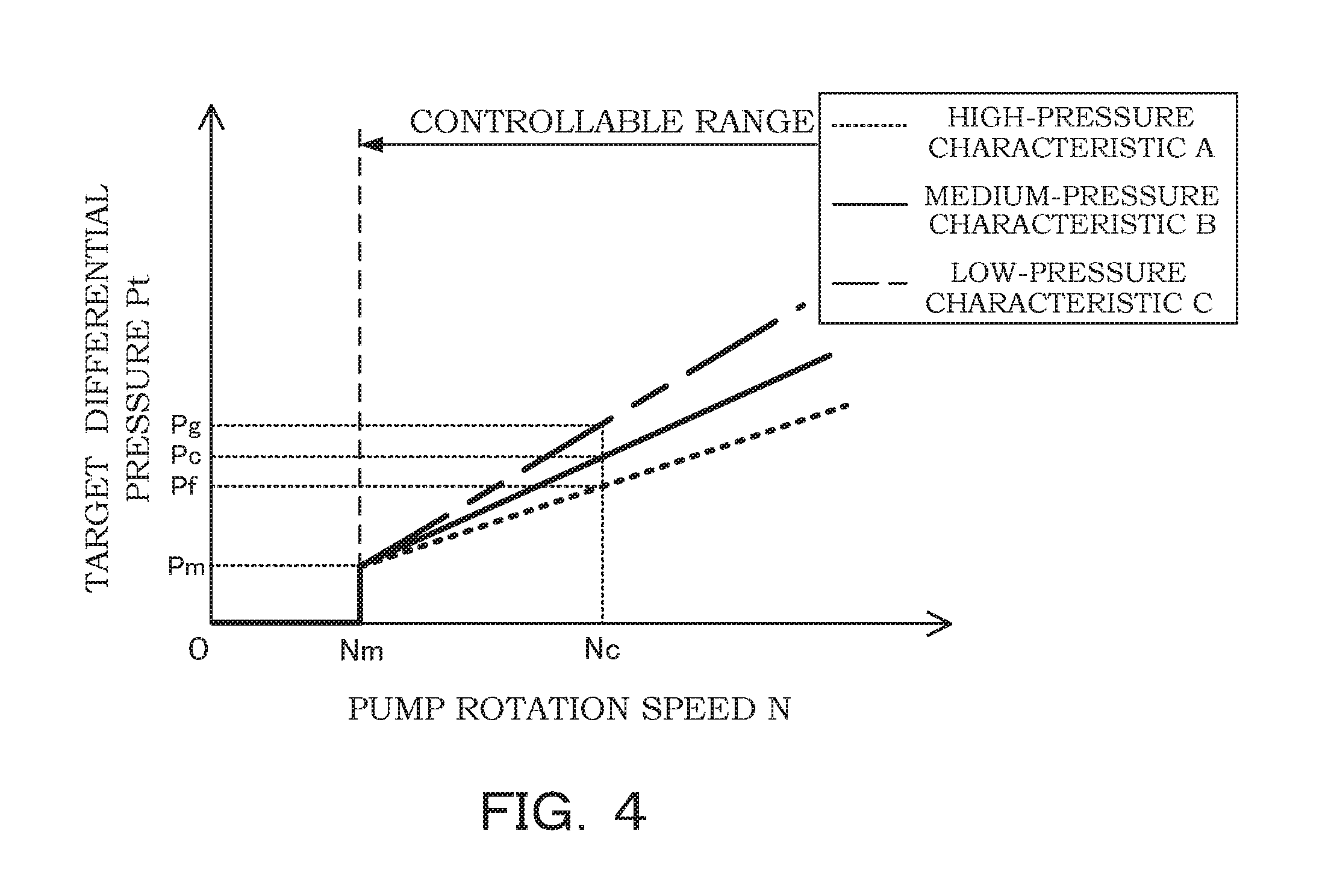
[0068] As shown in FIG. 4, with the pump device 200, in order to improve the precision of the control to keep the flow amount of the working oil supplied to the fluid pressure apparatus 50 constant (at the target flow amount), the characteristics of the pump rotation speed N and the target differential pressure Pt are changed on the basis of the pressure of the fluid pressure apparatus 50.
[0069] With the pump device 200, a signal for the pressure required by the fluid pressure apparatus 50 is input to the controller 60. As the signal for the pressure required by the fluid pressure apparatus 50 is input, the controller 60 selects, from the map shown in FIG. 4 stored in advance, the characteristics of the relationship between the pump rotation speed N and the target differential pressure Pt in accordance with the pressure required by the fluid pressure apparatus 50.
[0070] For example, while the control is performed at the pump rotation speed Nc with a medium-pressure characteristic B, when the pressure required by the fluid pressure apparatus 50 is increased, the controller 60 selects a high-pressure characteristic A shown in FIG. 4. In other words, the set pressure of the target differential pressure Pt is changed from the differential pressure Pc with the medium-pressure characteristic B to the differential pressure Pf with the high-pressure characteristic A. By doing so, the differential pressure Pd acting on the spool 21 of the flow control valve 2 is decreased. The pressure in the discharge channel 82 is increased when the pressure required by the fluid pressure apparatus 50 is increased, and the differential pressure between the pressure P1 in the first fluid pressure chamber 23 and the pressure in the tank 4 is increased. Correspondingly, the differential pressure Pd is decreased to reduce the degree of opening of the spool 21, thereby adjusting the returning-flow amount so as not to be changed. Thus, it is possible to keep the flow amount of the working oil supplied to the fluid pressure apparatus 50 constant (at the target flow amount).
[0071] In addition, while the control is performed at the pump rotation speed Nc with the medium-pressure characteristic B, when the pressure required by the fluid pressure apparatus 50 is decreased, the controller 60 selects a low-pressure characteristic C shown in FIG. 4. In other words, the target differential pressure Pt is changed from the differential pressure Pc with the medium-pressure characteristic B to a differential pressure Pg with the low-pressure characteristic C. By doing so, the differential pressure Pd acting on the spool 21 of the flow control valve 2 is increased. When the pressure required by the fluid pressure apparatus 50 is decreased, the pressure in the discharge channel 82 is decreased, and the differential pressure between the pressure P1 in the first fluid pressure chamber 23 and the pressure in the tank 4 is decreased. Correspondingly, the differential pressure Pd is increased to increase the degree of opening of the spool 21, thereby adjusting the returning-flow amount so as not to be changed. Thus, it is possible to keep the flow amount of the working oil supplied to the fluid pressure apparatus 50 constant (at the target flow amount).
[0072] In this way, even when the pressure required by the fluid pressure apparatus 50 is changed, in accordance with the pressure, the controller 60 selects the characteristic of the relationship between the pump rotation speed N and the target differential pressure Pt and performs the control on the basis of the selected characteristic such that the differential pressure Pd and the differential pressure Pe become the target differential pressure Pt, and thereby, it is possible to keep the flow amount of the working oil supplied to the fluid pressure apparatus 50 constant (at the target flow amount).
[0073] Although FIG. 4 shows stepwise characteristics like the high-pressure characteristic A, the medium-pressure characteristic B, and the low-pressure characteristic C, in practice, the characteristics are changed continuously between the high-pressure characteristic A and the low-pressure characteristic C. Of course, the characteristics may be changed in a stepwise manner. The medium-pressure characteristic B shown in FIG. 4 is only a conceptual illustration of a characteristic between the high-pressure characteristic A and the low-pressure characteristic C.
[0074] With the above-mentioned second embodiment, the following effects can be afforded.
[0075] With the pump device 200, the pressure required by the fluid pressure apparatus 50 is input to the controller 60, and the target differential pressure Pt is adjusted in accordance with the signal for this pressure. In other words, because the target differential pressure Pt is adjusted in accordance with the pressure required by the fluid pressure apparatus 50, it is possible to keep the flow amount of the working oil supplied to the fluid pressure apparatus 50 constant at a higher precision.
[0076] The above-mentioned second embodiment is configured such that the signal for the pressure required by the fluid pressure apparatus 50 is input to the controller 60. Instead of this configuration, a pressure detector may be provided in the discharge channel 82, and the signal from this pressure detector may be input to the controller 60. As the signal is input from the pressure detector, the controller 60 refers to the map shown in FIG. 4 and selects an appropriate characteristic for the relationship between the pump rotation speed N and the target differential pressure Pt in accordance with the pressure in the discharge channel 82 detected by the pressure detector. By doing so, it is possible to control the pump device 200, as in the case in which the signal for the pressure required by the fluid pressure apparatus 50 is input to the controller 60.
[0077] Configurations, operations, and effects of the embodiments according to the present invention will be collectively described below.
[0078] According to this embodiment, the pump device 100 includes the flow control valve 2 having the spool 21 that operates in accordance with the differential pressure Pd acting on both end portions thereof in such a manner that a part of the working fluid discharged from the pump 1 is returned to the suction channel 81 and the differential pressure adjusting device 3 that adjusts the differential pressure Pd acting on both end portions of the spool 21 to the target differential pressure Pt, wherein the differential pressure adjusting device 3 has the pressure regulating chamber 34 that is provided so as to face against the first-side end portion of the spool 31 and that communicates with the second fluid pressure chamber 24 and the pilot chamber 35 that is provided so as to face against the second-side end portion of the spool 31 and into which the pressure in the discharge channel 82 is guided. The pump device 100 is characterized in that the pressure P4 in the pressure regulating chamber 34 is adjusted such that the differential pressure Pe between the pressure P4 in the pressure regulating chamber 34 and the pressure P3 in the pilot chamber 35 becomes the target differential pressure Pt.
[0079] With this configuration, by adjusting the pressure P4 in the pressure regulating chamber 34 such that the differential pressure Pe between the pressure P4 in the pressure regulating chamber 34 and the pressure P3 in the pilot chamber 35 becomes the target differential pressure Pt, the differential pressure Pd acting on both end portions of the spool 21 of the flow control valve 2 is adjusted to the target differential pressure Pt. By doing so, because the working fluid discharged from the pump 1 is returned to the suction channel 81 through the flow control valve 2 in accordance with the target differential pressure Pt, it is possible to control the flow amount without providing a restrictor in the discharge channel 82. As described above, because a restrictor is not provided in the discharge channel 82, it is possible to reduce the torque for driving the pump 1.
[0080] In addition, in this embodiment, the pump device 100 is characterized in that the orifice 40 is further provided in the second communicating passage 84 communicating the discharge channel 82 and the second fluid pressure chamber 24.
[0081] With this configuration, by providing the orifice 40 in the second communicating passage 84, it is possible to adjust the pressure P2 in the second fluid pressure chamber 24 even when the flow amount of the working oil discharged through the differential pressure adjusting device 3 is small. Therefore, the size of the differential pressure adjusting device 3 can be reduced.
[0082] In addition, in this embodiment, the differential pressure adjusting device 3 is characterized in that the spring 33 that is accommodated in the pressure regulating chamber 34 in a compressed state and that biases the spool 31 in the valve-opening direction and the proportional solenoid 32 that is capable of changing the biasing force biasing the spool 31 in the valve-closing direction are further provided.
[0083] With this configuration, because the proportional solenoid 32 is used, it is possible to adjust the differential pressure Pd acting on both end portions of the spool 21 of the flow control valve 2 with high precision.
[0084] In addition, in this embodiment, it is characterized in that the target differential pressure Pt is adjusted in accordance with the pump rotation speed N of the pump 1.
[0085] With this configuration, even when the discharge flow amount is changed due to the change in the rotation speed N of the pump 1, because the target differential pressure Pt is adjusted in accordance with the rotation speed N of the pump 1, it is possible to control the flow amount of the working fluid supplied to the fluid pressure apparatus 50 to the target flow amount with high precision.
[0086] In addition, in this embodiment, it is characterized in that the target differential pressure Pt is adjusted in accordance with the pressure required by the fluid pressure apparatus 50.
[0087] With this configuration, even when the pressure required by the fluid pressure apparatus 50 is changed, because the target differential pressure Pt is adjusted in accordance with the changed pressure, it is possible to control the flow amount of the working fluid supplied to the fluid pressure apparatus 50 to the target flow amount with high precision.
[0088] Embodiments of this invention were described above, but the above embodiments are merely examples of applications of this invention, and the technical scope of this invention is not limited to the specific constitutions of the above embodiments.
[0089] In the above-mentioned embodiment, the target differential pressure Pt is changed by the pump rotation speed N of the pump 1. Instead of this configuration, a flow meter that detects a flow amount discharged by the pump 1 may be provided, and the target differential pressure Pt may be changed in accordance with the detected flow amount.
[0090] In addition, the pump device 100 may be configured such that a plurality of maps of the target flow amount shown in FIG. 2 or 4 may be stored in the controller 60 for each of different target flow amounts, and the controller 60 may appropriately select a map corresponding to the target flow amount in accordance with an instruction from the fluid pressure apparatus 50. In order to create a map with a different target flow amount, the position of the rotation speed Nm forming a break point of a graph should be shifted to the position of pump rotation speed corresponding to the target flow amount.
[0091] This application claims priority based on Japanese Patent Application No. 2014-187279 filed with the Japan Patent Office on Sep. 16, 2014, the entire contents of which are incorporated into this specification.
* * * * *
D00000
D00001
D00002
D00003
XML
uspto.report is an independent third-party trademark research tool that is not affiliated, endorsed, or sponsored by the United States Patent and Trademark Office (USPTO) or any other governmental organization. The information provided by uspto.report is based on publicly available data at the time of writing and is intended for informational purposes only.
While we strive to provide accurate and up-to-date information, we do not guarantee the accuracy, completeness, reliability, or suitability of the information displayed on this site. The use of this site is at your own risk. Any reliance you place on such information is therefore strictly at your own risk.
All official trademark data, including owner information, should be verified by visiting the official USPTO website at www.uspto.gov. This site is not intended to replace professional legal advice and should not be used as a substitute for consulting with a legal professional who is knowledgeable about trademark law.