Thermoelectric Element Of Vehicle Exhaust System
Lee; Seung Woo ; et al.
U.S. patent application number 14/930104 was filed with the patent office on 2016-12-29 for thermoelectric element of vehicle exhaust system. The applicant listed for this patent is Hyundai Motor Company. Invention is credited to Hong Kil Baek, Jin Woo Kwak, Han Saem Lee, Seung Woo Lee, Tae Won Lee, Su Jung Noh, Kyong Hwa Song.
| Application Number | 20160376971 14/930104 |
| Document ID | / |
| Family ID | 57537234 |
| Filed Date | 2016-12-29 |

| United States Patent Application | 20160376971 |
| Kind Code | A1 |
| Lee; Seung Woo ; et al. | December 29, 2016 |
THERMOELECTRIC ELEMENT OF VEHICLE EXHAUST SYSTEM
Abstract
A thermoelectric element of a vehicle exhaust system is provided, which achieves maximum generation efficiency without exceeding an endurance limit thereof. The thermoelectric element includes a thermoelectric module and a heat dissipation plate. Arrangement of the heat dissipation plate directly exposes one side to the exhaust system and the opposite side contacts the thermoelectric module. Furthermore, the thermoelectric element includes a cooling unit having interior cooling channels and disposed on the other side of the thermoelectric module.
| Inventors: | Lee; Seung Woo; (Seoul, KR) ; Song; Kyong Hwa; (Seoul, KR) ; Baek; Hong Kil; (Seoul, KR) ; Kwak; Jin Woo; (Gyeongsan, KR) ; Noh; Su Jung; (Seoul, KR) ; Lee; Tae Won; (Incheon, KR) ; Lee; Han Saem; (Seoul, KR) | ||||||||||
| Applicant: |
|
||||||||||
|---|---|---|---|---|---|---|---|---|---|---|---|
| Family ID: | 57537234 | ||||||||||
| Appl. No.: | 14/930104 | ||||||||||
| Filed: | November 2, 2015 |
| Current U.S. Class: | 60/320 |
| Current CPC Class: | Y02T 10/12 20130101; F01N 5/025 20130101; Y02T 10/16 20130101; H01L 35/30 20130101 |
| International Class: | F01N 5/02 20060101 F01N005/02 |
Foreign Application Data
| Date | Code | Application Number |
|---|---|---|
| Jun 26, 2015 | KR | 10-2015-0091356 |
Claims
1. A thermoelectric element of a vehicle exhaust system comprising: a thermoelectric module; a heat dissipation plate exposed to the exhaust system at a first side thereof while contacting a first side of the thermoelectric module at a second side; and a cooling unit disposed on a second side of the thermoelectric module and including a cooling channels within an interior.
2. The thermoelectric element according to claim 1, wherein the cooling unit includes: a cooling plate having a first side disposed at, on the second side of the thermoelectric module; and a cooling system disposed on a second side of the cooling plate and having the cooling channels disposed within the interior, to allow cooling water to flow therethrough.
3. The thermoelectric element according to claim 2, wherein the cooling plate and the cooling system are formed separately formed, and are coupled to one another.
4. The thermoelectric element according to claim 1, wherein the cooling unit has an integrated structure.
5. The thermoelectric element according to claim 1, wherein the heat dissipation plate is spaced apart from an adjacent surface of the exhaust system by a predetermined distance.
6. The thermoelectric element according to claim 1, wherein the heat dissipation plate obstructs a high temperature from the vehicle exhaust system from being directly applied to the thermoelectric element.
7. A vehicle having the thermoelectric element of claim 1.
Description
CROSS-REFERENCE TO RELATED APPLICATION
[0001] This application claims the priority benefit of Korean Patent Application No. 10-2015-0091356, filed on Jun. 26, 2015, in the Korean Intellectual Property Office, the disclosure of which is incorporated herein by reference.
BACKGROUND
[0002] 1. Field of the Invention
[0003] The present invention relates to a thermoelectric element installed within a vehicle exhaust system, and more particularly to a thermoelectric element capable of achieving maximum generation efficiency without exceeding an endurance limit.
[0004] 2. Description of the Related Art
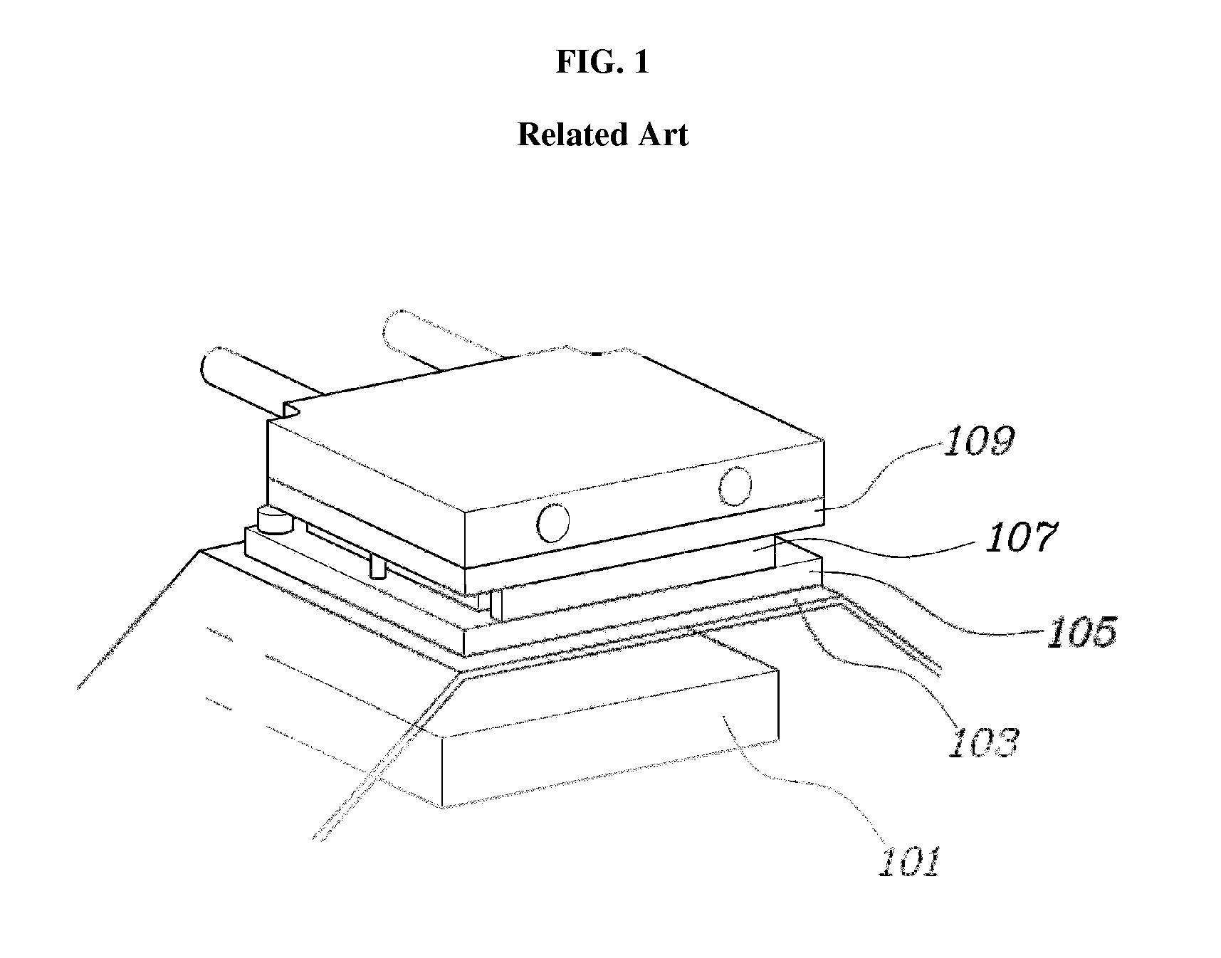
[0005] Generally, technology for mounting a thermoelectric element on a surface of a heat protector or a muffler installed at the side of an exhaust system within a vehicle converts exhaust heat into electrical energy for driving of electric components disposed within the vehicle. As shown in FIG. 1 a thermoelectric element is installed proximate to an exhaust system. Referring to FIG. 1, a heat shield plate 103 is installed separated from an exhaust system 101 to prevent engine parts from being damaged by exhaust heat. A heat dissipation plate 105 is disposed at a surface (e.g., adjacent) of the heat shield plate 103. A thermoelectric module 107 is positioned between the heat dissipation plate 105 and a cooling plate 109.
[0006] Typically, in such an arrangement of the thermoelectric element, exhaust heat absorbed by the heat dissipation plate is shielded by the heat shield plate and limits absorption of exhaust heat. For example, it may be difficult to achieve maximum generation efficiency since a heat dissipation temperature that enables the thermoelectric element may be difficult to maintain. Furthermore, a minimal temperature difference (e.g., .DELTA.T) between the heat dissipation plate and the cooling plate may reduce the generation amount.
[0007] For example, when .DELTA.T enabling the thermoelectric element to achieve maximum generation efficiency is within a range of about 180 to 230.degree. C., the temperature of heat dissipated from the heat dissipation plate (e.g., hot-side temperature) is in a range of about 150 to 200.degree. C. even though the temperature of exhaust gas is approximately as high as 700.degree. C. or greater. Accordingly, .DELTA.T is in a range of about 100 to 150.degree. C. and, as such, securing .DELTA.T capable of realizing maximum generation efficiency is limited. Thus, degradation of generation efficiency may occur.
[0008] Further, when the thermoelectric element is mounted directly (e.g. coupled to) on a surface of the exhaust system in order to remedy the above-mentioned problems, heat is directly applied to the thermoelectric element. In particular, the thermoelectric element may surpass a temperature exceeding a limit temperature, above which the thermoelectric element is no longer durable (e.g., functional). In this case, durability (e.g., functionality) of the thermoelectric element may be degraded.
[0009] The above matters disclosed in this section are merely for enhancement of understanding of the general background of the invention and should not be taken as an acknowledgement or any form of suggestion that the matters form the related art already known to a person skilled in the art.
SUMMARY
[0010] The present invention provides a thermoelectric element of a vehicle exhaust system, for achieving maximum generation efficiency without exceeding an endurance limit thereof. An exemplary embodiment provides a thermoelectric element of a vehicle exhaust system that may include a thermoelectric module, a heat dissipation plate that may be arranged to be directly exposed to the exhaust system at a first side (e.g., one) side and may contact (e.g., abut) a first side (e.g., one) side of the thermoelectric module at the second side (e.g., other) side of the heat dissipation plate. Further, a cooling unit may be disposed on the second (e.g., other) side of the thermoelectric module and may include cooling channels disposed on the interior thereof.
[0011] In some exemplary embodiments, the cooling unit may include a cooling plate coupled, at a first side, opposite to (e.g., on the other side of, opposing) the thermoelectric module, and a cooling system coupled to a second side (e.g., opposite side other side) of the cooling plate. The cooling channels may be disposed within the interior of the cooling plate, to allow cooling water to flow therethrough. In another exemplary embodiment, the cooling plate and the cooling system may be formed separately, and may be coupled to (e.g., interfaced with, assembled together) each other. The cooling unit may have an integrated structure. The heat dissipation plate may be separated (e.g., spaced apart) from a facing (e.g., opposing) surface of the exhaust system by a predetermined distance.
[0012] The present exemplary embodiment provides the following effects through the above-described configurations. For example, it may be possible to increase the temperature of heat dissipated from the heat dissipation plate to an allowable maximum temperature for the thermoelectric element which may be used, in place of the existing heat shield plate. The cooling unit may be spaced apart from the exhaust system and the heat dissipation plate may be disposed between the exhaust system and the cooling unit. Namely, the radiant heat of the exhaust system, typically lost by the heat shield plate in conventional systems may be reduced. Additionally, the temperature difference between the heat dissipation plate and the cooling plate may be increased and, the maximum generation efficiency of the thermoelectric element may be achieved. Furthermore, a reduction in manufacturing costs may be achieved by omitting the heat shield plate from the exhaust system.
[0013] Moreover, in some exemplary embodiments an amount of exhaust heat absorbed by the heat dissipation plate may be increased. For example, the thermoelectric element may be prevented (e.g., obstructed) from directly contacting the surface of the exhaust system. Accordingly, the thermoelectric element may be inhibited (e.g., prevented) from exceeding a high-temperature endurance limit and, the thermoelectric element may secure the desired high-temperature endurance.
BRIEF DESCRIPTION OF THE DRAWINGS
[0014] The above and other objects, features and other advantages of the present disclosure will be apparent from the following detailed description taken in conjunction with the accompanying drawings.
[0015] FIG. 1 is an exemplary view illustrating a thermoelectric element installed at a vehicle exhaust system in accordance with related art;
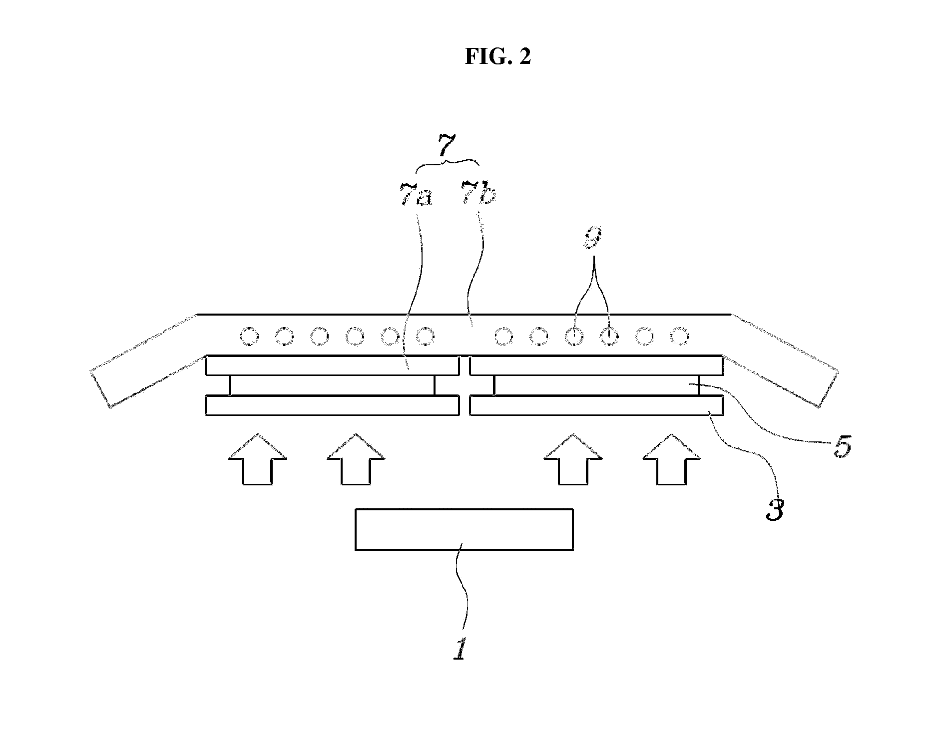
[0016] FIG. 2 is an exemplary view illustrating an arrangement of a thermoelectric element at a vehicle exhaust system in accordance with one exemplary embodiment of the present invention; and
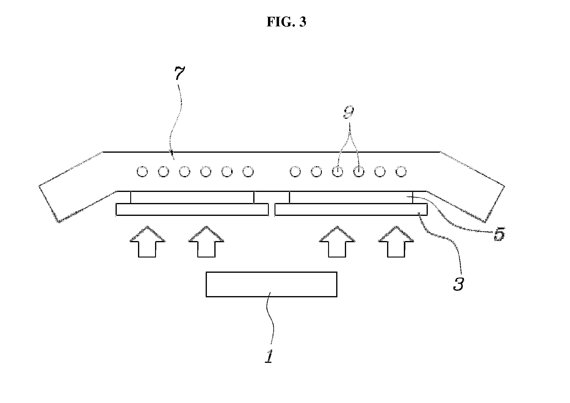
[0017] FIG. 3 is an exemplary view illustrating an arrangement of a thermoelectric element at a vehicle exhaust system in accordance with another exemplary embodiment of the present invention.
DETAILED DESCRIPTION
[0018] Advantages and features of the invention and methods of accomplishing the same may be understood more readily by reference to the following detailed descriptions of exemplary embodiments and the accompanying drawings. While the invention will be described in conjunction with exemplary embodiments, it will be understood that present description is not intended to limit the invention to those exemplary embodiments. On the contrary, the invention is intended to cover not only the exemplary embodiments, but also various alternatives, modifications, equivalents and other embodiments, which may be included within the spirit and scope of the invention as defined by the appended claims.
[0019] It is understood that the term "vehicle" or "vehicular" or other similar term as used herein is inclusive of motor vehicles in general such as passenger automobiles including sports utility vehicles (SUV), buses, trucks, various commercial vehicles, watercraft including a variety of boats and ships, aircraft, and the like, and includes hybrid vehicles, electric vehicles, plug-in hybrid electric vehicles, hydrogen-powered vehicles and other alternative fuel vehicles (e.g. fuels derived from resources other than petroleum). As referred to herein, a hybrid vehicle is a vehicle that has two or more sources of power, for example both gasoline-powered and electric-powered vehicles.
[0020] The terminology used herein is for the purpose of describing particular embodiments only and is not intended to be limiting of the invention. As used herein, the singular forms "a", "an" and "the" are intended to include the plural forms as well, unless the context clearly indicates otherwise. It will be further understood that the terms "comprises" and/or "comprising," when used in this specification, specify the presence of stated features, integers, steps, operations, elements, and/or components, but do not preclude the presence or addition of one or more other features, integers, steps, operations, elements, components, and/or groups thereof. As used herein, the term "and/or" includes any and all combinations of one or more of the associated listed items. For example, in order to make the description of the present invention clear, unrelated parts are not shown and, the thicknesses of layers and regions are exaggerated for clarity. Further, when it is stated that a layer is "on" another layer or substrate, the layer may be directly on another layer or substrate or a third layer may be disposed therebetween.
[0021] Unless specifically stated or obvious from context, as used herein, the term "about" is understood as within a range of normal tolerance in the art, for example within 2 standard deviations of the mean. "About" can be understood as within 10%, 9%, 8%, 7%, 6%, 5%, 4%, 3%, 2%, 1%, 0.5%, 0.1%, 0.05%, or 0.01% of the stated value. Unless otherwise clear from the context, all numerical values provided herein are modified by the term "about."
[0022] Reference will now be made in detail to the exemplary embodiments of the present invention, examples of which are illustrated in the accompanying drawings. Wherever possible, the same reference numbers will be used throughout the drawings to refer to the same or like parts.
[0023] Referring to FIGS. 2 and 3, a thermoelectric element of a vehicle exhaust system according to an exemplary embodiment is illustrated. The thermoelectric element may include a heat dissipation plate 3 and a cooling unit 7. Hereinafter, the thermoelectric element of the exemplary embodiment will be described in detail with reference to FIGS. 2 and 3. The heat dissipation plate 3 may be arranged to directly face (e.g., positioned opposite to) an exhaust system 1 at a first side (e.g., one side) thereof. A thermoelectric module 5 may be disposed, at a second side (e.g., one side) of the exhaust system, on the second side (e.g., opposite side) of the heat dissipation plate 3. In particular, the exhaust system 1 may be a part (e.g., a portion) of the vehicle exhaust system that may emit high exhaust heat, for example, an exhaust manifold a muffler or the like.
[0024] For example, the thermoelectric module 5 may be disposed, at the other side (e.g., an opposite side) of the exhaust system, on the other side of the heat dissipation plate 3 and the surfaces may contact (e.g., interface with one another). The exhaust heat may be absorbed by the heat dissipation plate 3 and may be transferred (e.g., transmitted) to the thermoelectric module 5. In particular, the heat dissipation plate 3 may be separated (e.g., spaced apart) from an opposing surface (e.g., a facing surface) of the exhaust system 1 by a predetermined distance. For example, it may be possible to prevent (e.g., obstruct) high temperature from the exhaust system 1 from being directly applied to the thermoelectric element. Accordingly, the thermoelectric element may be prevented from exceeding a high-temperature endurance limit. Further, the cooling unit 7 may be disposed on the opposite side (e.g., other side) of the thermoelectric module 5. Cooling channels 9 may be disposed within the interior of the thermoelectric module 5. The cooling unit 7 may include a cooling plate 7a and a cooling system 7b.
[0025] Referring to FIG. 2, the cooling plate 7a may be disposed, at a first side (e.g., one side) thereof, on the opposite side (e.g., other side) of the thermoelectric module 5 in a surface contact manner. The cooling system 7b may be disposed on the opposite side (e.g., other side) of the cooling plate 7a and the surfaces may contact (e.g., interface with one another, coupled to one another) one another. A plurality of cooling channels 9 may be installed within the interior of the cooling system 7b, to facilitate cooling water to flow through the cooling system 7b. Additionally, the cooling system 7b may have a block shape or the like. In other words, the cooling plate 7a and cooling system 7b may be formed separately formed and, as such, may be assembled to allow the surfaces to contact (e.g., interface, coupled to) one another.
[0026] In particular, the cooling system 7b may be formed to have a greater size than the size of the heat dissipation plate 3 and thermoelectric module 5. For example, the cooling system 7b may include lateral and longitudinal dimensions that may cover one surface of the exhaust system 1 that faces the cooling system 7b and, may function as the heat shield plate. Additionally, it may be possible to avoid damage to components proximate to the exhaust system 1 caused by exhaust heat, through the cooling system 7b.
[0027] Alternatively, the cooling unit 7 of the exemplary embodiments may include an integrated structure disposed on the opposite (e.g., other) side of the thermoelectric module 5. Referring to FIG. 3, the cooling unit 7 may have a structure in which the cooling plate 7a and cooling system 7b may be integrated. For example, the integrated structure may perform both the function of the cooling plate 7a and the function of the cooling system 7b. In other words, a plurality of cooling channels 9, through which cooling water flows, may be installed within the interior of the cooling unit 7. In particular, the cooling unit 7 may have a greater size than those of the heat dissipation plate 3 and thermoelectric module 5. For example, the cooling unit 7 may include lateral and longitudinal dimensions that may cover one surface of the exhaust system 1 adjacent to (e.g., facing) the cooling unit 7 and, may function as the heat shield plate. Additionally, it may be possible to prevent damage to components proximate to the exhaust system 1 caused by exhaust heat, via the cooling unit 7.
[0028] In some exemplary embodiments, the temperature of heat dissipated from the heat dissipation plate 3 may be increased to an allowable maximum temperature for the thermoelectric element. For example, in place of the existing heat shield plate, the cooling unit 7 may be separated from (e.g., spaced apart) from the exhaust system 1 when the heat dissipation plate 3 is disposed between the exhaust system 1 and the cooling unit 7. Accordingly, the radiant heat of the exhaust system 1, typically lost by the heat shield plate in conventional cases may be reduced. Additionally, the temperature difference between the heat dissipation plate 3 and the cooling plate 7a may be increased and the maximum generation efficiency of the thermoelectric element may be achieved. Accordingly, a reduction in manufacturing costs may be achieved by removing the heat shield plate from the exhaust system 1.
[0029] Furthermore, an amount of exhaust heat absorbed by the heat dissipation plate 3 may be increased when the thermoelectric element may be prevented from directly contacting the surface of the exhaust system 1. Accordingly, the thermoelectric element may be prevented from exceeding a high-temperature endurance limit thereof and, as such, the thermoelectric element may achieve the desired high-temperature endurance.
[0030] While this invention has been described in connection with what is presently considered to be exemplary embodiments on the contrary, it is intended to cover various modifications and equivalent arrangements without departing from the scope and spirit of the invention as disclosed in the accompanying claims. In addition, it is to be considered that all of these modifications and alterations fall within the scope of the present invention
* * * * *
D00000
D00001
D00002
D00003
XML
uspto.report is an independent third-party trademark research tool that is not affiliated, endorsed, or sponsored by the United States Patent and Trademark Office (USPTO) or any other governmental organization. The information provided by uspto.report is based on publicly available data at the time of writing and is intended for informational purposes only.
While we strive to provide accurate and up-to-date information, we do not guarantee the accuracy, completeness, reliability, or suitability of the information displayed on this site. The use of this site is at your own risk. Any reliance you place on such information is therefore strictly at your own risk.
All official trademark data, including owner information, should be verified by visiting the official USPTO website at www.uspto.gov. This site is not intended to replace professional legal advice and should not be used as a substitute for consulting with a legal professional who is knowledgeable about trademark law.