Interment System With Underground Container
Eickhof; Paul M. ; et al.
U.S. patent application number 15/192791 was filed with the patent office on 2016-12-29 for interment system with underground container. The applicant listed for this patent is Eickhof Columbaria, Inc.. Invention is credited to Paul M. Eickhof, Stephen Noyes.
| Application Number | 20160376810 15/192791 |
| Document ID | / |
| Family ID | 57601900 |
| Filed Date | 2016-12-29 |


View All Diagrams
| United States Patent Application | 20160376810 |
| Kind Code | A1 |
| Eickhof; Paul M. ; et al. | December 29, 2016 |
INTERMENT SYSTEM WITH UNDERGROUND CONTAINER
Abstract
A system for interring cremated remains includes a first structure above ground housing multiple storage niches. A repository underground includes a long-lasting waterproof storage compartment. A delivery chute leads from an access niche to the storage compartment. A flexible container holds individual cremated remains and is configured for inserting into the first niche and passing through the chute to the storage compartment.
| Inventors: | Eickhof; Paul M.; (Crookston, MN) ; Noyes; Stephen; (Brooklyn, NY) | ||||||||||
| Applicant: |
|
||||||||||
|---|---|---|---|---|---|---|---|---|---|---|---|
| Family ID: | 57601900 | ||||||||||
| Appl. No.: | 15/192791 | ||||||||||
| Filed: | June 24, 2016 |
Related U.S. Patent Documents
| Application Number | Filing Date | Patent Number | ||
|---|---|---|---|---|
| 62184733 | Jun 25, 2015 | |||
| Current U.S. Class: | 52/133 |
| Current CPC Class: | E04H 13/006 20130101; E04H 13/008 20130101; E04H 13/003 20130101; E04H 13/001 20130101 |
| International Class: | E04H 13/00 20060101 E04H013/00 |
Claims
1. An interment system, comprising: a first structure above ground comprising a plurality of storage niches; a second structure comprising an underground repository; and a delivery system leading from an access niche of the plurality of niches to the underground repository.
2. The interment system according to claim 1, wherein the repository comprises a vault with a waterproof vessel.
3. The interment system according to claim 1, wherein the delivery system comprises a chute extending through at least a second niche of the plurality of niches.
4. The interment system according to claim 3, wherein the delivery system comprises an opening in the access niche.
5. The interment system according to claim 1, wherein the first structure comprises an obelisk.
6. The interment system according to claim 1, further comprising a distributor for dispersing containers of remains in the underground repository.
7. The interment system according to claim 6, wherein the distributor comprises a rounded upper surface positioned below the delivery system.
8. The interment system according to claim 1, further comprising a plurality of pavers dispersed on the ground around the first structure.
9. A system for interring cremated remains, comprising: a first structure above ground comprising a plurality of storage niches; a second structure underground comprising a waterproof storage compartment; a delivery system leading from an access niche of the plurality of niches to the storage compartment; and a container holding individual cremated remains configured for inserting into the access niche and passing through the delivery system to the storage compartment.
10. A system according to claim 9, wherein the container comprises a sealed flexible bag having an impermeable inner liner.
11. The interment system according to claim 9, further comprising a distributor for dispersing the containers holding remains in the underground repository.
12. An interment system, comprising: a first structure above ground comprising a plurality of storage niches; a second structure associated with the first structure, the second structure comprising an underground repository; and a delivery system leading from above ground to the underground repository.
13. The interment system according to claim 12, wherein the first structure comprises a plurality of identifiers associated with remains interred in the underground repository.
14. The interment system according to claim 13, wherein the first structure comprises an obelisk.
15. The interment system according to claim 12, wherein the first structure comprises an obelisk.
16. The interment system according to claim 12, comprising a plurality of the first structures associate with the second structure.
17. The interment system according to claim 12, wherein the repository comprises a vault having a waterproof vessel.
18. An interment system, comprising: a first structure above ground comprising an access section and a plurality of identifiers; a second structure comprising an underground repository; and a delivery system leading from the first structure to the underground repository.
19. The interment system according to claim 18, wherein the first structure comprises an obelisk.
20. The interment system according to claim 18, wherein the access section comprises an opening and removable cover.
21. The interment system according to claim 18, further comprising a container holding individual remains configured for being inserted into the opening and passing through the delivery system to the underground repository.
Description
BACKGROUND OF THE INVENTION
[0001] Field of the Invention
[0002] The present invention is directed to an interment system including an arrangement for delivering remains to an underground repository.
[0003] Description of the Prior Art
[0004] As cost and space issues have led to fewer conventional burials and to a greater number of people choosing cremation, different systems have been developed for handling remains in a dignified and respectful manner. Above ground columbarium systems have multiple niches that are able to store urns in a dignified secure manner and provide durability for withstanding exposure to weather for the long times required. However, even costs of a columbarium having smaller storage spaces then traditional burials or crypts as well as the desire to actually be buried below ground, may lead to others seeking different options. An ossuarium provides for interring multiple separate cremated individual remains below ground in a single repository. Although an ossuarium may use a single repository, it is still desirable to have a record of the individuals whose remains are interred to indicate their final resting place. Therefore, it is desirable to provide an above ground marker such as a plaque, paver or lasting weatherproof indication of those interred in the ossuarium. Such an above ground marker may also function to store additional remains.
[0005] It can also be appreciated that delivery of the remains to a below ground vault should provide for a respectful and dignified delivery of the remains into the vault. Such a delivery system should ensure that the remains cannot get caught to prevent clogs and should provide for security as well as being weather proof.
[0006] Traditional urns may not be suitable for being dropped through a delivery system and landing in a vault with other remains. Traditional urns may create generate noise when landing in the repository and striking other urns. Moreover, there may also be a risk of the urn cracking or breaking open and/or releasing the remains. Therefore, the discrete storage of each individual's remains should be configured for delivery to and interment in a below ground vault.
[0007] It is therefore seen that an improved interment system is needed that provides for delivery and permanent storage of cremated remains in a dignified and reverent manner. Such a storage system should provide for durable weather proof storage and also a safe and reliable delivery system to the underground repository. The system should also provide a proper record of the deceased who have been interred. Moreover, storage devices for the cremated remains of each individual should also be suitable for delivery through a system to an underground vault. The present invention addresses these as well as other problems associated with interment systems.
SUMMARY OF THE INVENTION
[0008] An interment system includes structures for storing cremated remains both above ground and below ground. A first structure such as an obelisk above ground includes storage niches that are accessed through removable panels. Each of the niches may store one or more urns or other suitable containers. In addition, a second structure below ground is a repository for other cremated remains. Access to the second structure is attained through an access niche in the first structure above ground. A chute leads from the access niche to the underground repository.
[0009] The underground repository is a durable waterproof container that will not deteriorate and provides for permanently storing multiple containers, each holding an individual's cremated remains. The underground repository may include a distributor to disperse the containers about the container vessel.
[0010] The system is particularly suited for use with flexible type urns such as impermeable bags that may be sealed to contain an individual's remains. The flexible containers may be deposited in a dignified manner through the access niche and are received in the underground repository. The stone facing of the obelisk provides for a decorative and dignified interment above ground and options to accommodate different preferences and different costs. The obelisk may take on several configurations and sizes and may include a widened lower section with niches and an obelisk section having niches.
[0011] In other embodiments, the remains may be deposited through a dedicated access and delivery structure without above ground storage. Such a structure includes a secure access point for depositing the remains in a dignified manner. A delivery chute leads to the underground repository. It also foreseen that the system may include additional elements that provide for inscriptions or otherwise recording the names of the interred. It is foreseen that walls, pavers or other elements may be used alone or in various combinations to indicate the names of the interred.
[0012] These features of novelty and various other advantages that characterize the invention are pointed out with particularity in the claims annexed hereto and forming a part hereof. However, for a better understanding of the invention, its advantages, and the objects obtained by its use, reference should be made to the drawings that form a further part hereof, and to the accompanying descriptive matter, in which there is illustrated and described a preferred embodiment of the invention.
BRIEF DESCRIPTION OF THE DRAWINGS
[0013] FIG. 1 is a front elevational view of a first embodiment of an obelisk with a delivery system to a below ground repository according to the principles of the present invention;
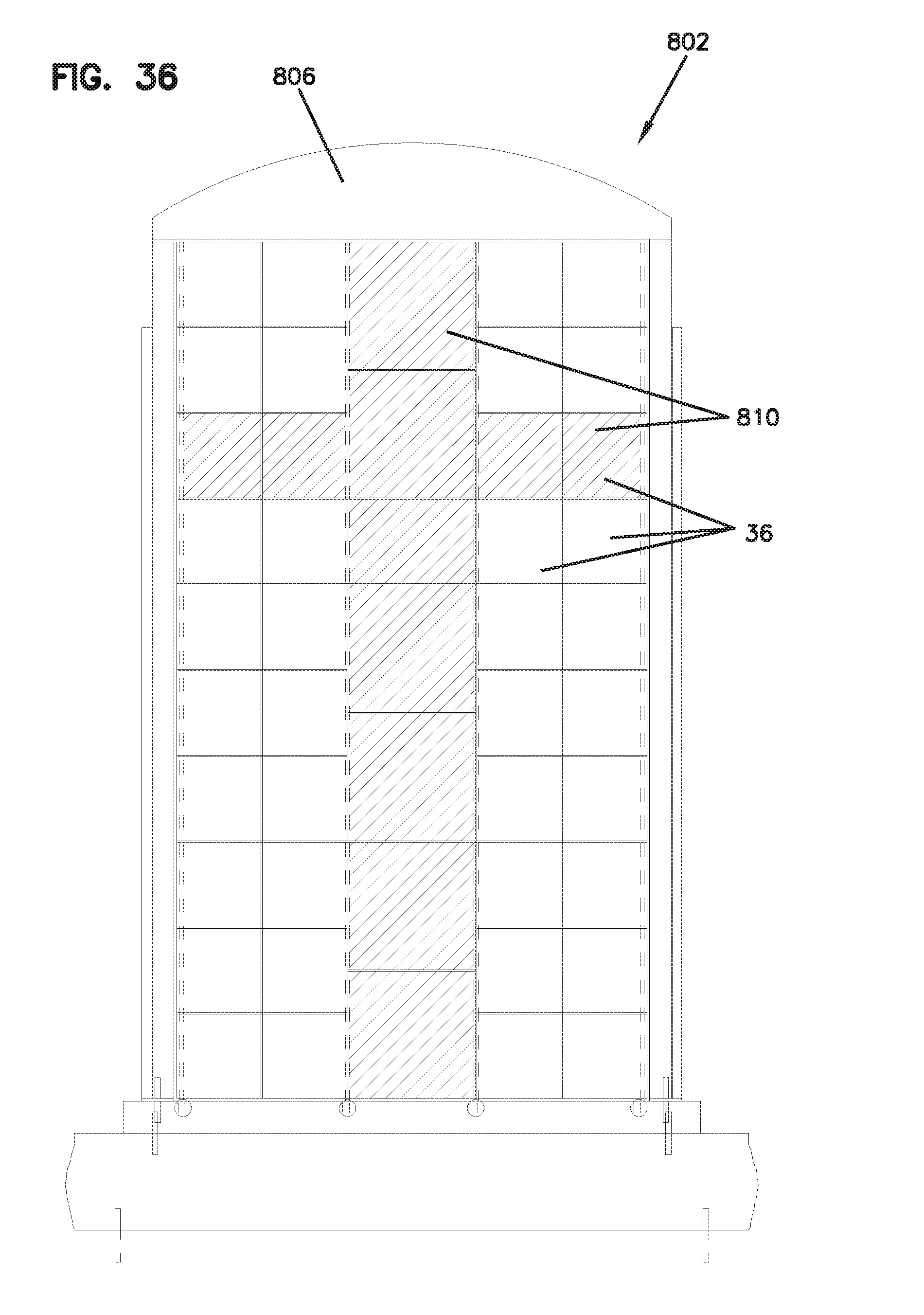
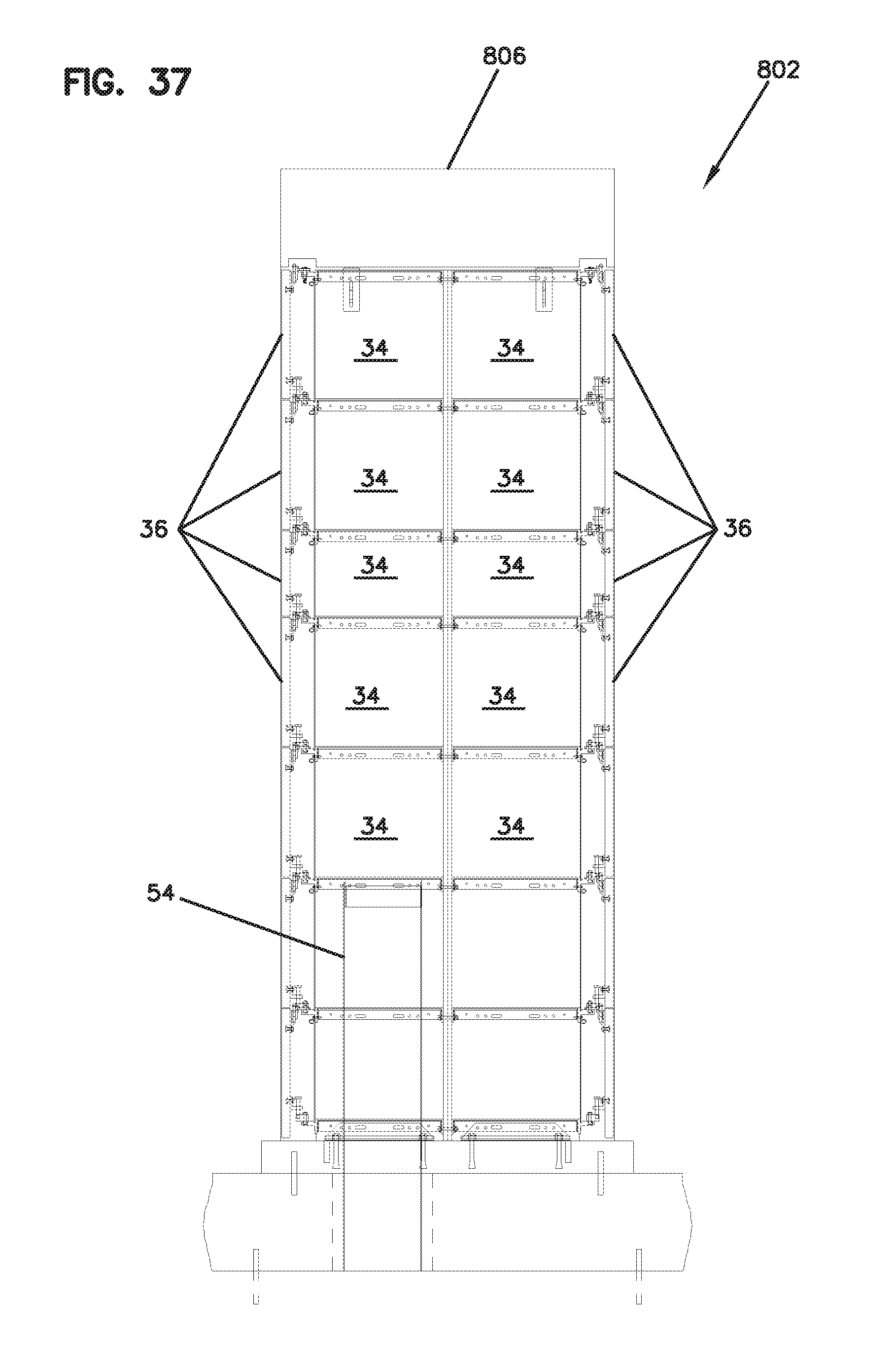
[0014] FIG. 2 is a side sectional view of the system shown in FIG. 1;
[0015] FIG. 3 is a side sectional view of the obelisk and delivery chute for the system shown in FIG. 1;
[0016] FIG. 4 is a side view of the obelisk with the facing panels removed for the system shown in FIG. 1;
[0017] FIG. 5 is a top sectional view through an access niche and chute for the system shown in FIG. 1;
[0018] FIG. 6 is a top plan view of the support beam for the underground repository for the system shown in FIG. 1;
[0019] FIG. 7 is a bottom plan view of the vessel and supports for the underground repository for the system shown in FIG. 1;
[0020] FIG. 8 is a side sectional view of the underground vessel and delivery chute for the system shown in FIG. 1;
[0021] FIG. 9 is a top plan view of the delivery chute and vessel shown in FIG. 8;
[0022] FIG. 10 is a front view of a flexible urn for the storage of remains for the ossuary shown in FIG. 1;
[0023] FIG. 11 is a sectional view of the flexible urn taken along line 11-11 in FIG. 10;
[0024] FIG. 12 is a side sectional view of a second embodiment of an ossuary and delivery system according to the principles of the present invention;
[0025] FIG. 13 is a top plan view of marker pavers for use with the system shown in FIG. 12;
[0026] FIG. 14 is a side sectional view of a third embodiment of an ossuary and delivery system according to the principles of the present invention.
[0027] FIG. 15 is a side elevational view with portion shown in section of a fourth embodiment of an ossuary and delivery system according to the principles of the present invention;
[0028] FIG. 16 is a side elevational view of the above ground portion of the ossuary and delivery system shown in FIG. 15;
[0029] FIG. 17 is a side sectional view of the above ground portion of the ossuary and delivery system shown in FIG. 15;
[0030] FIG. 18 is a sectional plan view of the lower section of the above ground portion of the ossuary and delivery system shown in FIG. 15;
[0031] FIG. 19 is a side elevational view with portion shown in section of a fifth embodiment of an ossuary and delivery system according to the principles of the present invention;
[0032] FIG. 20 is a side elevational view of the above ground portion of the ossuary and delivery system shown in FIG. 19;
[0033] FIG. 21 is a side sectional view of the above ground portion of the ossuary and delivery system shown in FIG. 19;
[0034] FIG. 22 is a sectional plan view of the lower section of the above ground portion of the ossuary and delivery system shown in FIG. 19;
[0035] FIG. 23 is a side elevational view with portion shown in section of a sixth embodiment of an ossuary and delivery system according to the principles of the present invention;
[0036] FIG. 24 is a side elevational view of the above ground portion of the ossuary and delivery system shown in FIG. 23;
[0037] FIG. 25 is a side sectional view of the above ground portion of the ossuary and delivery system shown in FIG. 23;
[0038] FIG. 26 is a sectional plan view of the lower section of the above ground portion of the ossuary and delivery system shown in FIG. 23;
[0039] FIG. 27 is a side elevational view with portion shown in section of a seventh embodiment of an ossuary and delivery system according to the principles of the present invention;
[0040] FIG. 28 is a side elevational view of the above ground portion of the ossuary and delivery system shown in FIG. 27;
[0041] FIG. 29 is a side sectional view of the above ground portion of the ossuary and delivery system shown in FIG. 27;
[0042] FIG. 30 is a sectional plan view of the lower section of the above ground portion of the ossuary and delivery system shown in FIG. 27;
[0043] FIG. 31 is a side elevational view with portion shown in section of an eighth embodiment of an ossuary and delivery system according to the principles of the present invention;
[0044] FIG. 32 is a side elevational view of the above ground portion of the ossuary and delivery system shown in FIG. 31;
[0045] FIG. 33 is a side sectional view of the above ground portion of the ossuary and delivery system shown in FIG. 31;
[0046] FIG. 34 is a sectional plan view of the lower section of the above ground portion of the ossuary and delivery system shown in FIG. 31;
[0047] FIG. 35 is a side elevational view with portion shown in section of a ninth embodiment of an ossuary and delivery system according to the principles of the present invention;
[0048] FIG. 36 is a side elevational view of the above ground portion of the ossuary and delivery system shown in FIG. 35;
[0049] FIG. 37 is a side sectional view of the above ground portion of the ossuary and delivery system shown in FIG. 35;
[0050] FIG. 38 is an alternate side sectional view of the above ground portion of the ossuary and delivery system shown in FIG. 35; and
[0051] FIG. 39 is a sectional plan view of the lower section of the above ground portion of the ossuary and delivery system shown in FIG. 35.
DETAILED DESCRIPTION OF THE PREFERRED EMBODIMENT
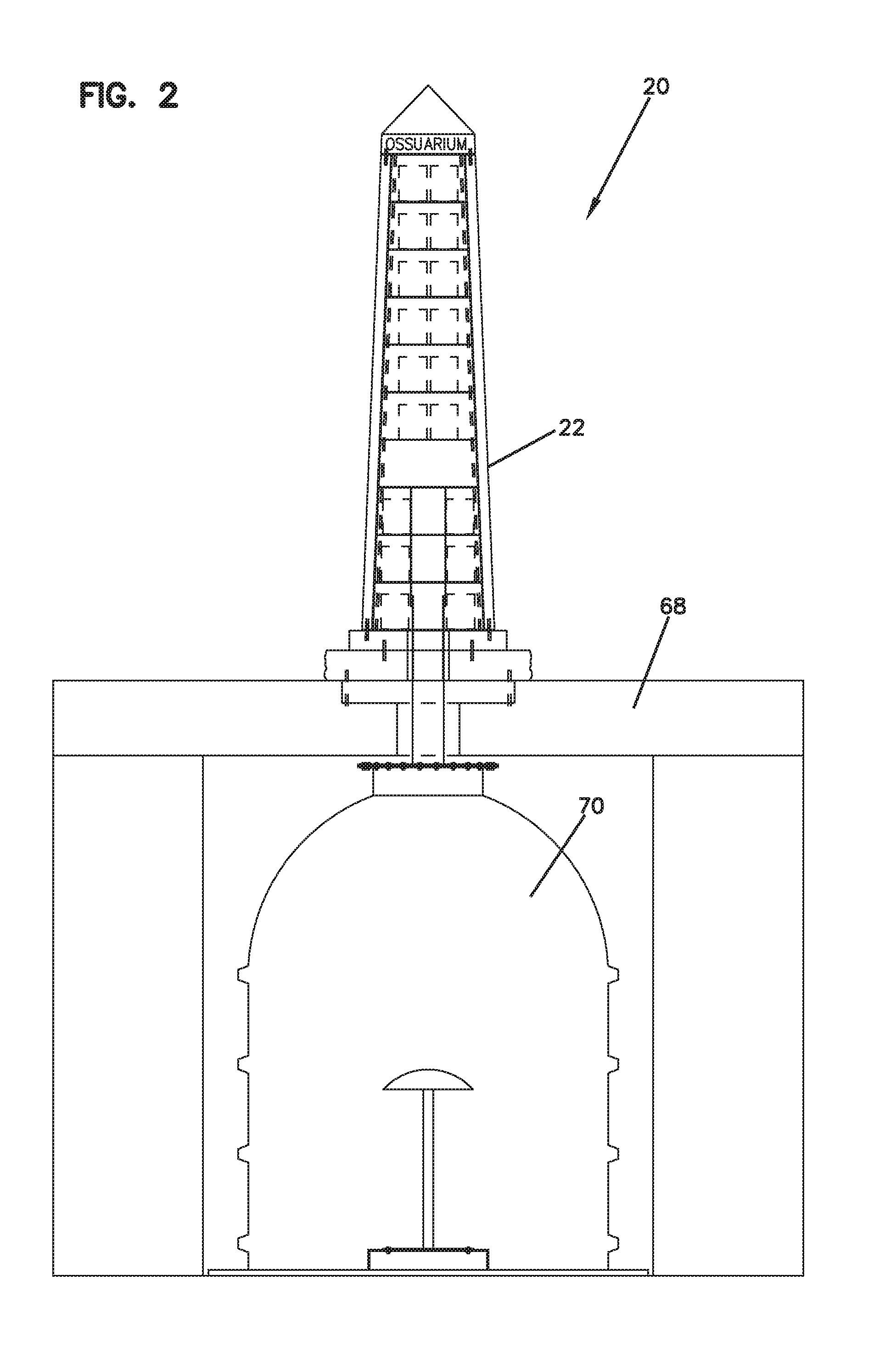
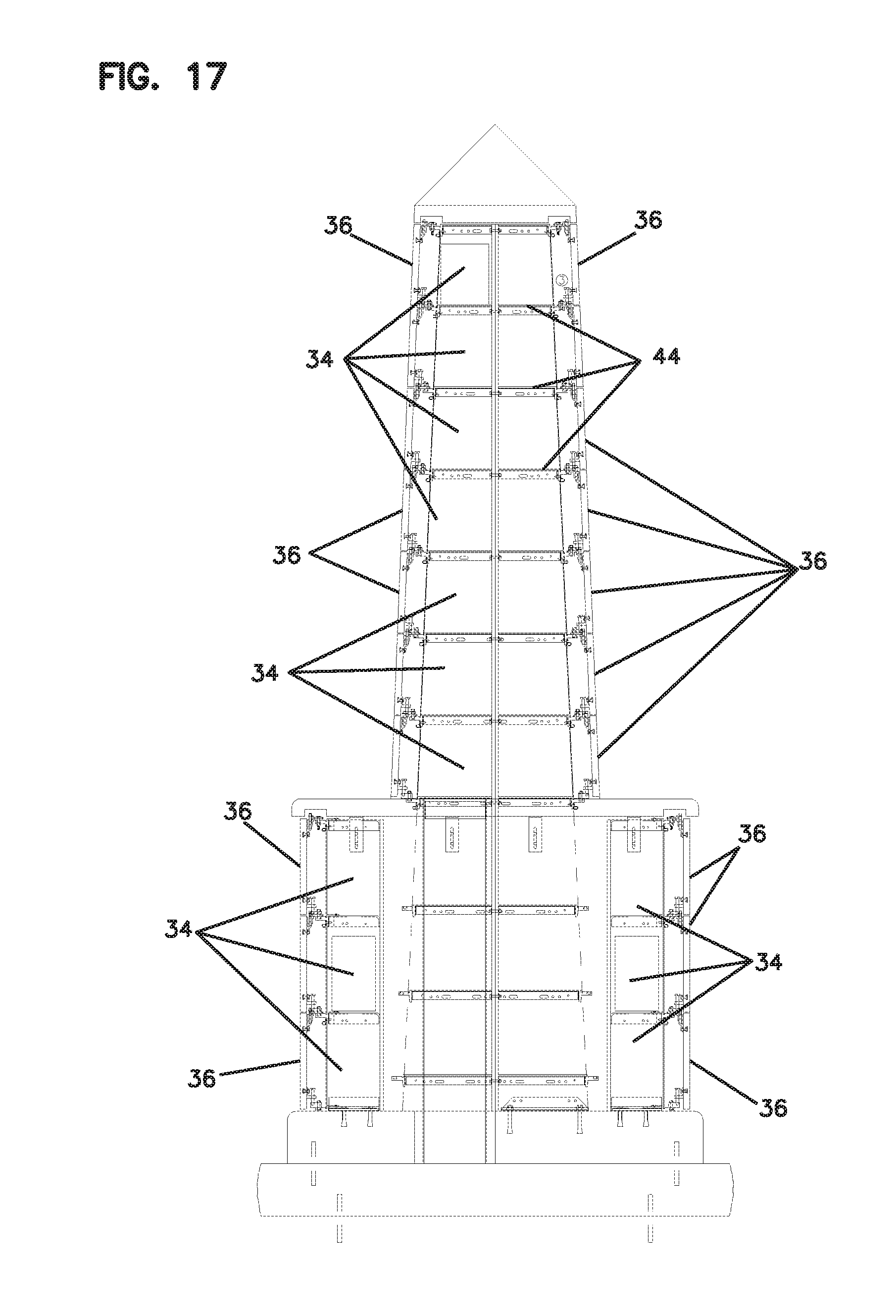
[0052] Referring to the drawings and in particular to FIGS. 1 and 2, there is shown a first embodiment of an interment system (20) according to the principles of the present invention. The interment system (20) is configured for interring cremated remains in a dignified manner. The system (20) provides for interment both above and below ground. In one embodiment, the system (20) generally includes an above ground obelisk type columbarium (22), a delivery system (24) and an underground repository (26). The obelisk structure (22) generally includes outer facing panels (36) with at least some of the facing panels (36) being removable to access interiors of niches (34) for storing remains and urns or other appropriate containers. The facing panels (36) and other exterior of the obelisk (22) may be made of granite, marble or other commonly used decorative stone materials and for some installations may be wood, bronze or other decorative facing. Inscriptions may be engraved or otherwise formed in the facing to designate remains of those who have been interred. The obelisk (22) generally mounts on a base (48) and is secured in the ground.
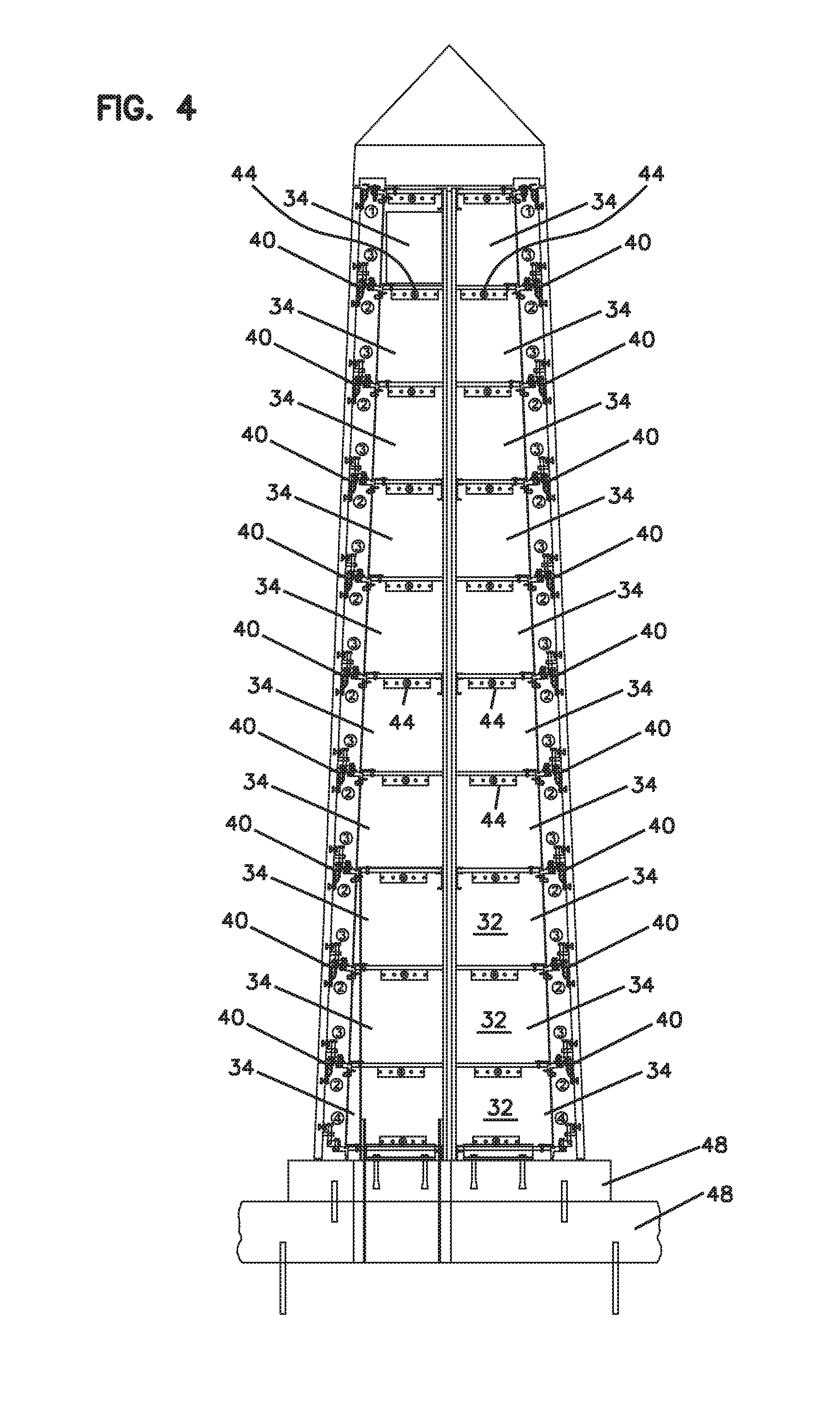
[0053] As shown in FIGS. 3 and 4, the obelisk (22) forms niches (34) separated by a framework (32) having walls (42) and floor/ceiling elements (44). In the embodiment shown in FIGS. 1-4, the obelisk (22) forms 19 niches. However, embodiments with a different number of niches are possible. The niches (34) generally store one or more urns (58) in a conventional manner as done with other columbaria. As shown in FIG. 3, the obelisk (22) also includes an access niche (50). The access niche (50) is configured to provide access to the underground repository (26). The access niche (50) includes an opening (52) to access a chute (54) leading to the repository (26). It can be appreciated that the chute (54) leads from the opening (52) from about one inch below the floor (44) of the access niche (50) and passes down through other niches below the access niche (50). It can be appreciated that the niches (32) below the access niche (50) have less space to store remains than the niches (34) above the access niche (50). Therefore, generally a maximum of two urns (58) may be stored in the niches (32) below the access niche (50). The chute (54) extends through the base (48). The chute (54) may be a single element or may be a series of aligned elements, but is configured to be straight and have a smooth inner surface so that remains deposited through the opening (52) do not catch or become caught anywhere along the chute (54).
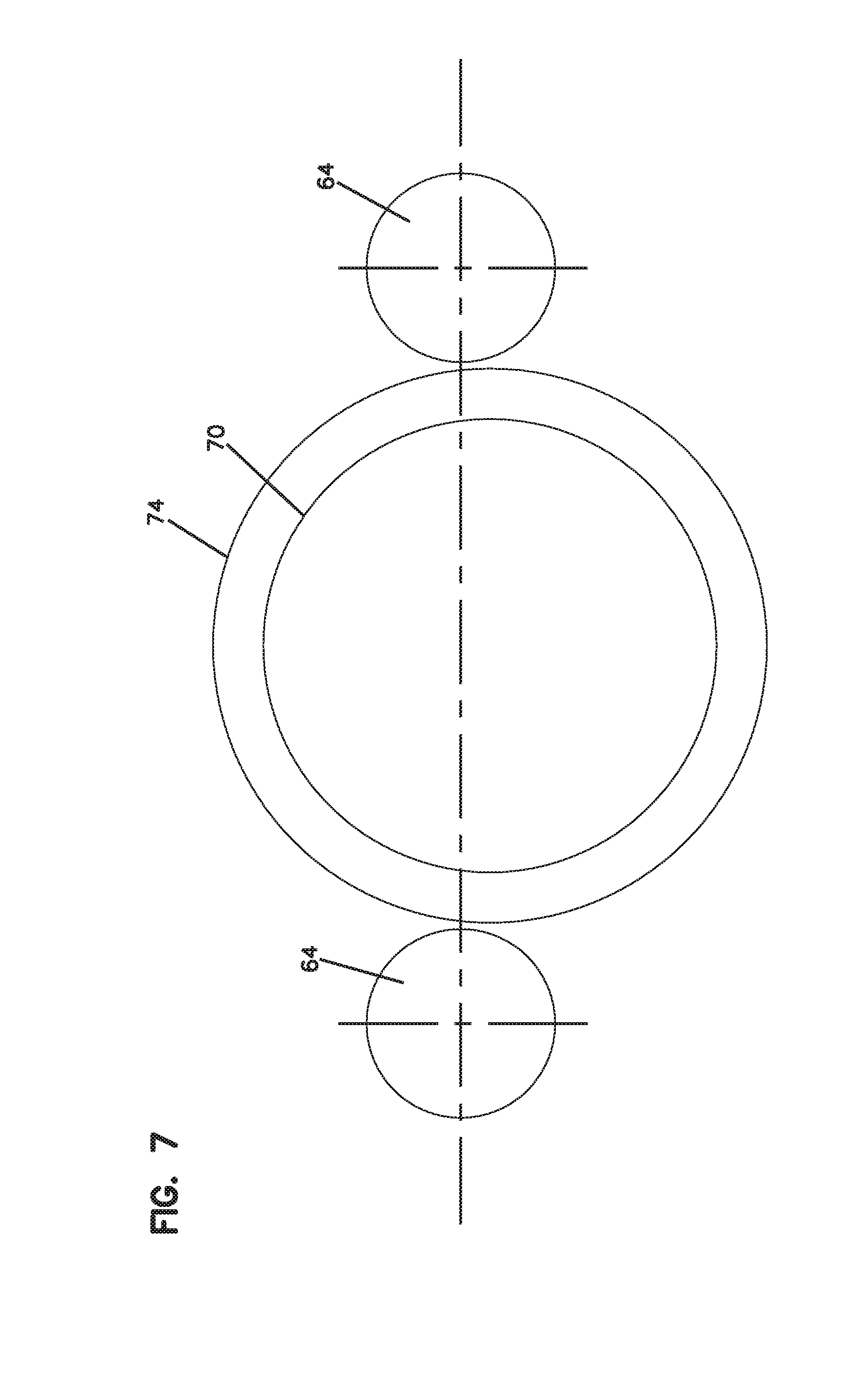
[0054] Referring now to FIGS. 6 and 7, the underground repository structure (26) includes a supporting framework. The repository structure (26) includes a beam (68) supported on posts (64). The posts (64) may be poured concrete, block-type pillars or other well-known structures providing support for the beam. The posts (64) may have a round, square, rectangular or any other conventional cross-section. The beam (68) includes an opening with the chute (54) passing vertically there through as shown in FIG. 6. As shown in FIG. 7, the waterproof container vessel (70) is supported on an anti-floatation platform (74). As the vessel (70) is sealed and waterproof, weight may need to be added through attachment to the platform to prevent the container vessel (70) from floating should the ground become saturated due to heavy rain or other wet conditions.
[0055] As shown in FIGS. 8 and 9, the container vessel (70) is a watertight container vessel (70). The vessel is made of fiberglass or other durable material that will not deteriorate over time. In the embodiment shown, the vessel is generally cylindrical with a domed upper portion and includes horizontally extending ribs (78) around the sides providing additional support. The upper portion includes an opening (72) leading from the chute (54). A cover (76) includes a gasket that provides a watertight attachment between the cover and chute assembly and the container vessel (70).
[0056] Directly underneath the chute is a distributor for dispersing containers (100) in the container vessel (70). The distributor includes a pedestal (82) supporting a post (84) and a rounded plate (86). The distributor insures that remains do not accumulate directly underneath the chute (54) and increases capacity. The height of the post (84) should be sufficient to extend the plate (86) above deposited urns and assure distribution.
[0057] Referring now to FIGS. 10 and 11, the system is especially adapted for using flexible urns (100). The flexible urn includes a bag portion (102). In a preferred embodiment, the bag portion (102) includes an impermeable liner (104) and an outer decorative layer (106) as shown in FIG. 11. The outer decorative layer (106) may also include an inner fabric liner (110). The outer decorative layer (106) may be made from satin, velvet or other appropriate fabrics providing a dignified appearance. Moreover, the outer layer (106) may be embroidered and/or may include other graphics, such as religious symbols, as may be desired. The impermeable liner (104) is sealed so that the remains are safely contained within the impermeable liner (104) of the bag (102). A decorative cord or other closure (108) closes the outer bag layer (106) around the impermeable liner (104) and provides protection of the impermeable liner (104) to avoid tearing, puncture or other damage and prevents any remains from escaping from the urn (100).
[0058] The present invention provides for both interment above and below ground and provides options for different personal preferences for interment as well as options at different price points. The present invention includes above ground storage and niches with conventional urn type containers (58). Access is easily accomplished with hardware retaining removable facing panels (36).
[0059] Moreover, the present invention also provides for interment below ground. Interment can be laid to rest in a dignified manner as the remains are interred by accessing the access niche and depositing the flexible urn (100) in the opening where it passes through the chute into the repository (26). A ceremony may be held as with any other interment whether interred in the obelisk (22) or in the underground repository (26).
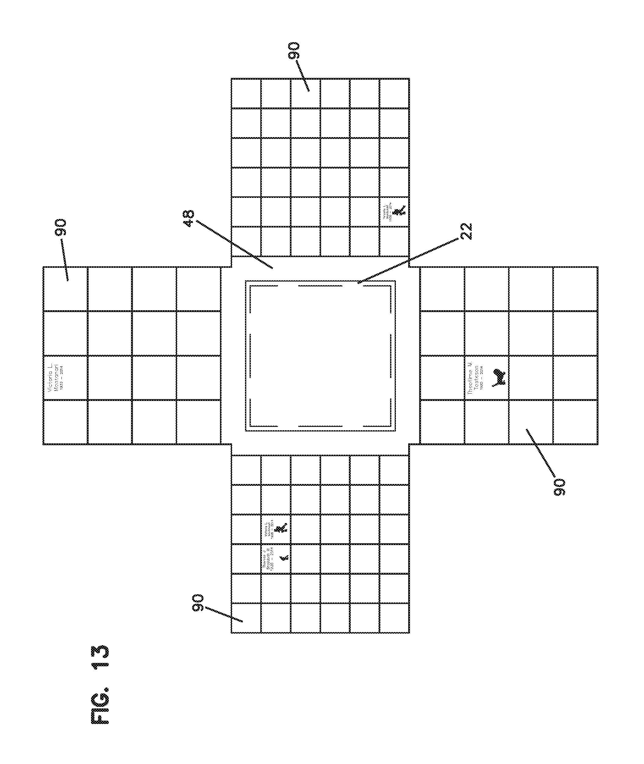
[0060] Referring to FIG. 12, in a first alternate embodiment, the obelisk (22) may be situated with natural materials such as soil surrounding the base (48). The beam (68) is sunken into the ground and covered with soil. The ground surface surrounding the obelisk (22) may include decorative gravel, grass, flowers or other decorative landscaping. As shown in FIG. 13, decorative pavers (90) may be placed around the obelisk (22). The pavers (90) may be used for inscriptions to memorialize those interred. Moreover, plaques and other ground treatments may also be utilized. Moreover, the obelisk can be configured to with different heights, widths and tapers. The obelisk may also be configured with 5, 6 or more sides.
[0061] Referring to FIG. 14, it can be appreciated that the present invention in an alternate mounting arrangement, a further embodiment (200) may simply include a depositing pedestal (202) to access the underground vessel (70). The pedestal (202) includes a chute (204) with an opening (206) and a cover (208). Remains may simply be placed into the opening (206) and then drop through the chute into the container vessel (70) in a manner similar to that for the embodiment shown in FIGS. 1-9. An obelisk, columbarium or other structure above ground may include inscriptions for names of those interred in the system (200). Moreover, depending upon capacities, multiple columbaria and/or other above ground structures for inscriptions may be associated with a single underground repository (26). The present invention therefore requires less space and has greater flexibility to adapt to the needs of the installment and provide layouts that may be adapted to the particular space.
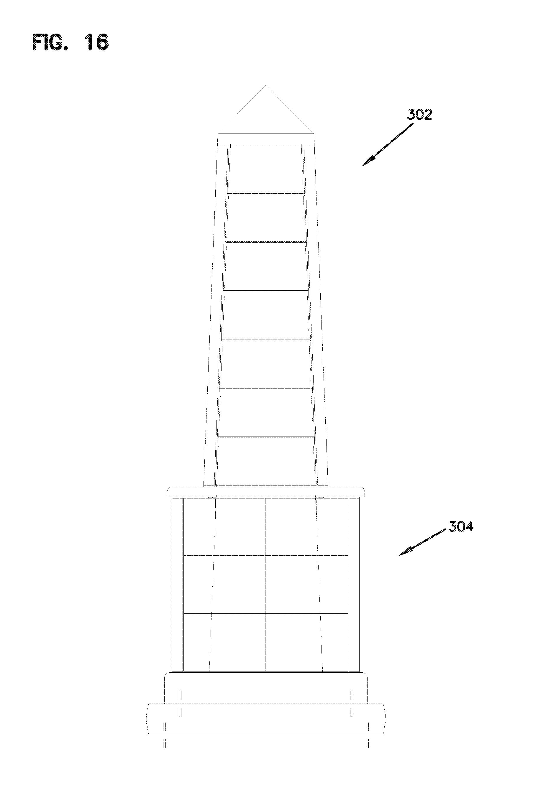
[0062] Referring now to FIGS. 15-18, there is shown a fourth embodiment of an ossuary internment system (300). The system (300) generally includes an above ground obelisk type columbarium (302), a delivery system (24) and an underground repository (326). As with other embodiments, the obelisk structure (302) generally includes outer facing panels (36), niches (34), walls and floor/ceiling elements (44) for storing remains and urns or other appropriate containers. In the embodiment of FIGS. 15-18, the obelisk (302) mounts on a widened lower base section (304). The lower section (304) generally includes outer facing panels (36), niches (34), walls and floor/ceiling elements (44) for storing remains and urns or other appropriate containers. The obelisk structure (302) includes an access niche and the lower section (302) also provides for having a chute (54) pass there through to a repository (26), as shown in FIG. 18. In the embodiment shown in FIGS. 15-18, the lower section has a rectangular cross-section, however other shapes are possible. Moreover, the obelisk has 13 niches and the lower section (304) has 12 niches for a total of 25 niches. Other configurations are possible with different combinations and different numbers of total niches.
[0063] As shown in FIG. 15, the underground repository structure (26) includes a supporting framework. The repository structure (26) includes a beam (308) supported on posts (314). The posts (314) may be rectangular and may be cast, stacked elements, poured concrete, block-type pillars or other well-known structures providing support for the beam. The posts (314) may have a round, square, rectangular or any other conventional cross-section. The beam (308) includes an opening with the chute (54) passing vertically there through. As shown in FIG. 7, the waterproof container vessel (70) is supported on an anti-floatation platform (74). As the vessel (70) is sealed and waterproof, weight may need to be added through attachment to the platform to prevent the container vessel (70) from floating should the ground become saturated due to heavy rain or other wet conditions.
[0064] Referring now to FIGS. 19-22, there is shown a fifth embodiment of an ossuary internment system (400). The system (400) generally includes an above ground obelisk type columbarium (402), a lower base section (404), a delivery system (24) and an underground repository (426). The system (400) is similarly configured to the embodiment shown in FIGS. 15-18, with the same elements, but has a different size. The obelisk (402) has 13 niches and the lower section (404) has 16 niches for a total of 29 niches. Other configurations are possible with different combinations and different numbers of total niches.
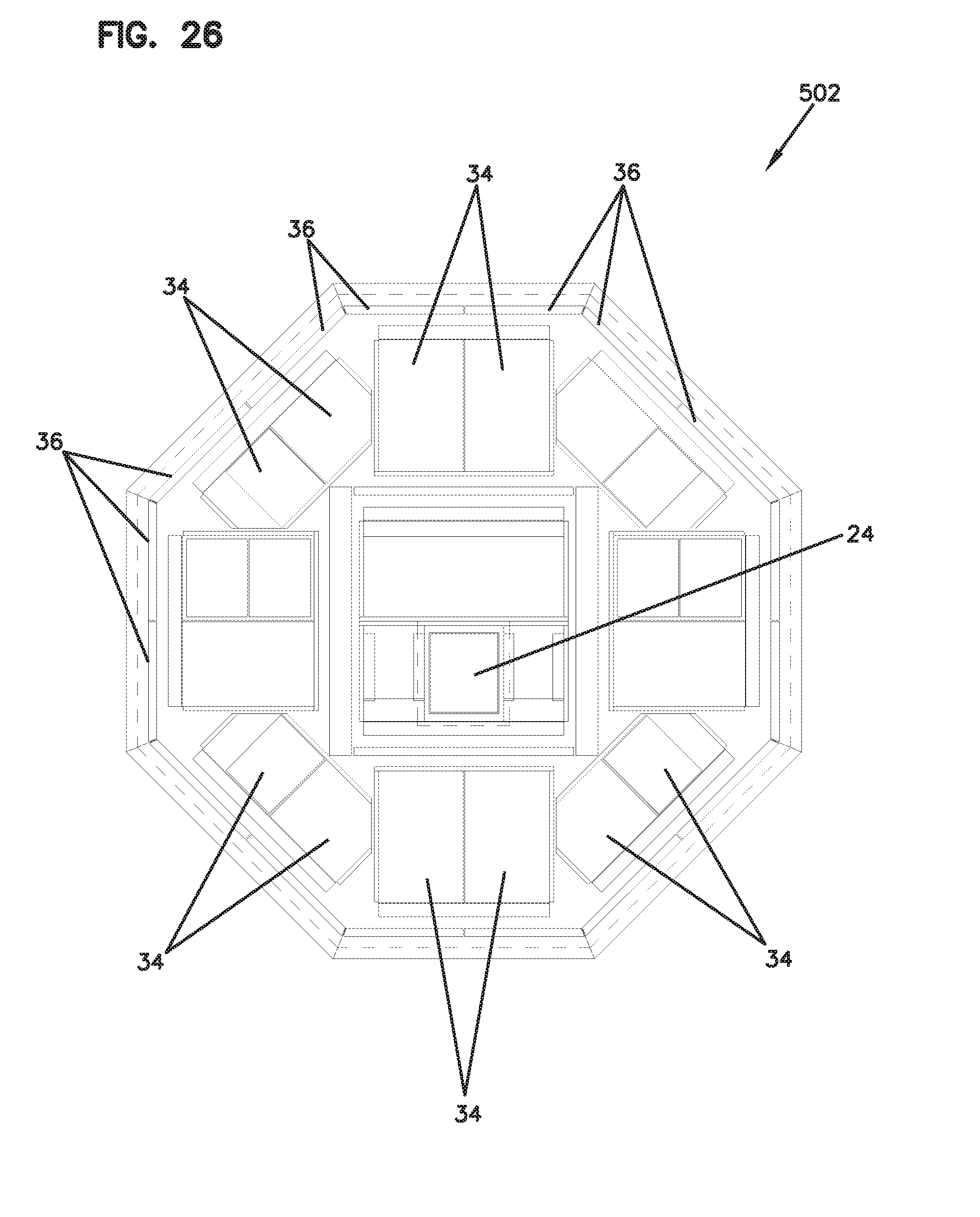
[0065] Referring now to FIGS. 23-26, there is shown a sixth embodiment of an ossuary internment system (500). The system (500) generally includes an above ground obelisk type columbarium (502), a lower base section (504), a delivery system (24) and an underground repository (526). The system (500) is similarly configured to the embodiment shown in FIGS. 15-18, with the same elements, but has a different size and the lower section (504) has a different shape. As shown most clearly in FIG. 26, the lower section (504) has an octagonal cross-section. The obelisk (502) has 13 niches and the lower section (504) has 48 niches for a total of 61 niches. Other configurations are possible with different combinations and different numbers of total niches.
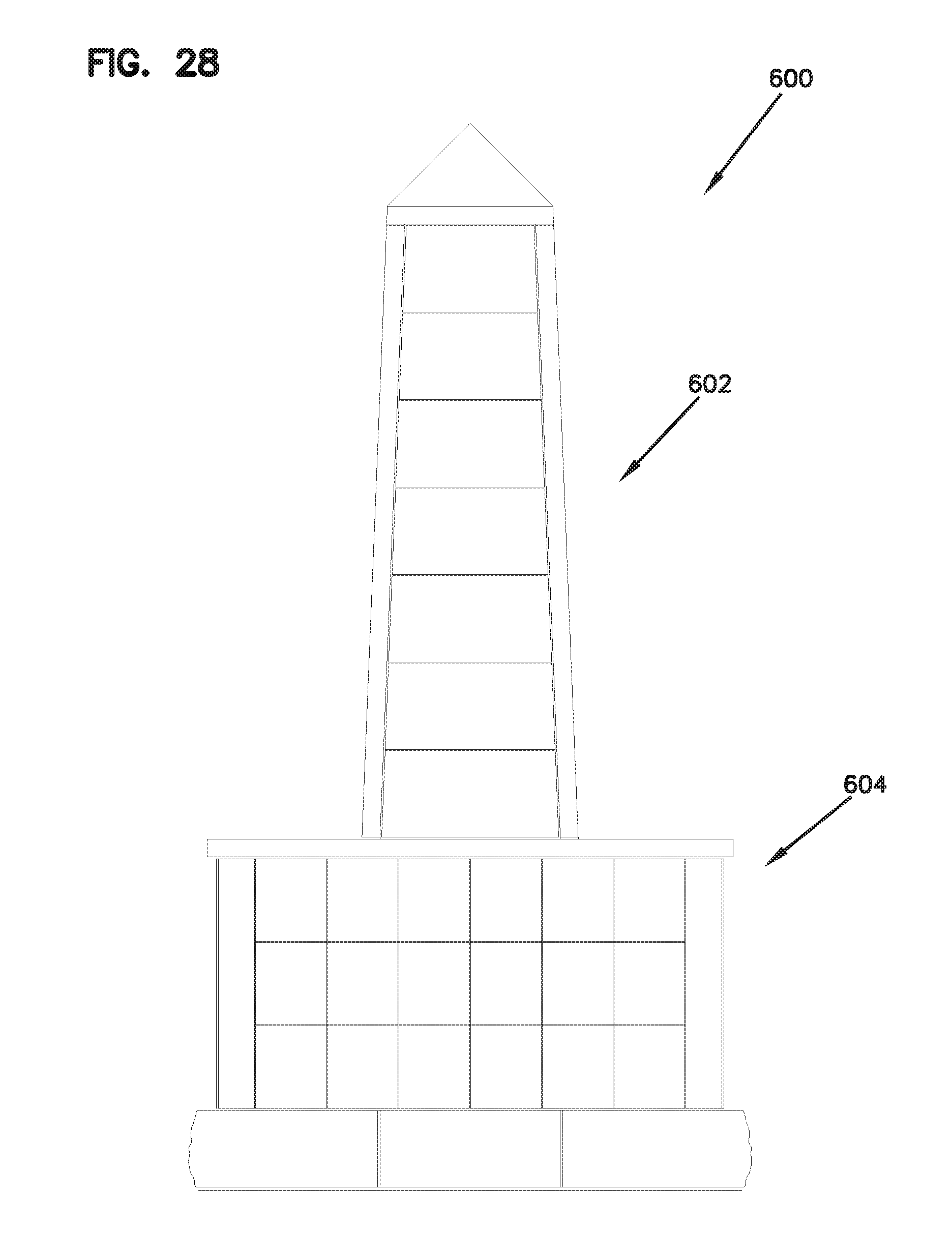
[0066] Referring now to FIGS. 27-30, there is shown a seventh embodiment of an ossuary internment system (600). The system (600) generally includes an above ground obelisk type columbarium (602), a lower base section (604), a delivery system (24) and an underground repository (626). The system (600) is similarly configured to the embodiment shown in FIGS. 15-18, with the same elements, but has a different size. The obelisk (602) has 13 niches and the lower section (604) has 54 niches for a total of 67 niches. Other configurations are possible with different combinations and different numbers of total niches.
[0067] Referring now to FIGS. 31-34, there is shown an eighth embodiment of an ossuary internment system (700). The system (700) generally includes an above ground obelisk type columbarium (702), a lower base section (704), a delivery system (24) and an underground repository (726). The system (700) is similarly configured to the embodiment shown in FIGS. 15-18, with the same elements, but has a different size. The obelisk (702) has 13 niches and the lower section (704) has 54 niches for a total of 67 niches. Other configurations are possible with different combinations and different numbers of total niches.
[0068] Referring now to FIGS. 35-39, there is shown a ninth embodiment of an ossuary internment system (800). The system (800) generally includes an above ground columbarium (802), a delivery system (24) and an underground repository (826). Rather than an obelisk shaped structure, the columbarium (802) has generally vertical walls and a rectangular cross section. The obelisk (802) has 93 niches. Other configurations are possible with different combinations and different numbers of total niches. As with other embodiments, the columbarium structure (802) generally includes outer facing panels (36), niches (34), walls and floor/ceiling elements (44) for storing remains and urns or other appropriate containers. The columbarium (802) includes an access niche and a chute (54) as shown in FIGS. 37 and 39.
[0069] As shown in FIGS. 35 and 36, the facing panels (36) may have different appearances, such as a contrasting appearance, and can be configured to create a desired pattern. As shown in FIGS. 35 and 36, a cross pattern (810) is created on the exterior of the columbarium (802). Moreover, other patterns and designs may be created through outer panels with different appearances.
[0070] It is to be understood, however, that even though numerous characteristics and advantages of the present invention have been set forth in the foregoing description, together with details of the structure and function of the invention, the disclosure is illustrative only, and changes may be made in detail, especially in matters of shape, size and arrangement of parts within the principles of the invention to the full extent indicated by the broad general meaning of the terms in which the appended claims are expressed.
* * * * *
D00000
D00001
D00002
D00003
D00004
D00005
D00006
D00007
D00008
D00009
D00010
D00011
D00012
D00013

D00014

D00015
D00016
D00017

D00018

D00019

D00020

D00021

D00022

D00023

D00024

D00025
D00026

D00027
D00028

D00029

D00030

D00031

D00032

D00033

D00034

D00035
D00036
D00037

D00038

XML
uspto.report is an independent third-party trademark research tool that is not affiliated, endorsed, or sponsored by the United States Patent and Trademark Office (USPTO) or any other governmental organization. The information provided by uspto.report is based on publicly available data at the time of writing and is intended for informational purposes only.
While we strive to provide accurate and up-to-date information, we do not guarantee the accuracy, completeness, reliability, or suitability of the information displayed on this site. The use of this site is at your own risk. Any reliance you place on such information is therefore strictly at your own risk.
All official trademark data, including owner information, should be verified by visiting the official USPTO website at www.uspto.gov. This site is not intended to replace professional legal advice and should not be used as a substitute for consulting with a legal professional who is knowledgeable about trademark law.