Conductive Aerogel
Lozano; Paulo C. ; et al.
U.S. patent application number 14/661855 was filed with the patent office on 2016-12-29 for conductive aerogel. The applicant listed for this patent is Massachusetts Institute of Technology. Invention is credited to Steven Mark Arestie, Paulo C. Lozano.
| Application Number | 20160376150 14/661855 |
| Document ID | / |
| Family ID | 57601525 |
| Filed Date | 2016-12-29 |


View All Diagrams
| United States Patent Application | 20160376150 |
| Kind Code | A1 |
| Lozano; Paulo C. ; et al. | December 29, 2016 |
CONDUCTIVE AEROGEL
Abstract
Electrically conductive aerogel and methods of making the same are disclosed. A solution is provided. The solution is cured to form a polymer. The polymer is carbonized to form the conductive aerogel.
| Inventors: | Lozano; Paulo C.; (Arlington, MA) ; Arestie; Steven Mark; (Boston, MA) | ||||||||||
| Applicant: |
|
||||||||||
|---|---|---|---|---|---|---|---|---|---|---|---|
| Family ID: | 57601525 | ||||||||||
| Appl. No.: | 14/661855 | ||||||||||
| Filed: | March 18, 2015 |
Related U.S. Patent Documents
| Application Number | Filing Date | Patent Number | ||
|---|---|---|---|---|
| 61986645 | Apr 30, 2014 | |||
| Current U.S. Class: | 264/80 |
| Current CPC Class: | C04B 35/64 20130101; B29C 71/02 20130101; C04B 35/528 20130101; C01B 32/05 20170801; B29C 39/02 20130101; H01J 37/08 20130101; F03H 1/0006 20130101; H01J 1/05 20130101; H01J 9/02 20130101; C01P 2006/40 20130101 |
| International Class: | C01B 31/02 20060101 C01B031/02 |
Goverment Interests
GOVERNMENT SUPPORT
[0003] This invention was made with government support under Contract No. FA2386-11-1-4074 awarded by the Air Force Office of Scientific Research. The government has certain rights in the invention.
Claims
1. A method of fabricating an electrically conductive aerogel comprising: providing a solution; curing the solution to form a polymer; and carbonizing the polymer to form the conductive aerogel.
2. The method of claim 1, further comprising: forming the solution by combining at least deionized water, formaldehyde, resorcinol, and acetic acid.
3. The method of claim 1, wherein carbonizing the polymer to form the conductive aerogel comprises: pyrolyzing the polymer.
4. The method of claim 1, wherein carbonizing the polymer to form the conductive aerogel comprises: pyrolyzing the polymer in an environment comprising at least one of carbon dioxide, nitrogen, and argon.
5. A method of fabricating an electrically conductive aerogel comprising: providing a solution; inserting a wire into the solution; curing the solution to form a polymer with the wire embedded in the polymer; and carbonizing the polymer to form the conductive aerogel.
6. The method of claim 5, further comprising: forming the solution by combining at least deionized water, formaldehyde, resorcinol, and acetic acid.
7. The method of claim 5, wherein carbonizing the polymer to form the conductive aerogel comprises: pyrolyzing the polymer.
8. The method of claim 5, wherein carbonizing the polymer to form the conductive aerogel comprises: pyrolyzing the polymer in an environment comprising at least one of carbon dioxide, nitrogen, and argon.
9. The method of claim 5, wherein the wire comprises stainless steel, nickel chromium, or platinum.
10. A method of fabricating an electrically conductive aerogel comprising: providing a solution; providing a mold; pouring the solution into the mold; curing the solution in the mold to form a polymer; and carbonizing the polymer to form the electrically conductive aerogel.
11. The method of claim 10, further comprising: forming the solution by combining at least deionized water, formaldehyde, resorcinol, and acetic acid.
12. The method of claim 10, wherein carbonizing the polymer to form the electrically conductive aerogel comprises: pyrolyzing the polymer.
13. The method of claim 10, wherein carbonizing the polymer to form the electrically conductive aerogel comprises: pyrolyzing the polymer in an environment comprising at least one of carbon dioxide, nitrogen, and argon.
14. A method of fabricating an electrically conductive aerogel comprising: providing a solution; providing a mold; suspending a wire in the mold; pouring the solution into the mold, such that at least a portion of the wire is submerged in the solution; curing the solution in the mold to form a polymer, wherein the wire is embedded in the polymer; and carbonizing the polymer with the wire embedded to form the electrically conductive aerogel.
15. The method of claim 14, further comprising: forming the solution by combining at least deionized water, formaldehyde, resorcinol, and acetic acid.
16. The method of claim 14, wherein carbonizing the polymer with the wire embedded to form the electrically conductive aerogel comprises: pyrolyzing the polymer.
17. The method of claim 14, wherein carbonizing the polymer with the wire embedded to form the electrically conductive aerogel comprises: pyrolyzing the polymer in an environment comprising at least one of carbon dioxide, nitrogen, and argon.
18. The method of claim 14, wherein the wire comprises stainless steel, nickel chromium, or platinum.
19. A method of fabricating a porous distal electrode for an electrospray thruster comprising: providing a solution; providing a distal electrode mold; suspending a wire in the distal electrode mold; pouring the solution into the distal electrode mold, such that at least a portion of the wire is submerged in the solution; curing the solution in the distal electrode mold to form a polymer, wherein the wire is embedded in the polymer; and carbonizing the polymer with the wire embedded to form the porous distal electrode.
Description
CROSS-REFERENCE TO RELATED APPLICATION
[0001] This application claims the benefit of and priority to U.S. Patent Application No. 61/986,645, filed Apr. 30, 2014, the entire contents of which are incorporated herein by reference in their entirety.
[0002] The contents of U.S. patent application Ser. No. 14/070,351, filed on Nov. 1, 2013; U.S. patent application Ser. No. 13/839,064, filed on Mar. 15, 2013; U.S. patent application Ser. No. 13/681,155, filed on Nov. 19, 2012; U.S. patent application Ser. No. 12/990,923, filed on May 3, 2011; PCT application No. PCT/US2009/042990, filed on May 6, 2009; U.S. provisional patent Application No. 61/050,847, filed on May 6, 2008; and U.S. Patent Application No. 61/695,034, filed Aug. 30, 2012 are incorporated herein by reference in their entirety.
FIELD OF THE TECHNOLOGY
[0004] The present technology relates generally to aerogel and, more specifically, to conductive aerogel.
BACKGROUND
[0005] Porous materials can be used in a variety of applications. For example, Ion sources, such as those described in U.S. patent application Ser. No. 13/839,064, can utilize porous materials for various components. For example, in the ion sources described in U.S. patent application Ser. No. 13/839,064, a distal electrode can be made of a porous material.
SUMMARY OF THE TECHNOLOGY
[0006] Accordingly, there is a need for electrically conductive porous materials. In one aspect, there is a method of fabricating an electrically conductive aerogel. The method includes providing a solution. The method includes curing the solution to form a polymer. The method includes carbonizing the polymer to form the conductive aerogel. In some embodiments, the method includes forming the solution by combining at least deionized water, formaldehyde, resorcinol, and acetic acid. In some embodiments, the solution is formed by combining, by mass, 34.09 parts deionized water, 40.68 parts formaldehyde, 27.95 parts resorcinol, and 1 part acetic acid. In some embodiments, curing the solution to form the polymer includes curing the solution in a sealed container at approximately 60.degree. C. to 85.degree. C. In some embodiments, carbonizing the polymer to form the conductive aerogel includes pyrolyzing the polymer. In some embodiments, carbonizing the polymer to form the conductive aerogel includes pyrolyzing the polymer in an environment including at least one of carbon dioxide, nitrogen, and argon. In some embodiments, the electrically conductive aerogel has a surface area of at least 400 m.sup.2 per gram.
[0007] In another aspect, there is a method of fabricating an electrically conductive aerogel. The method includes providing a solution. The method includes inserting a wire into the solution. The method includes curing the solution to form a polymer with the wire embedded in the polymer. The method includes carbonizing the polymer to form the conductive aerogel. In some embodiments, the method includes forming the solution by combining at least deionized water, formaldehyde, resorcinol, and acetic acid. In some embodiments, the solution is formed by combining, by mass, 34.09 parts deionized water, 40.68 parts formaldehyde, 27.95 parts resorcinol, and 1 part acetic acid. In some embodiments, curing the solution to form the polymer includes curing the solution in a sealed container at approximately 60.degree. C. to 85.degree. C. In some embodiments, carbonizing the polymer to form the conductive aerogel includes pyrolyzing the polymer. In some embodiments, carbonizing the polymer to form the conductive aerogel includes pyrolyzing the polymer in an environment including at least one of carbon dioxide, nitrogen, and argon. In some embodiments, the electrically conductive aerogel has a surface area of at least 400 m.sup.2 per gram. In some embodiments, the wire comprises stainless steel, nickel chromium, or platinum.
[0008] In another aspect, there is a method of fabricating an electrically conductive aerogel. The method includes providing a solution. The method includes providing a mold. The method includes pouring the solution into the mold. The method includes curing the solution in the mold to form a polymer. The method includes carbonizing the polymer to form the electrically conductive aerogel. In some embodiments, the method includes forming the solution by combining at least deionized water, formaldehyde, resorcinol, and acetic acid. In some embodiments, the solution is formed by combining, by mass, 34.09 parts deionized water, 40.68 parts formaldehyde, 27.95 parts resorcinol, and 1 part acetic acid. In some embodiments, curing the solution in the mold to form the polymer includes curing the solution in a sealed container at approximately 60.degree. C. to 85.degree. C. In some embodiments, carbonizing the polymer to form the electrically conductive aerogel includes pyrolyzing the polymer. In some embodiments, carbonizing the polymer to form the electrically conductive aerogel includes pyrolyzing the polymer in an environment including at least one of carbon dioxide, nitrogen, and argon. In some embodiments, the electrically conductive aerogel has a surface area of at least 400 m.sup.2 per gram.
[0009] In another aspect, there is a method of fabricating an electrically conductive aerogel. The method includes providing a solution. The method includes providing a mold. The method includes suspending a wire in the mold. The method includes pouring the solution into the mold, such that at least a portion of the wire is submerged in the solution. The method includes curing the solution in the mold to form a polymer, wherein the wire is embedded in the polymer. The method includes carbonizing the polymer with the wire embedded to form the electrically conductive aerogel. In some embodiments, the method includes forming the solution by combining at least deionized water, formaldehyde, resorcinol, and acetic acid. In some embodiments, the solution is formed by combining, by mass, 34.09 parts deionized water, 40.68 parts formaldehyde, 27.95 parts resorcinol, and 1 part acetic acid. In some embodiments, curing the solution in the mold to form the polymer includes curing the solution in a sealed container at approximately 60.degree. C. to 85.degree. C. In some embodiments, carbonizing the polymer with the wire embedded to form the electrically conductive aerogel includes pyrolyzing the polymer. In some embodiments, carbonizing the polymer with the wire embedded to form the electrically conductive aerogel includes pyrolyzing the polymer in an environment including at least one of carbon dioxide, nitrogen, and argon. In some embodiments, the electrically conductive aerogel has a surface area of at least 400 m.sup.2 per gram. In some embodiments, the wire comprises stainless steel, nickel chromium, or platinum.
[0010] In another aspect, there is a method of fabricating a porous distal electrode for an electrospray thruster. The method includes providing a solution. The method includes providing a distal electrode mold. The method includes suspending a wire in the distal electrode mold. The method includes pouring the solution into the distal electrode mold, such that at least a portion of the wire is submerged in the solution. The method includes curing the solution in the distal electrode mold to form a polymer, wherein the wire is embedded in the polymer. The method includes carbonizing the polymer with the wire embedded to form the porous distal electrode. In another aspect, there is an electrically conductive aerogel prepared by a process including the steps: providing a solution; curing the solution to form a polymer; and carbonizing the polymer to form the conductive aerogel. In another aspect, there is an electrically conductive aerogel prepared by a process including the steps: providing a solution; inserting a wire into the solution; curing the solution to form a polymer with the wire embedded in the polymer; and carbonizing the polymer to form the conductive aerogel. In another aspect, there is an electrically conductive aerogel prepared by a process including the steps: providing a solution; providing a mold; suspending a wire in the mold; pouring the solution into the mold, such that at least a portion of the wire is submerged in the solution; curing the solution in the mold to form a polymer, wherein the wire is embedded in the polymer; and carbonizing the polymer with the wire embedded to form the electrically conductive aerogel.
[0011] In another aspect, there is a porous distal electrode for an electrospray thruster prepared by a process including the steps: providing a solution; providing a distal electrode mold; suspending a wire in the distal electrode mold; pouring the solution into the distal electrode mold, such that at least a portion of the wire is submerged in the solution; curing the solution in the distal electrode mold to form a polymer, wherein the wire is embedded in the polymer; and carbonizing the polymer with the wire embedded to form the porous distal electrode. In another aspect, there is a porous distal electrode for an electrospray thruster. The porous distal electrode includes a body including porous, electrically conductive aerogel. The porous distal electrode includes a wire at least partially embedded in the body.
[0012] Other aspects and advantages of the present technology will become apparent from the following detailed description, taken in conjunction with the accompanying drawings, illustrating the principles of the technology by way of example only.
BRIEF DESCRIPTION OF THE DRAWINGS
[0013] The foregoing and other objects, features, and advantages of the present technology, as well as the technology itself, will be more fully understood from the following description of various embodiments, when read together with the accompanying drawings, in which:
[0014] FIG. 1A-FIG. 1C illustrate an exemplary molding process in accordance with the technology.
[0015] FIG. 2 is a flowchart illustrating a curing process.
[0016] FIG. 3 is a graph illustrating the temperature of a tube furnace during carbonization.
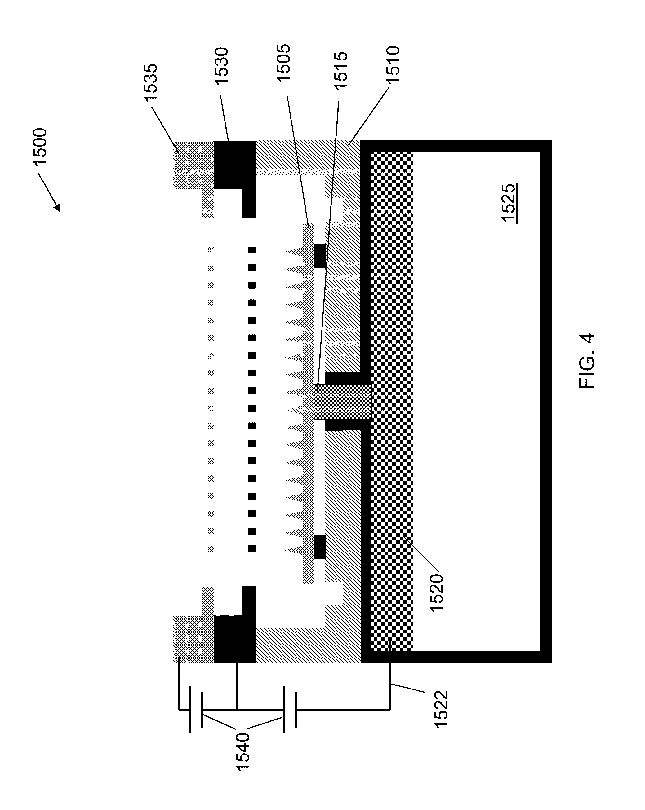
[0017] FIG. 4 is a schematic of an electrospray ion source.
[0018] FIG. 5 is a schematic of a thruster.
[0019] FIG. 6 illustrates a distal electrode placed in a thruster tank.
[0020] FIG. 7 illustrates an electrode, including a wire embedded in carbon aerogel.
[0021] FIG. 8 illustrates an electrode, including a wire embedded in carbon aerogel.
[0022] FIG. 9 illustrates an electrode after curing, an electrode after carbonization, and a final product electrode.
[0023] FIG. 10 depicts a mold for forming electrodes.
[0024] FIG. 11 depicts pre-carbonization, post-cure electrodes out of mold.
DETAILED DESCRIPTION
[0025] The technology disclosed herein relates to electrically conductive aerogel (e.g., acetic acid catalyzed carbon aerogels), and methods of fabricating the aerogel. The technology includes methods to embed wires into the aerogel (e.g., by allowing a gel to form and cure around the wires). The wires can provide electrical and/or mechanical contacts for the aerogel.
Exemplary Fabrication Methods
[0026] Fabrication of conductive aerogel can include preparing a solution, molding, embedding a wire, curing, carbonization, and shaping and/or polishing, each of which is described in greater detail below.
Solution Preparation
[0027] In some embodiments, conductive aerogel fabrication can include preparing a solution including deionized water, formaldehyde, resorcinol, and acetic acid. For example, the solution can be formed from the following components in the indicated proportions by mass: deionized water (34.09), formaldehyde (40.68), resorcinol (27.95), and acetic acid (1). The resorcinol can be added to the deionized water and mixed until fully dissolved. The formaldehyde can be added to the solution, and the solution can be mixed (e.g., the solution can be thoroughly mixed for approximately a minute). The acetic acid can be added to the solution, and the solution can be mixed (e.g., the solution can be thoroughly mixed for approximately a minute). In some applications, prior to gelation and hardening, the solution can be poured into molds.
Molding and Embedding Wire
[0028] The solution described above can be placed in molds to form aerogel specimens, as appropriate for the intended application. A wire can be inserted into the solution. FIG. 1A-FIG. 1C illustrate an exemplary molding process in accordance with the technology. A cross-section of an exemplary mold 105 is illustrated. Mold 105 can be any mold made in the desired shape for the aerogel specimen. In some embodiments, an oversized mold can be used to account for shrinkage that occurs during the curing process. Mold 105 can be made of any suitable material for withstanding the curing process described below. In some embodiments, mold 105 can be made from polypropylene or RTV silicone. In some embodiments, mold 105 can include mounts 110. Mounts 110 can be used to mount wire 115, such that wire 115 can be suspended in mold 105. Wire 115 can be made of any suitable material for withstanding the curing process described below. In some embodiments, wire 115 can be made from stainless steel, nickel chromium, and/or platinum.
[0029] As illustrated in FIG. 1B, solution 120 can be poured into mold 105. Solution 120 can be a solution of deionized water, formaldehyde, resorcinol, and acetic acid, as described above. Wire 115 can be placed in mold 105 such that wire 115 is at least partially submerged in solution 120. Preferably, wire 115 can be inserted into solution 120 before solution 120 gels.
Curing
[0030] Conductive aerogel fabrication can include curing the solution described above (e.g., the solution can be cured in molds). In some instances, curing can take approximately one week. Airtight or sealed containers (e.g., commercially available SNAPWARE containers) can be used during the curing process. For example, with reference to FIG. 1B, solution 120 in mold 105 containing can be cured to harden solution 120 with wire 115 in place as described below.
[0031] FIG. 2 is a flowchart illustrating a curing process. In accordance with embodiments of the technology, the solution (e.g., while in molds) can be placed in an airtight container at room temperature conditions (e.g., approximately 72.degree. F.) and allowed to rest for 48 hours (step 210). During this period, the solution can turn from a clear liquid to an opaque white liquid. The solution can slowly become more viscous until it appears to be a solid gel. The opaque white gel can then start turning a light orange color.
[0032] The airtight container containing the gel can then be placed in an oven and cured at approximately 35-40.degree. C. for approximately 24 hours (step 220). During this curing step, the gel can begin turning a darker orange/red color. The oven temperature can then be increased to approximately 60.degree. C., and the gel can cure at approximately 60.degree. C. for approximately 24 hours (step 230). During this curing step, the gel can continue to get darker orange and/or red. The oven temperature can then be increased to approximately 85.degree. C., and the gel can cure at approximately 85.degree. C. for at least approximately 72 hours (step 240). During this curing step, the gel can continue to get darker orange and/or red.
[0033] The container containing the gel can be removed from the oven and allowed to cool for approximately two hours at approximately room temperature (step 250). The gel can be saturated with acetone (step 260), and allowed to rest until all of the acetone has evaporated (step 270). To complete the curing process, the open container containing the gel can be placed in an oven and cured at approximately 85.degree. C. for at least approximately 24 hours (step 280). The above described curing process can produce a red, porous polymer. The polymer can be removed from the mold at the conclusion of curing (e.g., as illustrated by porous polymer 130 of FIG. 1C).
Carbonization
[0034] The polymer produced by the curing process described is non-conductive. In some embodiments of the technology, a carbonization step can be used to turn the polymer into a porous and conductive carbon material. In some embodiments, the polymer can be carbonized in the mold used during the curing process. In some embodiments, the polymer can be removed from the mold used during the curing process prior to carbonization. For example, the polymer can be carbonized by a pyrolyzation process. The polymer can be carbonized by placing it in a tube furnace at high temperature. In some embodiments, the tube furnace has a steady flow of inert gas (e.g., nitrogen or argon) at approximately 500 standard cubic centimeters per minute (sccm). In some embodiments, the temperature of the tube furnace containing the polymer can be slowly increased and decreased during the carbonization process. FIG. 3 is a graph illustrating the temperature of a tube furnace during carbonization. From time 305 to 310 (e.g., approximately 2 hours), the temperature of the tube furnace containing the polymer is increased to approximately 1000.degree. C. From time 310 to 315 (e.g., approximately 4 hours), the temperature of the tube furnace containing the polymer is maintained at approximately 1000.degree. C. From time 315 to 320 (e.g., approximately 4 hours), the temperature of the tube furnace containing the polymer is decreased to approximately 20.degree. C. The above described curing carbonization process can produce an electrically conductive, porous carbon aerogel.
[0035] In some embodiments, carbon dioxide can be flowed over the specimen as it is heated in a tube furnace. Such a process can increase internal surface area of the aerogel by approximately an order of magnitude.
Polishing and/or Shaping
[0036] Aerogel fabrication can include polishing and/or shaping the aerogel, as appropriate for the desired application. The molding process described above allows for a slightly oversized aerogel specimen, which permits it to be polished to the desired shape. Polishing can be done, for example, with high-grit sandpaper.
Exemplary Applications
[0037] The aerogel described herein can be incorporated into a variety of applications, such as in electrospray thrusters, electrospray emitters, and batteries. Beneficially, the aerogel can provide a large internal surface area (e.g., approximately 400 m.sup.2 or more per gram of the aerogel) with low density (e.g., approximately 0.5 g/cc). As described above, the fabrication methods can facilitate molding the aerogel into a variety of shapes, and the embedded wire can provide a mechanical and/or electric contact.
[0038] In an exemplary application, carbon aerogel can be used as a distal electrode in an electrospray thruster. Electrospray thrusters utilizing distal electrodes are described in greater detail in U.S. application Ser. No. 13/839,064, filed on Mar. 15, 2013, the contents of which are hereby incorporated by reference. FIG. 4 is a schematic of an electrospray ion source 1500. Ion source 1500 includes emitter array 1505. Emitter array 1505 is housed in thruster package 1510 (made from e.g., silicon). Emitter array 1505 is disposed against porous plug/isolation valve 1515. Porous plug/isolation valve 1515 is disposed against distal electrode 1520. Distal electrode 1520 can be made from carbon aerogel with embedded wire 1522 providing an electrical contact. Porous plug/isolation valve 1515 can serve as a connecting member between emitter array 1505 and distal electrode 1520. Distal electrode 1520 is in contact with ionic liquid 1525. In some embodiments, each of emitter array 1505, porous plug/isolation valve 1515, and distal electrode 1520 can include a pore size gradient that decreases from its base to its top (e.g., in the direction toward the tips of needle emitter array 1505), such that ionic liquid can be transported through capillarity. In some embodiments, emitter array 1505 can have smaller-sized pores than porous plug/isolation valve 1515, which in turn can have smaller-sized pores than distal electrode 1520, creating a pore size gradient that decreases from distal electrode 1520 to emitter array 1505, such that ionic liquid 1525 can be transported through capillarity from distal electrode 1520 to emitter array 1505.
[0039] Extractor electrode 1530 can be positioned downstream relative to emitter array 1505. Accelerator grid 1535 can be position downstream relative to extractor grid 1530. Bipolar power source 1545 can apply a voltage to distal electrode 1520 relative to extractor electrode 1530, thereby emitting a current (e.g., a beam of ions) from the tips of emitter array 1505. The application of a voltage can cause the emission of ions from emitter array 1505. FIG. 5 is a schematic of thruster 500. Similar to that described with respect to FIG. 4, thruster 500 includes distal electrode 510 including embedded wire 515. Distal electrode 510 can be made from carbon aerogel as described above. FIG. 6 illustrates distal electrode 605 placed in thruster tank 610. In the illustrated embodiment, distal electrode 605 is formed from carbon aerogel. After electrode 605 is shaped into the correct geometry, wire 615 is inserted into a small hole in the side of tank 610 and electrode 605 follows until it is all the way in tank 610. In some embodiments, electrode 605 can be flush with the top face (same face where the thruster package attaches) of tank 610.
[0040] Beneficially, a distal electrode made from carbon aerogel provides a large contact area with the ionic liquid propellant. The large surface area can act like a capacitor capable of accumulating charge at the interface between the distal electrode material and the ionic liquid (e.g., which permeates into the pores of the distal electrode). The dispersed charge can facilitate keeping the level of local charge lower (e.g., while charge across the aerogel is large, it is spread out across a large surface area, and locally the charge is relatively small) such that the electric field at the distal electrode/ionic liquid interface is not strong enough to trigger electrochemical reactions. In some applications, before charge sufficient to cause electrochemical reactions is accumulated on the surface of the electrode, the polarity of the thruster is reversed, to deplete the charge and start a new charging cycle in the opposite polarity.
[0041] Beneficially, if some electrochemistry were to occur at the distal electrode, its effects can be confined to the electrode, which can have a large enough area to survive while leaving the emitter substrate material untouched by the electrochemical reactions, thus increasing the lifetime of the emitter substrate that produces the ion beams.
Experimental Results
[0042] FIG. 7 illustrates electrode 700, including wire 705 embedded in carbon aerogel 710. In the illustrated embodiment, the fabrication process described above was used. Wire 705 is made from stainless steel. It was found that stainless steel was able to tolerate the high temperatures in the fabrication process. The approximate dimensions of electrode 700 are 10 mm.times.6 mm.times.2 mm in thickness. It was determined that the stainless steel wires were stiff and brittle after the high temperature carbonization step.
[0043] FIG. 8 illustrates electrode 800, including wire 805 embedded in carbon aerogel 810. In the illustrated embodiment, wire 805 is made from Nickel Chromium (Nichrome). Nichrome can be less brittle at the high temperatures and can have more soldering options than stainless steel. Electrode 800 has approximate dimensions 7 mm by 10 mm by 2 mm in thickness. In the illustrated embodiment, the dimensions of electrode 800 are selected to facilitate incorporating electrode 800 into a thruster tank, e.g., as illustrated above. FIG. 9 illustrates an electrode after curing (905), an electrode after carbonization (910), and a final product electrode (915).
[0044] FIG. 10 depicts mold 1005 for forming electrodes. Mold 1005 is a custom machined mold that allows for the production of 40 electrodes at a time. For example, mold 1005 can produce electrodes of approximate dimensions of electrode 600 are 10 mm.times.6 mm.times.2 mm thick. FIG. 11 depicts pre-carbonization, post-cure electrodes out of mold 1005.
[0045] The technology has been described in terms of particular embodiments. The alternatives described herein are examples for illustration only and not to limit the alternatives in any way. The steps of the technology can be performed in a different order and still achieve desirable results. Other embodiments are within the scope of the following claims.
* * * * *
D00000
D00001
D00002
D00003
D00004
D00005
D00006
D00007
D00008
D00009
D00010
D00011
XML
uspto.report is an independent third-party trademark research tool that is not affiliated, endorsed, or sponsored by the United States Patent and Trademark Office (USPTO) or any other governmental organization. The information provided by uspto.report is based on publicly available data at the time of writing and is intended for informational purposes only.
While we strive to provide accurate and up-to-date information, we do not guarantee the accuracy, completeness, reliability, or suitability of the information displayed on this site. The use of this site is at your own risk. Any reliance you place on such information is therefore strictly at your own risk.
All official trademark data, including owner information, should be verified by visiting the official USPTO website at www.uspto.gov. This site is not intended to replace professional legal advice and should not be used as a substitute for consulting with a legal professional who is knowledgeable about trademark law.