Rotary Open/close-type Tube Container
Jung; Seo-Hui
U.S. patent application number 15/125137 was filed with the patent office on 2016-12-29 for rotary open/close-type tube container. This patent application is currently assigned to YONWOOD CO., LTD.. The applicant listed for this patent is YONWOOD CO.,LTD. Invention is credited to Seo-Hui Jung.
| Application Number | 20160376069 15/125137 |
| Document ID | / |
| Family ID | 53874058 |
| Filed Date | 2016-12-29 |


| United States Patent Application | 20160376069 |
| Kind Code | A1 |
| Jung; Seo-Hui | December 29, 2016 |
ROTARY OPEN/CLOSE-TYPE TUBE CONTAINER
Abstract
The present invention disclosed herein relates to a rotary open/close-type tube container. The container is configured in such a manner that when rotating an over cap in the open direction or the close direction, a rotary cap rotates together up to a certain section and a contents movement hole formed on a seal cap is opened/closed by raising/lowering the seal cap, whereby the contents movement hole is automatically opened/closed by a simple operation of opening/closing the over cap, thus providing a user convenience.
| Inventors: | Jung; Seo-Hui; (Incheon, KR) | ||||||||||
| Applicant: |
|
||||||||||
|---|---|---|---|---|---|---|---|---|---|---|---|
| Assignee: | YONWOOD CO., LTD. Incheon KR |
||||||||||
| Family ID: | 53874058 | ||||||||||
| Appl. No.: | 15/125137 | ||||||||||
| Filed: | March 10, 2015 | ||||||||||
| PCT Filed: | March 10, 2015 | ||||||||||
| PCT NO: | PCT/KR2015/002311 | ||||||||||
| 371 Date: | September 9, 2016 |
| Current U.S. Class: | 401/261 |
| Current CPC Class: | B65D 35/44 20130101; A45D 40/262 20130101; B65D 41/62 20130101; A45D 34/04 20130101; B65D 47/42 20130101; B65D 35/38 20130101; B65D 47/06 20130101; A45D 34/042 20130101 |
| International Class: | B65D 41/62 20060101 B65D041/62; B65D 35/38 20060101 B65D035/38; A45D 40/26 20060101 A45D040/26; B65D 47/42 20060101 B65D047/42; A45D 34/04 20060101 A45D034/04; B65D 47/06 20060101 B65D047/06; B65D 35/44 20060101 B65D035/44 |
Foreign Application Data
| Date | Code | Application Number |
|---|---|---|
| Mar 13, 2014 | KR | 10-2014-0029322 |
Claims
1. A rotary open/close-type tube container comprising: a container body (100) configured to store contents therein, with a discharge part (110) provided at an upper portion of the container body (100) so that the contents are discharged through the discharge part (110), wherein the container body (100) further includes an extension part (120) extending upwards to an upper portion of the discharge part (110) and having a pair of perpendicular guide grooves (121) formed at both sides thereof, a closing protrusion (130) protruding upwards from an inner central portion of the discharge part (110), and a plurality of through holes (140) arranged to enclose the closing protrusion (130) so that the contents are allowed to pass through the through holes (140); a rotating cap (200) rotatably coupled to an upper portion of the container body (100), including a first thread (210) formed at an outer circumferential surface of the rotating cap (200), a pair of spiral grooves (220) formed at both sides of an inner circumferential surface thereof, and a discharge hole (230) formed at a central portion thereof so that the contents are discharged therethrough; a sealing cap (300) configured to move upwards or downwards depending on rotation of the rotating cap (200) at the inside of the rotating cap (200), comprising a content-passing hole (310) formed at a central portion thereof and configured to be opened/closed by the closing protrusion (130), and guide protrusions (320) provided at an outer circumferential surface of the sealing cap (300) and configured to be inserted into the perpendicular guide grooves (121) and the spiral grooves (220); and an over cap (500) including a second thread (510) at an inner circumferential surface thereof so as to be coupled to the first thread (210) of the rotating cap (200), wherein, in a process of rotating and opening the over cap (500), the content-passing hole (310) of the sealing cap (300) opens before the over cap (500) opens.
2. The rotary open/close-type tube container according to claim 1, wherein a rotating protrusion (520) rotates the over cap (500) at an inside of the over cap (500) such that the rotating cap (520) can be rotated along therewith when released from the thread coupling with the rotation cap (520), and a support protrusion (240) is interlocked with the rotating protrusion (520) at an outer circumferential surface of the rotating cap (200).
3. The rotary open/close-type tube container according to claim 2, wherein when the over cap (500) rotates in an opening direction, the rotating cap (200) rotates along with the over cap (500) as the rotating protrusion (520) is engaged with the support protrusion (240), and after the sealing cap (300) is moved upwards and spaced away from the closing protrusion (130) to open the content-passing hole (310) in a process in which the guide protrusions (320) are moved from a bottom dead point of the respective spiral grooves (220) to a top dead point thereof by the rotation of the rotating cap (200), the over cap (500) independently rotates and a coupling threaded between the over cap (500) and the rotating cap (200) is released.
4. The rotary open/close-type tube container according to claim 1, wherein, when the over cap (500) is rotated in a closing direction, the rotating cap (200) rotates along with the over cap (500) as the first thread (210) and the second thread (510) are engaged with each other, and, after the sealing cap (300) is moved upwards away from the closing protrusion (130) to open the content-passing hole (310) in a process in which the guide protrusions (320) are moved from a bottom dead point of the spiral grooves (220) to a top dead point thereof by the rotation of the rotating cap (200), the over cap (500) independently rotates and a coupling threaded between the over cap (500) and the rotating cap (200) is formed.
5. The rotary open/close-type tube container according to claim 1, further comprising an applicator (400) coupled to an upper portion of the rotating cap (200) and configured to apply the contents to a skin of a user.
6. The rotary open/close-type tube container according to claim 5, wherein an applicator support part (410) is coupled to an upper portion of the rotating cap (200) and is configured to support the applicator (400).
Description
BACKGROUND OF THE INVENTION
[0001] The present invention disclosed herein relates to a rotary open/close-type tube container. The container is configured in such a manner that when rotating an over cap in the open direction or the close direction, a rotary cap rotates together up to a certain section and a contents movement hole formed on a seal cap is opened/closed by raising/lowering the seal cap, whereby the contents movement hole is automatically opened/closed by a simple operation of opening/closing the over cap, thus providing a user convenience.
[0002] Generally, cosmetic containers contain skin, lotion, eye cream, and so forth. Particularly, tubular cosmetic containers, which are simple to use and are inexpensive, are widely used for gel-type cosmetics such as lotion or eye cream. Among such typical cosmetic containers, there are various cosmetic containers with an applicator provided on a discharge port thereof so as to enable cosmetics to be more conveniently applied to the skin of a user.
[0003] However, such a typical tubular cosmetic container having an applicator is problematic in that if an appropriate opening and closing unit is not present, cosmetics may leak out when a tubular container body is unintentionally compressed during storage.
[0004] To overcome the above-mentioned problem, a technique was proposed in Korean Patent Laid-open Publication No. 10-2012-0029728 (hereinafter, referred to as a published patent, which was filed by the applicant of the present invention on Sep. 17, 2010 and registered for a patent, entitled "Turning type Cosmetic Tube with Brush".
[0005] The published patent provides a tubular cosmetic container in which cosmetics are discharged from a discharge hole (111) when the tube container (110) is compressed.
[0006] The tubular cosmetic container includes a fixed body (120), a sealing cap (140), a rotating cap (150), a brush nozzle (160) and an over cap (170). The fixed body (120) is fitted into a front end of the tube container (110) and has a closing protrusion (122) on a central portion thereof. A content-passing hole (121) is formed in a lower portion of the closing protrusion (122). Spiral grooves (130) are formed at both sides of the outer circumferential surface of the fixed body (120). The spiral groove (130) extends from an upper end of the fixed body (120) to a medial portion thereof. The sealing cap (140) has a content-passing hole (141) in a central portion thereof so that cosmetics are discharged through the content-passing hole (141). When the sealing cap (140) moves downwards, the closing protrusion (122) is inserted into a lower end of the content-passing hole (141) so as to close the content-passing hole (141). Coupling protrusions (142) are provided on the outer circumferential surface of the sealing cap (140) and are inserted into the spiral grooves (130). The rotating cap (150) has, in an upper end thereof, an insert hole (151) into which the sealing cap (140) is detachably inserted. A vertical guide groove (152) engaging with the coupling protrusion (142) is formed in the rotating cap (150). A brush nozzle seating part (153) is formed on an upper portion of the rotating cap (150). The rotating cap (150) is rotatably coupled to the outer circumferential surface of the fixed body (120) so that the sealing cap (140) moves upwards or downwards in response to the rotation of the rotating cap (150). The brush nozzle (160) is inserted into and fixed to the brush nozzle seating part (153) and includes one or more nozzles (161) which are disposed in a brush (163). The over cap (170) is detachably attached to the fixed body (120).
[0007] The technique according to the published patent is configured such that when the rotating cap (150) rotates, the sealing cap (140) moves upwards or downwards to open or close the content-passing hole (141). Thus, the content-passing hole (141) is closed under normal conditions, and only when the tubular cosmetic container is being used can the content-passing hole (141) open. Therefore, even when the tube container is unintentionally compressed during storage, the cosmetics can be prevented from leaking out. However, there is still a problem in that if the user carelessly closes the over cap (170) with the content-passing hole (141) open, the contents may leak out.
[0008] Furthermore, the technique according to the published patent has a structure such that after the over cap (170) has been removed from the rotating cap (150), an operation of rotating the rotating cap (150) must be performed in order to open the content-passing hole (141). As such, because both the operation of removing the over cap (170) and the operation of rotating the rotating cap (150) to open the content-passing hole (141) must be conducted, these operations may inconvenience the user.
SUMMARY OF THE INVENTION
[0009] An object of the present invention is to provide a rotary open/close tube container which is configured such that when an over cap rotates in an opening or closing direction, a rotating cap rotates along with the over cap throughout a predetermined section and rotates a sealing cap upwards or downwards so that a content-passing hole formed in the sealing cap opens or closes, whereby an operation of opening or closing the content-passing hole is automatically implemented via a simple manipulation of opening or closing the over cap, thus providing a user convenience.
[0010] In accordance with one aspect of the present invention, a rotary open/close tube container including: a container body configured to store contents therein, with a discharge part provided on an upper portion of the container body so that the contents are discharged through the discharge part, the container body including: an extension part extending upward from an upper portion of the discharge part and having a pair of perpendicular guide grooves formed at both sides of the extension part; a closing protrusion protruding upwards from an inner central portion of the discharge part; and a plurality of through holes formed in the discharge part and arranged to enclose the closing protrusion so that the contents are allowed to pass through the through holes; a rotating cap rotatably coupled to the upper portion of the container body and including a first thread formed in an outer circumferential surface of the rotating cap, and a pair of spiral grooves formed at both sides of an inner circumferential surface of the rotating cap, with a discharge hole formed in a central portion of the rotating cap so that the contents are discharged through the discharge hole; a sealing cap provided in the rotating cap and configured to move upwards or downwards depending on rotation of the rotating cap, with a content-passing hole formed in a central portion of the sealing cap and configured to be opened/closed by the closing protrusion, and guide protrusions provided on an outer circumferential surface of the sealing cap and configured to be inserted into the perpendicular guide grooves and the spiral grooves; and an over cap including a second thread in an inner circumferential surface thereof, the second thread engaging with the first thread of the rotating cap, wherein, during a process of rotating and opening the over cap, the content-passing hole of the sealing cap opens before the over cap opens.
[0011] In a process of rotating and opening the over cap, the over cap is configured to be opened after a content-passing hole of the seal cap is opened.
[0012] A rotating protrusion may be provided at an inside of the over cap so that, when the over cap rotates in an opening direction and thus the threaded coupling between the over cap and the rotating cap is released, the rotating cap rotates along with the over cap, and a support protrusion is provided on the outer circumferential surface of the rotating cap and configured to engage with the rotating protrusion.
[0013] When the over cap rotates in the opening direction, the rotating protrusion may engage with the support protrusion so that the rotating cap rotates along with the over cap. During a process in which the guide protrusions are moved from bottom dead point of the spiral grooves to top dead point thereof by the rotation of the rotating cap, after the sealing cap is moved upwards away from the closing protrusion and the content-passing hole is thus opened, the over cap may independently rotate and the threaded coupling between the over cap and the rotating cap may be released.
[0014] When the over cap rotates in a closing direction, the first and second threads may engage with each other so that the rotating cap rotates along with the over cap. During a process in which the guide protrusions are moved from top dead point of the spiral grooves to bottom dead point thereof by the rotation of the rotating cap, after the sealing cap moves downwards and the content-passing hole is thus closed by the closing protrusion, the over cap may be independently rotated and threadedly coupled to the rotating cap.
[0015] The rotary open/close tube container may further include an applicator coupled to an upper portion of the rotating cap and configured to apply the contents to a skin of a user.
[0016] An applicator support part may be coupled to the upper portion of the rotating cap and is configured to support the applicator.
[0017] As described above, a rotary open/close tube container according to the present invention is configured such that when an over cap rotates in an opening or closing direction, a rotating cap rotates along with the over cap throughout a predetermined section and rotates a sealing cap upwards or downwards so that a content-passing hole formed in the sealing cap opens or is closed. Consequently, an operation of opening or closing the content-passing hole is automatically implemented via a simple manipulation of opening or closing the over cap. Thus, the present invention can provide ease of use for a user.
BRIEF DESCRIPTION OF THE DRAWINGS
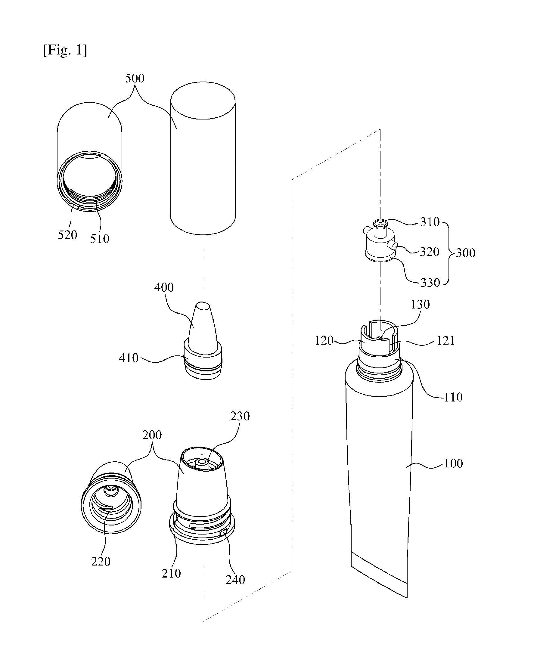
[0018] FIG. 1 is an exploded perspective view illustrating the configuration of a rotary open/close tube container according to a first embodiment of the present invention.
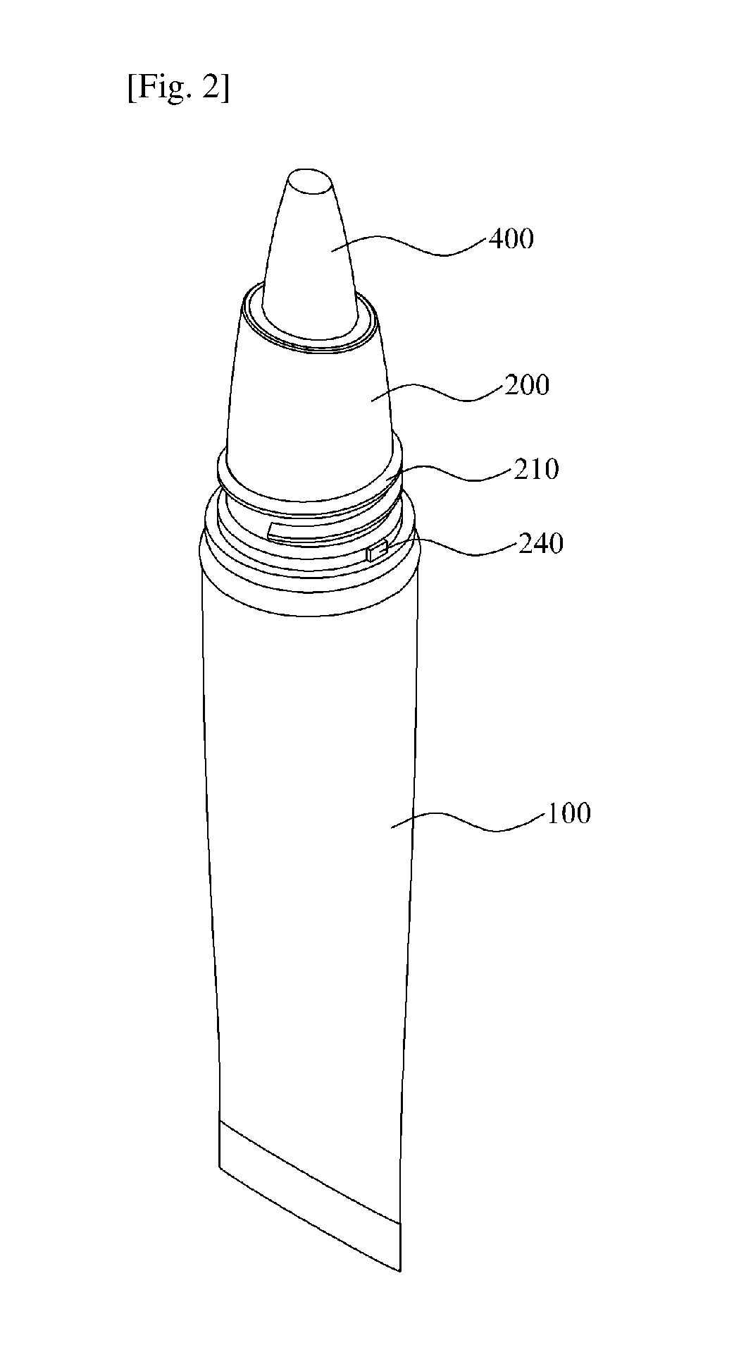
[0019] FIG. 2 is an assembled perspective view illustrating the configuration of the rotary open/close tube container according to the first embodiment of the present invention.
[0020] FIG. 3 is a cross-sectional view illustrating the configuration of the rotary open/close tube container according to the first embodiment of the present invention.
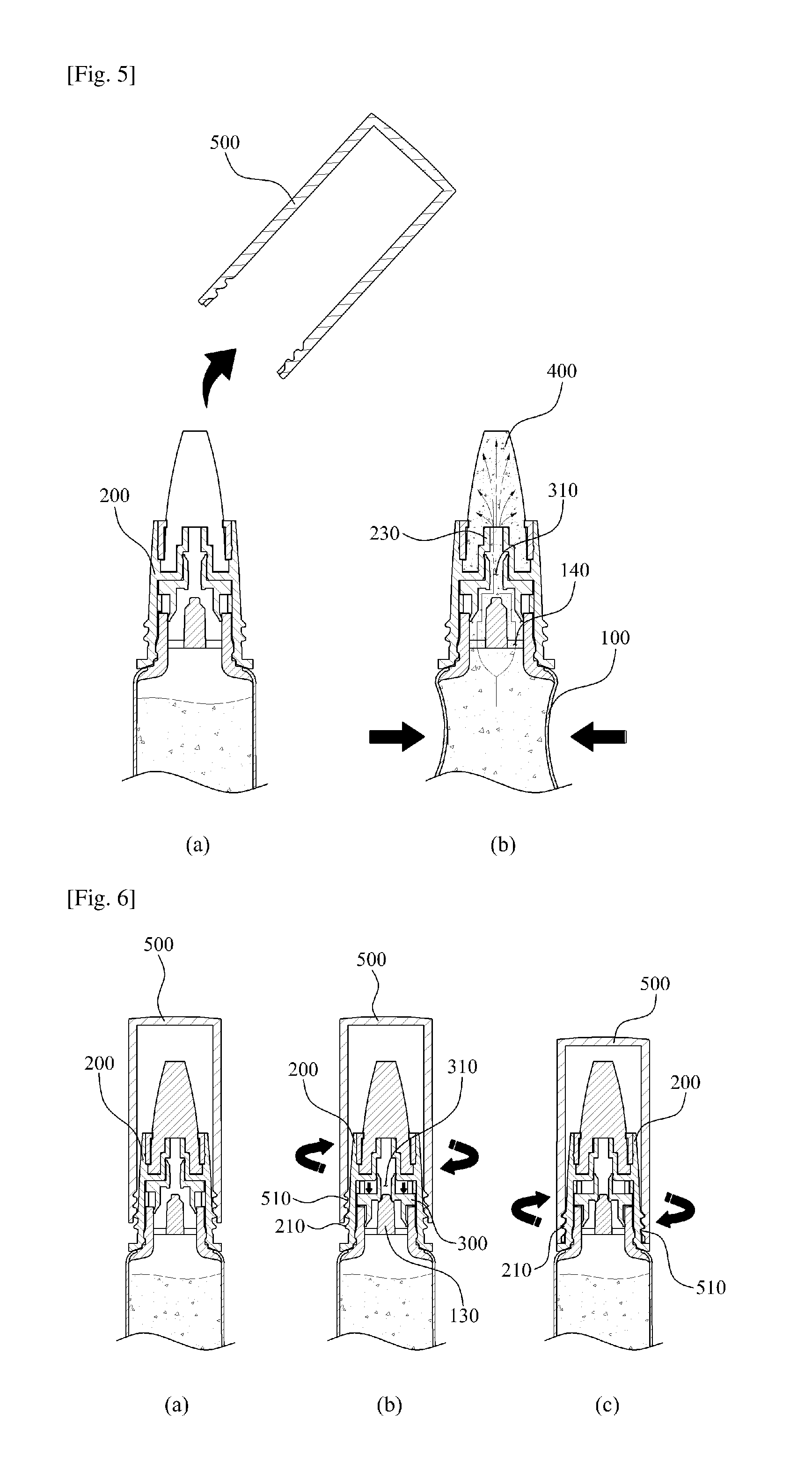
[0021] FIGS. 4 to 6 are views illustrating the usage of the rotary open/close tube container according to the first embodiment of the present invention.
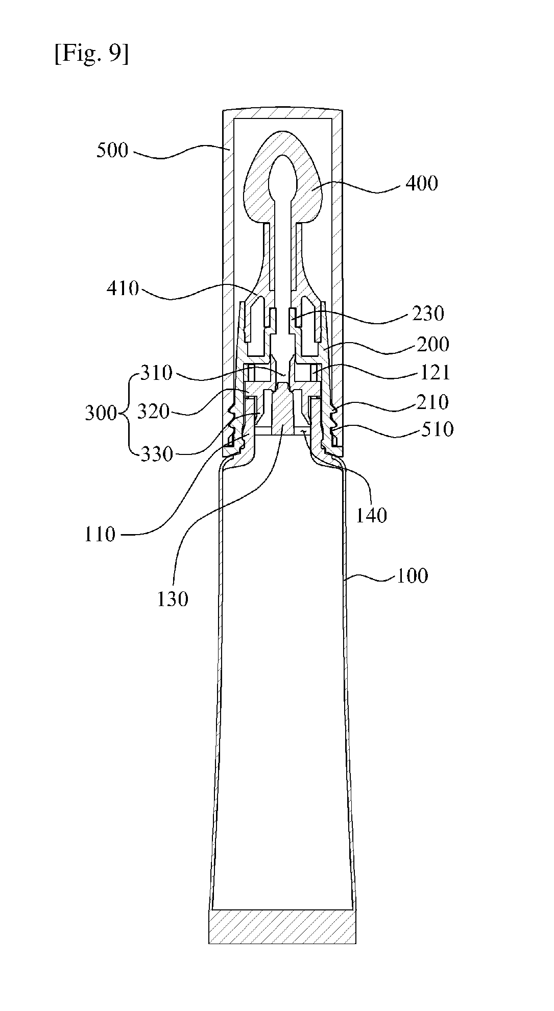
[0022] FIGS. 7 to 10 are cross-sectional views illustrating the configurations of rotary open/close tube containers according to second, third, fourth and fifth embodiments of the present invention.
DETAILED DESCRIPTION OF PREFERRED EMBODIMENTS
[0023] Hereinafter, embodiments of the present invention will be described in detail with reference to the attached drawings. The same reference numerals are used throughout the drawings to designate the same or similar components.
[0024] FIG. 1 is an exploded perspective view illustrating the configuration of a rotary open/close tube container according to a first embodiment of the present invention. FIG. 2 is an assembled perspective view illustrating the assembled configuration of the rotary open/close tube container according to the first embodiment of the present invention. FIG. 3 is a cross-sectional view illustrating the configuration of the rotary open/close tube container according to the first embodiment of the present invention.
[0025] Referring to FIGS. 1 to 3, the rotary open/close tube container according to the first embodiment of the present invention includes a container body 100, a rotating cap 200, a sealing cap 300, an applicator 400, and an over cap 500.
[0026] The container body 100 stores contents therein and has in an upper portion thereof a discharge part 110 through which the contents are discharged to the outside. The container body 100 is made of a soft tube material and changed in shape by the compressing force when a user compresses the container body 100, and thus the contents stored therein are discharged to the outside.
[0027] The present invention is characterized in that an extension part 120 extending from the discharge part 110 upwards and having a pair of perpendicular guide grooves 121 at both sides thereof is provided on the upper portion of the container body 100. Guide protrusions 320 of the sealing cap 300, which will be described later herein, are inserted into the perpendicular guide grooves 121. When the rotating cap 200 rotates, the perpendicular guide grooves 121 guide the vertical movement of the guide protrusions 320.
[0028] Furthermore, a closing protrusion 130 is provided in a central portion of the discharge part 110 and protrudes upwards from the discharge part 110 so as to open or close a content-passing hole 310 formed in the sealing cap 300. When the sealing cap 300 moves upwards, the closing protrusion 130 moves away from the content-passing hole 310 and opens the content-passing hole 310, thus allowing the contents to be discharged to the outside. When the sealing cap 300 moves downwards, the closing protrusion 130 makes close contact with a lower portion of the content-passing hole 310 and closes the content-passing hole 310, thus blocking the discharge of the contents.
[0029] A plurality of through holes 140 allowing the contents stored in the tube body 100 to pass therethrough is formed in the discharge part 110 and arranged in such a way that they enclose the closing protrusion 130.
[0030] The rotating cap 200 is rotatably coupled to the upper portion of the container body 100. A discharge hole 230 through which the contents are discharged is formed in a central portion of the rotating cap 200. A first thread 210 for threaded coupling with the over cap 500 is formed in an outer circumferential surface of the rotating cap 200.
[0031] The present invention is characterized in that a pair of spiral grooves 220 is formed at both sides of an inner circumferential surface of the rotating cap 200. The guide protrusions 320 of the sealing cap 300, which will be described later herein, are inserted into the spiral grooves 220. The spiral grooves 220 guide the guide protrusions 320 such that when the rotating cap 200 rotates in an opening direction, each guide protrusion 320 moves from a bottom dead point of the spiral grooves 220 to a top dead point thereof, and when the rotating cap 200 rotates in a closing direction, the guide protrusion 320 moves from the top dead point of the spiral groove 220 to the bottom dead point thereof. In this way, the upwards and downwards movement of the sealing cap 300 is guided.
[0032] Meanwhile, a support protrusion 240 is provided on the outer surface of the rotating cap 200 so that when the over cap 500 rotates, a rotating protrusion 520 of the over cap 500 engages with the support protrusion 240. When the over cap 500 rotates in the opening direction, the support protrusion 240 is compressed by the rotating protrusion 520, thus making it possible for the rotating cap 200 to rotate along with the over cap 500. As the rotating cap 200 rotates, the guide protrusions 320 on the sealing cap 300 move from the bottom dead point of the spiral grooves 220 to the top dead point thereof, whereby the sealing cap 300 can be moved upwards.
[0033] The sealing cap 300 is moved upwards or downwards in the rotating cap 200 by the rotation of the rotating cap 200, and forms a passage along which the contents move. The content-passing hole 310 is formed in the central portion of the sealing cap 300. The content-passing hole 310 is opened or closed by the closing protrusion 130 and provides a passage along which the contents move. The guide protrusions 320 are provided on the outer circumferential surface of the sealing cap 300. The guide protrusions 320 are inserted into the perpendicular guide grooves 121 and the spiral grooves 220 and move along the perpendicular guide grooves 121 and the spiral grooves 220.
[0034] In order to enable the contents that move through the through holes 140 to move to the content-passing hole 310 in the sealing cap 300, the sealing cap 300 preferably includes in a lower portion thereof a piston 330 which comes into close contact with an inner circumferential surface of the discharge part 110.
[0035] The applicator 400 is coupled to an upper portion of the rotating cap 200 and functions to apply contents to the skin of the user. The applicator 400 absorbs contents discharged from the discharge hole 230 and makes it possible for the contents to be applied to the skin of the user, thus providing ease of use.
[0036] An applicator support part 410 is coupled to a lower portion of the applicator 400 to make it possible for the applicator 400 to be fixed to the rotating cap 200.
[0037] The over cap 500 is threadedly coupled to the rotating cap 200 so as to be removable therefrom. A second thread 510, to be threadedly coupled with the first thread 210, is formed in an inner circumferential surface of the over cap 500.
[0038] The present invention is characterized in that when the over cap 500 is rotated in the opening direction so as to release the threaded coupling with the rotating cap 200, the over cap 500 rotates along with the rotating cap 200 throughout a predetermined section, and thereafter the over cap 500 independently rotates so that the threaded coupling with the rotating cap 200 is released. For this, the rotating protrusion 520 is provided on the inner surface of the over cap 500 so that when the over cap 500 is rotated in the opening direction to release the threaded coupling the rotating cap 200, the rotating protrusion 520 engages with the support protrusion 240, whereby the rotating cap 200 can rotate along with the over cap 500.
[0039] When the over cap 500 rotates in the opening direction, the rotating protrusion 520 pressurizes the support protrusion 240, whereby the rotating cap 200 is rotated. Here, the rotating cap 200 is rotated while the guide protrusions 320 move from the bottom dead point of the spiral grooves 220 to the top dead point thereof. If the over cap 500 rotates further after the guide protrusions 320 have been moved all the way to the top dead point of the spiral grooves 220, in other words, after the sealing cap 300 has been moved upwards and spaced apart from the closing protrusion 130 and the content-passing hole 310 has thus opened, the rotating protrusion 520 moves over the support protrusion 240, and the over cap 500 thus independently rotates. Thereby, the threaded coupling between the over cap 500 and the rotating cap 200 is released. Finally, the over cap 500 is removed from the rotating cap 200.
[0040] That is, the present invention is characterized in that, during a process of opening the over cap 500, the sealing cap 300 moves upwards and the content-passing hole 310 automatically opens first before the over cap 500 opens. After the over cap 500 has opened, there is no need for separate manipulation to open the content-passing hole 310. Therefore, the present invention can provide a user convenience.
[0041] When the over cap 500 is rotated in the closing direction, the first and second threads 210 and 510 engage with each other, whereby the rotating cap 200 is rotated. Here, the rotating cap 200 is rotated while the guide protrusions 320 move from the top dead point of the spiral grooves 220 to the bottom dead point thereof. If the over cap 500 is rotated further after the guide protrusions 320 have moved all the way to the bottom dead point of the spiral grooves 220, in other words, after the sealing cap 300 has moved downwards and come into contact with the closing protrusion 130, whereby the content-passing hole 310 is closed, the over cap 500 rotates independently. Thereby, the over cap 500 is threadedly coupled with the rotating cap 200.
[0042] In the above, the description has been made for the case where the rotating cap 200 rotates after a first and a second threads 210, 510 engage with each other when the over cap 500 rotates in the closing direction. however, possible is the configuration where, after the threaded coupling between a first and a second threads 210, 510 is first implemented according to the frictional force between the first and second threads 210, 510 and the frictional force between the guide protrusions 320 and the spiral grooves 220, the rotating cap 200 begins to rotate from the point when the rotating protrusion 520 makes contact with the support protrusion 240, and thereby the guide protrusions 320 move from the top dead point of the spiral grooves 220 to the bottom dead point thereof, so that the sealing cap 300 moves downwards.
[0043] Meanwhile, the rotating protrusion 520 of the over cap 500 moves over the support protrusion 240 from the point when the threaded coupling between the over cap 500 and the rotating cap 200 is completed, and therefore, the user can discern whether the over cap 500 has been completely coupled with the rotating cap 200 when hearing the sound that is generated at the moment that the rotating protrusion 520 moves over the support protrusion 240.
[0044] As shown in FIGS. 7 to 10, rotary open/close tube containers according to second, third, fourth and fifth embodiments of the present invention can employ various applicators 400, such as a brush, a silicon member, a puff, an applicator for lipstick, and an applicator for mascara. In the case where the applicator 400 is an applicator for mascara, a wiper 530 may be preferably provided at the over cap 500 so that when the over cap 500 is removed, some contents still clinging to a mascara brush can be wiped out therefrom.
[0045] The functions and configurations of the other components are the same as those of the first embodiment of the present invention; therefore, a detailed explanation thereof will be omitted.
[0046] Hereinafter, the operation of the rotary open/close tube container according to the first embodiment of the present invention will be described with reference to FIGS. 4 to 6. FIGS. 4 to 6 are views illustrating the usage of the rotary open/close tube container according to the first embodiment of the present invention.
[0047] Referring to FIGS. 4 to 6, in the rotary open/close tube container according to the first embodiment of the present invention, in the state in which the over cap 500 is threadedly coupled to the rotating cap 200, the content-passing hole 310 is closed by the closing protrusion 130. In this state, when the over cap 50 is rotated in the opening direction, the rotating protrusion 52 pressurizes the support protrusion 240 of the rotating cap 200, whereby the rotating cap 20 is rotated along with the over cap 500.
[0048] In this way, when the rotating cap 200 is rotated, the guide protrusions 320 of the sealing cap 300 move from the bottom dead point of the spiral grooves 220 to the top dead point. Thereby, the sealing cap 300 moves upwards away from the closing protrusion 130. Consequently, the content-passing hole 310 is opened.
[0049] From the points at which the guide protrusions 320 have moved all the way to the top dead point of the spiral grooves 220 and come into contact with the other end of the spiral grooves 220, the rotating cap 200 no longer rotates. At this moment, if the over cap 500 rotates further, the rotating protrusion 520 moves over the support protrusion 240, and the over cap 500 independently rotates, whereby the threaded coupling between the over cap 500 and the rotating cap 200 is released, and thus the over cap 500 is removed from the rotating cap 200.
[0050] After the over cap 500 has been removed from the rotating cap 200 through the above-mentioned process, the content-passing hole 310 is in an open state. In this state, when the container body 100 is compressed, the contents stored in the container body 100 pass through the through holes 140, move to the content-passing hole 310, and are then discharged to the applicator 400 through the discharge hole 230, thus making it possible for the user to apply the contents to his/her skin using the applicator 400.
[0051] Subsequently, after the use of the contents has been completed, the over cap 500 is rotated in the closing direction and threadedly coupled to the rotating cap 200. When the over cap 500 rotates in the closing direction, the first and second threads 210 and 510 engage with each other and thus the rotating cap 200 rotates.
[0052] As such, when the rotating cap 200 rotates, the guide protrusions 320 of the sealing cap 300 move from the top dead point of the spiral grooves 220 to the bottom dead point. Thereby, the sealing cap 300 moves downwards and comes into contact with the closing protrusion 130. Consequently, the content-passing hole 310 is closed.
[0053] After the guide protrusions 320 have moved all the way to the bottom dead point of the spiral grooves 220 and come into contact with first ends of the spiral grooves 220, the rotating cap 200 no longer rotates. Thereafter, if the over cap 500 is rotated further, the over cap 500 independently rotates, and the over cap 500 is threadedly coupled to the rotating cap 200.
[0054] As described above, the present invention is configured such that, during the process of opening or closing the over cap 500, the sealing cap 300 moves upwards or downwards and thus the content-passing hole 310 first opens before the over cap 500 is opened or closed. Therefore, not only can the present invention prevent a problem of leakage of contents which may be caused when the user carelessly closes the over cap 500 with the content-passing hole 310 open, but also, no separate manipulation is required to open the content-passing hole 310 after the over cap 500 is opened, thus providing a.
[0055] As the present invention may be embodied in several forms without departing from the spirit or essential characteristics thereof, it should also be understood that the above-described examples are not limited by any of the details of the foregoing description, unless otherwise specified, but rather should be construed broadly within its spirit and scope as defined in the appended claims, and therefore all changes and modifications that fall within the meets and bounds of the claims, or equivalences of such meets and bounds are therefore intended to be embraced by the appended claims.
* * * * *
D00000
D00001
D00002
D00003
D00004
D00005
D00006
D00007
D00008
D00009
XML
uspto.report is an independent third-party trademark research tool that is not affiliated, endorsed, or sponsored by the United States Patent and Trademark Office (USPTO) or any other governmental organization. The information provided by uspto.report is based on publicly available data at the time of writing and is intended for informational purposes only.
While we strive to provide accurate and up-to-date information, we do not guarantee the accuracy, completeness, reliability, or suitability of the information displayed on this site. The use of this site is at your own risk. Any reliance you place on such information is therefore strictly at your own risk.
All official trademark data, including owner information, should be verified by visiting the official USPTO website at www.uspto.gov. This site is not intended to replace professional legal advice and should not be used as a substitute for consulting with a legal professional who is knowledgeable about trademark law.