Felton flyer
Fell; William P.
U.S. patent application number 14/545842 was filed with the patent office on 2016-12-29 for felton flyer. The applicant listed for this patent is William P. Fell. Invention is credited to William P. Fell.
| Application Number | 20160375975 14/545842 |
| Document ID | / |
| Family ID | 57600955 |
| Filed Date | 2016-12-29 |
| United States Patent Application | 20160375975 |
| Kind Code | A1 |
| Fell; William P. | December 29, 2016 |
Felton flyer
Abstract
An electronic Control system for controlling a water vessel in regards to its propulsion, and thrust vectors and its steering. A helm wheel that has an electronic output that governs the steerage of a water vessel. The control system determines the reactive speed and number of turns needed to accomplish a given turn, this pre-selected speed and distance traveled gives the rudder two different sets of parameters for full rotation of the Helm wheel from full rudder to the Port to full rudder to the starboard The rudder or outboard motor has a sensor that gives the control system information by way of a variable voltage as to its direction and where the rudder is parked. The steering actuator has a dual motor set up that supply's enough power and torque to control the steering cable and slide bar of three outboard engines. The Control system's other input is a joystick controller, its output governs the direction of the propulsion of the watercraft in either a forward direction or Aft or reverse direction and in the same movement the throttle will ramp up in rpm's proportionately. The operators movement of the joystick controller determines this control command. The joystick in its y-axis has built in friction forces that enable it to stay where the operator moves it.
| Inventors: | Fell; William P.; (Anchorage, AK) | ||||||||||
| Applicant: |
|
||||||||||
|---|---|---|---|---|---|---|---|---|---|---|---|
| Family ID: | 57600955 | ||||||||||
| Appl. No.: | 14/545842 | ||||||||||
| Filed: | June 27, 2015 |
| Current U.S. Class: | 440/1 |
| Current CPC Class: | B63H 25/02 20130101; B63H 2025/022 20130101; B63H 20/12 20130101; B63H 21/21 20130101; B63H 21/22 20130101; B63H 2025/026 20130101; B63H 2021/216 20130101 |
| International Class: | B63H 21/21 20060101 B63H021/21; B63H 20/34 20060101 B63H020/34; B63H 25/02 20060101 B63H025/02; B63H 25/38 20060101 B63H025/38; B63H 21/22 20060101 B63H021/22; B63H 20/12 20060101 B63H020/12 |
Claims
1. A boat of the type driven by a propeller propulsion system. a outboard drive with a propeller Producing propulsion to move the boat forward or in a reverse fashion, the motor acts as a rudder directing a flow of water generally along the longitudinal axis of the boat, the rudder or outboard motor being capable to rotation about generally vertical axis to provide left and right sideward forces on the boat, and A transmission shift and throttle levers for engaging the transmission in its forward or it reverse gear, and a lever for increasing or decreasing the throttle. A helm wheel that is rotated to its full right and to its full left having as its mechanical mover a clutch disc, that has an applied force internally to the wheels center support shaft, thus allowing the feel of forces that would naturally be felt if the wheels mechanical output were causing effectors to move a rudder or an outboard engine. The output of this mechanical shaft is coupled to a potentiometer and use as a voltage divider. A rudder position sensor connected to the rudder and affixed to drive mechanism. So that full travel of the rudder will be proportionate to the sensors full travel.
2. a boat from claim 1 further comprising a joystick control member connected electrically to the electrical control circuit, the stick control member having a neutral position, at least one forward position, and at least one reverse position, and the electrical circuit and position sensor being configured so that when the stick control member is placed in the neutral position the drive mechanism moves the transmissions to their respective neutral position and the throttle to their respective idle positions.
3. The boat of claim 2 wherein the stick control member has a friction force applied to the mechanism that arrest the movement whenever the operator lets goes of it, in the Y-axis.
4. The boat of claim 2 or 3 further comprising a rudder or an outboard motor mechanism connected to the rudder and electrically controlled by the electrical control circuit, wherein the helm wheel control member of claim 1 is configured to rotate about a generally vertical axis, and wherein the electrical control circuitry and rudder drive mechanism are configured so that rotation of the helm wheel produces rotation of the rudder or an outboard motor and sideward forces on the boat.
5. the boat of claim 1 further comprising of a drive mechanism that when controlled by the electrical control circuit of claim 1 produces forces to effect the movement of a mechanical cable drive assembly whose output is connected to a rudder or an outboard motor that has a rotation full left or full right rudder. This mechanical drive mechanism of claim 4 employs two dc electric high efficient motors whose output shafts are fitted with sprockets and they are coupled together by a 1/2 inch chain assembly thus a combined horsepower for usable power. The mechanical drive produces enough force to effect the movement of several rudders or outboards of various sizes.
6. The boat of claim 1 wherein the helm wheel has a mechanical rotation of approximately three quarter turns to its full right rotation from its center and three quarter rotation turns to its full left from its center of rotation position.
7. The boat of claim 1 wherein the electrical control circuit of claim 2 determines the lock to lock circuitry output, this effects the helm wheels mechanical turns compared to the actual movement the rudder or outboard motor of claims 1 & 5. This two stage circuit has employed two different sets of adjustable parameters that determine the range of actual travel of the rudder or outboard motor compared to the actual distance traveled by the turning of the helm wheel from full right rudder to full left rudder or full turns of the helm wheel from full right to full left turn. as seen in FIG. 1 35,36,37,38 This lock to lock configuration has two selectable and adjustable parameters that change the ratio of the turning ratio of the helm wheel compared to the actual distance traveled by the rudder or outboard. The turning of the helm wheel of claim 1 will be followed by a direct response of the electrical control circuitry it then gives the command to the mechanical drive mechanism of claim 5 that will proportionally follow its lead.
8. the boat of claim 1 further comprising of an electrical control circuit that controls all functions of the total system and accepts inputs from the joystick of claim 2 and helm wheel electronic output of claim 1. An external feedback sensor is also fed into the control circuit. This electrical control circuit is that of analog circuitry, consisting of analog logic circuitry that facilitates its decision making device.
9. the boat of claim 1or 2 wherein the mechanical drive mechanism of claim 5 has employed a feedback sensor of the potentiometer type and it is used as a voltage divider to signal to the electrical control circuitry of claim 8 the exact position of the rudder or outboard motor in its respective travel.
10. The boat of claim 1 further comprising of a standard cable steering transmission that is coupled to the mechanical drive mechanism of claim 4, 7, 8 So that the total horsepower of the drive unit can be utilized to drive the cable transmission, that will drive the mechanical cable actuator that is attached to the rudder or outboard motor assembly.
11. the boat of claims 1 & 2 further comprising of a dc actuator that is connected to the electrical control circuit of claim 8, this dc actuator follows the command of the Joystick controller of claim 2 and provides mechanical cable outputs that drive the shift and throttle of the outboard or inboard motors.
12. The boat of claim 1 is further comprising of a single axis joystick fitted with a potentiometer that is used as a voltage divider to supply a command signal to the electrical control circuit of claim 8 the output of the electrical control circuit is directly connected the dc actuator of claim 11 to effect the movements of both the throttle and shift of an outboard motor or an inboard motor and transmission by way of the dc actuators mechanical cable for throttle and its mechanical cable for shift.
13. the boat of claim 1, 2, 3 further comprising of a auxiliary input port in to the electrical control circuit of claim 8 this input port has at its jack pins that allow access to inputs to the mode switching circuitry and to logic circuitry of claim 8 that both effect the steering and throttle and shift circuitry.
14. the boat of claim 1, 2, 8, 13 wherein the auxiliary input port of claim 13 is an access port to the control circuitry of claim 8&13 a hand held control device which contains mode switching button switches and a knob wheel type that serves as the function of helm wheel while plugged in to the port of claim 13, and a slider control to serve as the function of the joystick, these two controls while plugged in to the auxiliary input port will control the boat in the same fashion of claim 1, 2, 12, whereas the operator can drive the boat with full control from anywhere aboard the vessel or on shore as docking the vessel. This hand held device carries out its commands by an umbilical cord cable with a connector at its end or by a wireless connection into both can be plugged into the port of claim 13.
15. The boat of claim 1 further comprising of the hand held control devise of claim 14 that upon it being plugged in sends a signal to the electrical controller circuit of claim 8 to disable the control station and all functions of the joystick of claim 12 and the helm wheel of claims 1 & 7 and enable the hand held control device for total control.
16. a boat of the type driven by a propeller such as an outboard or inboard motor comprising A helm wheel for steering the rudder or outboard and directing the flow of water generally along the longitudinal axis of the boat, the rudder or outboard motor being capable of rotation about a generally vertical axis to provide left and right sideward forces to the boat and A joystick controls the throttle and shift. A control panel, comprising of switches that will switch modes and hold the joystick. An electrical control circuit, that and carries out all control commands. A mechanical drive mechanism that delivers high torque power to the rotation of the rudder or outboard motor. A hand held control device that will control the vessel remotely.
17. The boat of claim 1 & 2 wherein this system controls the steering, throttle, shift of any outboard or inboard propulsion systems including any outboard conversion to jet propulsion, its nozzle and deflector thrust assemblies. Utilizing the drive unit of claim 5, 7, 11 to facilitate this type of control to a converted outboard drive assembly to that of a Jet propulsion assembly. The nozzle and deflector of this conversion assembly is controlled by the mechanical drive mechanism and the dc actuator.
Description
TECHNICAL FIELD
[0001] This invention relates to an apparatus for controlling a watercraft utilizing a helm wheel and a feed back sensor for proportional steering control of the vessel and a joystick to control the throttle and shift.
BACKGROUND OF THE INVENTION
[0002] Many aspects of this invention relate in general to the control of throttle and transmission shifting, steering of a water vessel as controlled power movers and more particularly to comprehensively system and methods for providing the operator with linear movement and control of the vessel.
[0003] Many boat operators have controlled their watercraft by using a devise such as a steering wheel. Likewise many boat operators have controlled their watercraft by means of a control lever to affect the shift and throttle of their engines.
[0004] These types of control levers and wheels have been used for great many years and are still an effective means for control today.
[0005] Many powered movers use proportional speed controls in the form of a joystick or an equivalent type of lever or knob that controls an actuator or actuators to do the work of powered moving. Actuators are often Hydraulic and can be that of other form such as pneumatic, Electro-magnetic, or some combination thereof.
[0006] For those skilled in the art of operating watercraft or sea going vessels it is well known that tight control from lever to the end mover or powered mover is desirable in order to maintain control of the vessel in all types of seas or conditions.
[0007] Many of the above mentioned types of controls have problems with linkage being slack and a lack precision steering thus causing the vessel operator to steer erratically or over steer.
[0008] In the field of shifting and throttle control, it has also been noted that by utilizing the aforementioned means to effect shifting and throttle, some problems such as the fluctuation of the joystick or lever used as a control medium exist.
[0009] This is particularly a problem when the vessel is in high seas or is experiencing the effects of wave action or in high current rivers such as in the Alaskan wilderness where fast and accurate steerage is critical to avoid protruding rocks.
[0010] The vessel tends to bounce and move about, when this happens the operator transfers this movement to the lever or joystick that he is using to control the vessel thus the results are erratic control of the vessel.
[0011] In this kind of environment the operator often lacks a place to secure himself while in control. Movers such as hydraulic rams to affect the steering or rudder of a given vessel are very powerful as they produce thousands of pounds of force.
[0012] Other Movers such as motorized chain or cable actuators or drives however often lack sufficient power needed to move large rudders or multiple outboard engines at the same time.
[0013] A sizable unmet need has been revealed in relation to optimizing such movements particularly in the interest of enhanced control of steering and shift and throttle on all types of vessels.
[0014] Related needs include the goal to minimize unnecessary cost and complexity, to enhance the ease of use.
[0015] It is an object of the present invention to address these and other needs presented by the prior art.
[0016] Known feedback technology has helped but more has been long needed.
[0017] Very few applicants have the combination of control devises such as electronic two speed and two turn ratio of helm wheel and a joystick for integrating full control of throttle and shift, thus having a true "Fly by wire" control system. U.S. Pat. No. 7,354,321 Takada, Hideaki of Wako Japan #B63/84 International, US #440/84 Richard T Novey
[0018] U.S. Pat. No. 1,2315,828 William P Fell
[0019] U.S. Pat. No. 6,942,531 William P Fell
SUMMARY OF THE INVENTION
[0020] The present invention (known as the Felton Flyer) is just the answer for many unmet needs that have plagued the prior art--aspects of the invention allowing precise yet smooth operation of steering and that of throttle and shift control that is intuitively interpreted and adjusted by the operator.
[0021] This system presented is a true (Fly by wire) all electronic steering and shift and throttle control system that utilizes the vessel steering cable drive instrument as a means and point of interface for steering control thus eliminating bulky and cumbersome actuator placement at the stem of the vessel.
[0022] The system is equipped with a powerful two motor synchronized drive actuator that had the ability to drive the motors or rudders of up to three sizable outboards or rudders.
[0023] It also combines throttle and shift of outboard engines with one deflection either in forward movement or reverse movement of an electronic Joystick that has been fitted with a friction stopping device to ensure the joystick will stay in place where the operator left it.
[0024] With this configuration of controls, it allows full control of the vessel in harsh conditions and in high speed operating.
[0025] The two function steering has a quick switch that allows the operator to change the parameters of helm wheel steering in an instant from slow course correction to fast course correction in dangerous conditions such as avoiding partially submerged rocks at hi speeds.
[0026] This system controls the steering, throttle, shift of any outboard or inboard propulsion systems including any outboard conversion to jet propulsion, its nozzle and deflector thrust assemblies.
[0027] The following circuit and its description have been developed to facilitate a switchable two stage steering Apparatus utilizing an electronic Helm Wheel.
[0028] The Steering wheel will operate the same as in a manual steering wheel system in that if the operator turned the wheel to the right or in this application to Starboard the vessels rudder or if an outboard will move the engine towards the right or starboard direction to accomplish the turn.
[0029] If turning the steering wheel to the Left or to the port direction the rudder or engine will move towards the Left or starboard direction to accomplish the turn. The (Two Stage Circuit) allows the command given by the electric helm wheel to determine its direction and the distance it is to travel.
[0030] In Stage one primarily used in slow speed or docking applications set the distance and speed the rudder will travel. For an example if the steering wheel is deflected to full right rudder the 1.sup.st stage limits the turning radius to an adjustable degree of 1/4 turn to (full right rudder) from its center position. If turning the wheel to full left rudder it will do so in 1/4 turn from its center position.
[0031] The second stage if engaged will allow the turning the steering wheel from its center position to full left rudder 3/4 turn of the wheel.
[0032] The full turning radius of stage one could be known as having a turning radius as 1/2 turn form (lock to lock).
[0033] The second stage could be known as having a turning radius as one turn and a half (lock to lock)
[0034] The switching from stage one to stage two and vice versa will be accomplished via a push button affixed to the dash.
[0035] This system will allow the safe turning of the wheel at high speed so as to not endanger persons or turn over the vessel if deflected at a fast rate.
[0036] It will also allow the operator to at slow speeds to have a much shorter turning radius when needed such as in a tight slip or while docking the craft.
[0037] The following description is of the shift and throttle operation commanded by a single axis electronic Joystick controller.
[0038] The Joysticks Y-axis has a detent that allows it to be unmistakably in it neutral position or it center of throw. Thus the potentiometer will in like manner be in its center or mid value.
[0039] When the system is on and in its drive mode and the joystick is in its center detent, the system will remain in its neutral transmission mode on the outboard or inboard drives and the throttle or throttles will remain in their respective idle Rpm's.
[0040] If the joystick is deflected forward fifteen degrees then the forward shift will engage, if the joystick is deflected further for every degree of movement the throttle will increase from its idle Rpm to higher Rpm's as desired.
[0041] If the joystick is deflected aft or its reverse the same will result with the exception of the reverse gear will now be in engaged. it will be noted that the throttle has an adjustable level limit for the throttle Rpm, this is to ensure that full throttle will not be available in the reverse gears.
[0042] The control circuit for shift and throttle has a built in adjustable window for shift pause, this is added to ensure that if in the forward gear and the operator pulls back on the joystick too quickly and it goes past its neutral detent or neutral transmission, the reversing gear will not engage until the sufficient time that has been set for pausing has elapsed.
[0043] This feature will help prevent drive shafts from being snapped and drive gears from becoming stripped.
[0044] The built in friction force on the joystick keeps the joystick in the position that the operator last left it, this feature enables the operator to concentrate on steering and navigating while underway.
BRIEF DESCRIPTION OF THE DRAWINGS
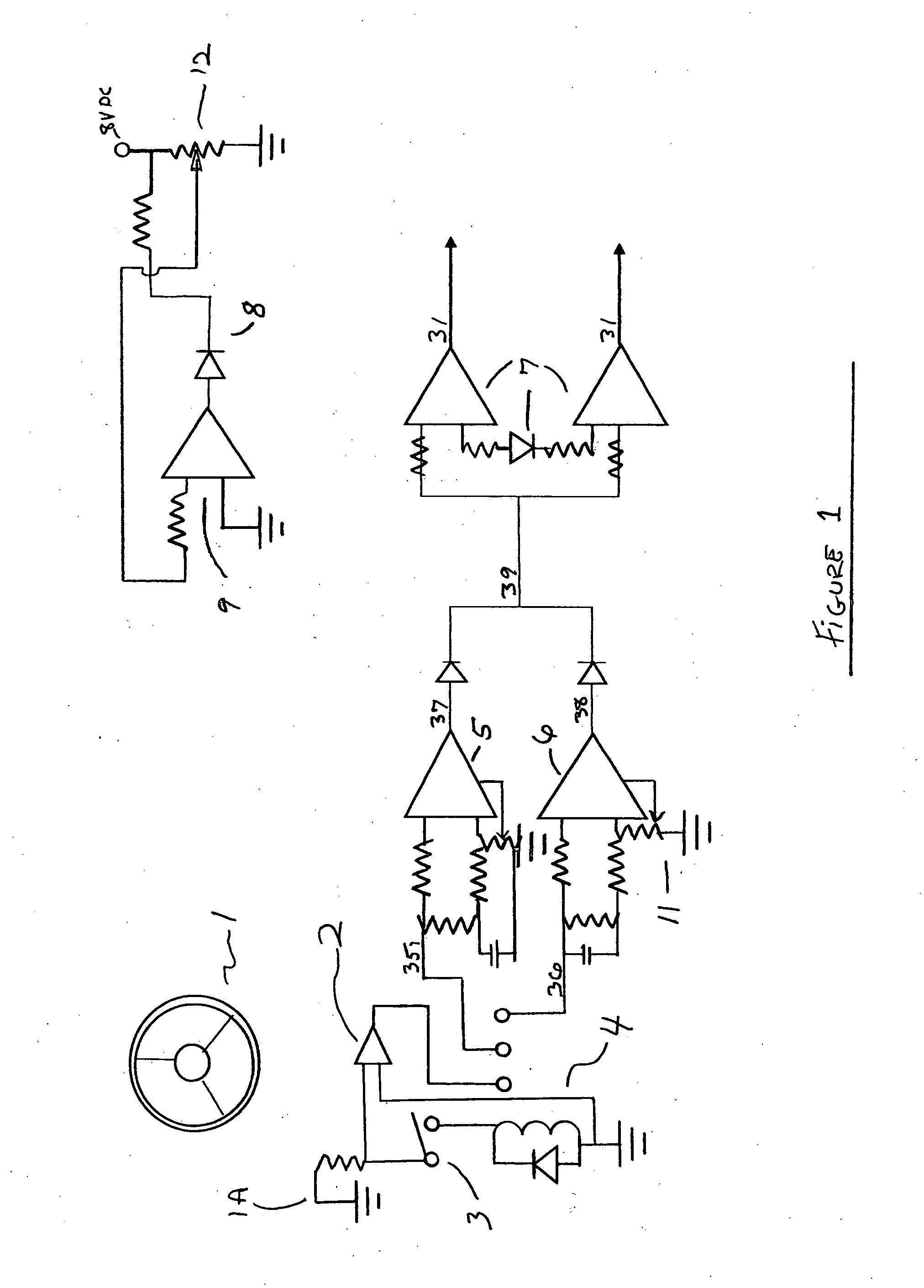
[0045] (1) FIG. 1 Shows circuit schematics of the two stage steering and its parameters.
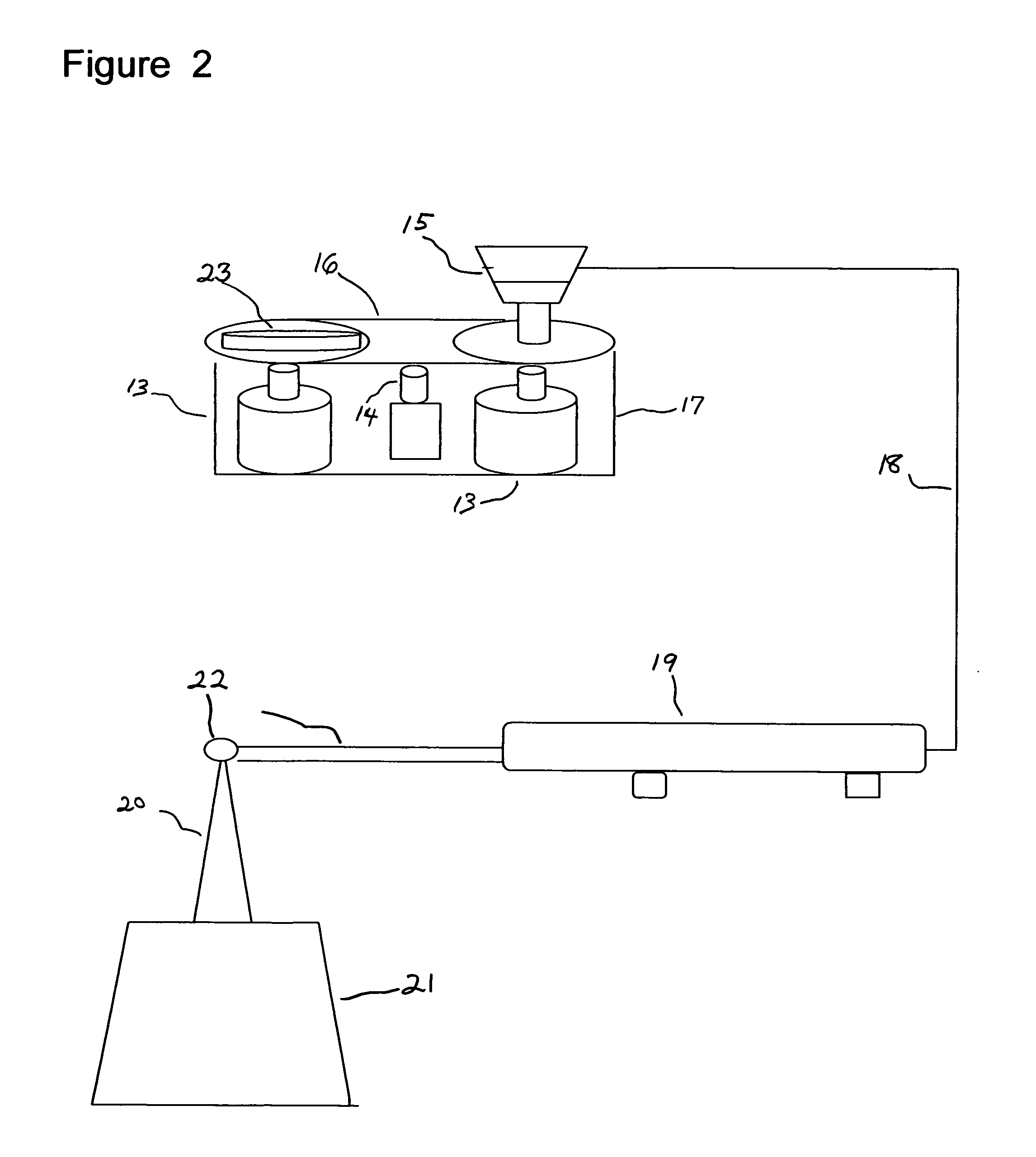
[0046] (2) FIG. 2 shows the DC Actuator assembly and end ram effector.
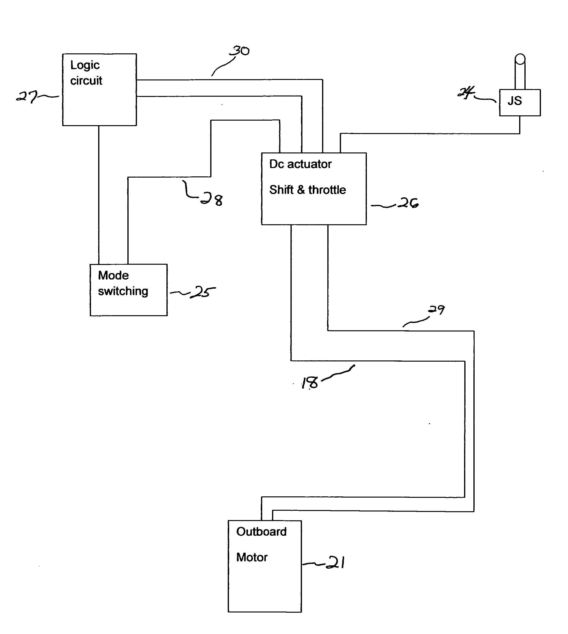
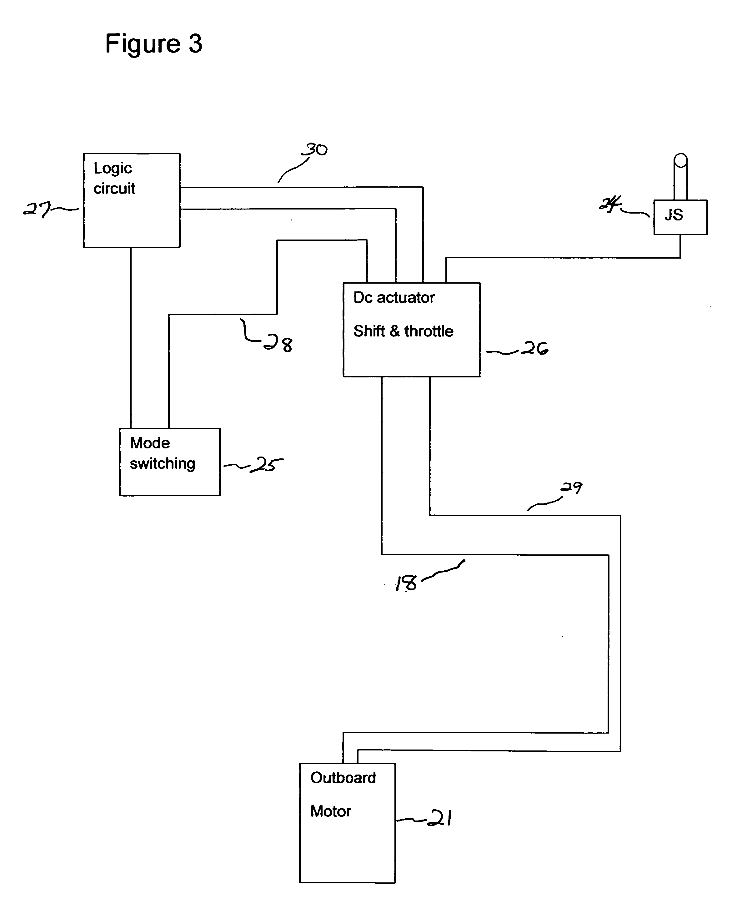
[0047] (3) FIG. 3 shows Block diagram of component layout.
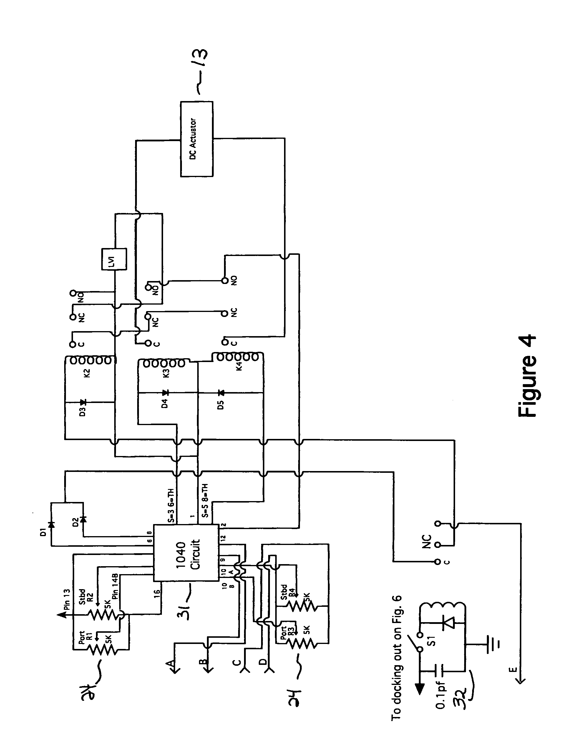
[0048] (4) FIG. 4 shows a schematic of the steering circuit and drivers.
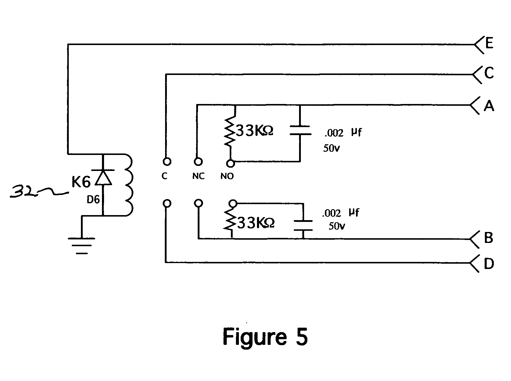
[0049] (5) FIG. 5 shows a schematic of a sensitivity circuit for steering input.
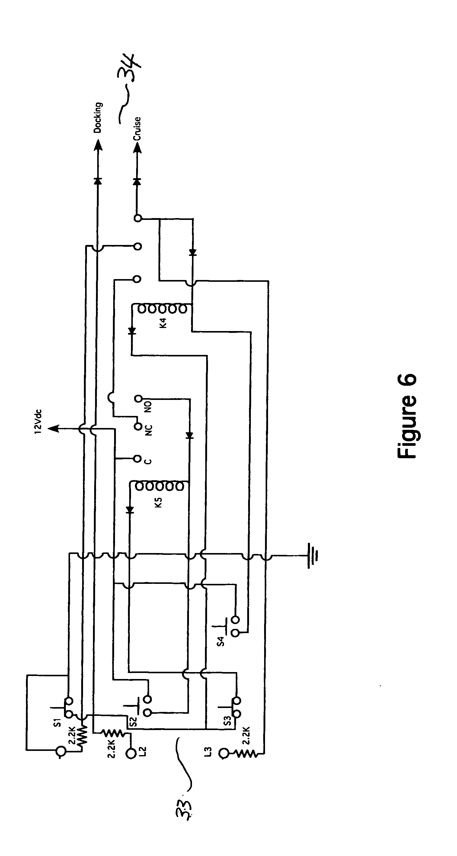
[0050] (6) FIG. 6 shows a schematic of the mode switching circuit.
DETAILED DESCRIPTION OF THE PREFERRED EMBODIMENT
[0051] The following circuit and its description have been developed to facilitate a switchable two stage steering Apparatus utilizing an electronic Helm Wheel.
[0052] The Steering wheel will operate the same as in a manual steering wheel system shown in FIG. 1 (1) in that if the operator turned the wheel to the right or in this application to Starboard the vessels rudder or if an outboard will move the engine towards the right or starboard direction to accomplish the turn.
[0053] If turning the steering wheel to the Left or to the port direction the rudder or engine will move towards the Left or starboard direction to accomplish the turn. The (Two Stage Circuit) shown in FIG. 1 (2 thru 6) allows the command given by the electric helm wheel shown in fig (a) to determine its direction and the distance it is to travel.
[0054] In Stage one shown in FIG. 1 (10&11) is a R/C pad followed by an amplifier shown in FIG. 1 (5&6) of a gain no less than 20 and no higher than 200 and is primarily used in slow speed or docking applications which set's the distance and speed the rudder will travel.
[0055] For an example if the steering wheel is deflected to full right rudder the 1.sup.st stage limits the turning radius shown in FIG. 1 (5) to an adjustable degree of 1/4 turn to (full right rudder) from its center position. If turning the wheel to full left rudder it will do so in 1/4 turn from its center position.
[0056] The second stage shown in FIG. 1 (12& 6) if engaged will allow the turning the steering wheel from its center position to full left rudder 3/4 turn of the wheel. The signals are then sent to the Driver portion of the circuit shown in FIG. 1 (7) which in turn will then by its outputs drive the high power devices (not shown) to effect the Hydraulics and or electric motors.
[0057] The driver circuitry has two inputs, FIG. 1 (5) serves as the Master an FIG. 1 (6) serves as the slave or the reference signal shown in FIG. 1 (12) and is conditioned by a buffer amplifier shown in fig (9).
[0058] The full turning radius of stage one could be known as having a turning radius as 1/2 A turn form (lock to lock).
[0059] The second stage could be known as having a turning radius as one turn and a half (lock to lock)
[0060] The switching from stage one to stage two and vice versa will be accomplished via a push button affixed to the dash shown in FIG. 1 (3) the push button then turns on the circuit relay shown in FIG. 1 (4) which selects the stage desired.
[0061] This system will allow the safe turning of the wheel at high speed so as to not endanger persons or turn over the vessel if deflected at a fast rate.
[0062] It will also allow the operator to at slow speeds to have a much shorter turning radius when needed such as in a tight slip or while docking the craft.
[0063] The Helm steering wheel in FIG. 1 (1) has an electronic voltage divider circuit that converts mechanical movement of the helm wheel to a variable voltage output FIG. 1 (1a). This output is buffered by an amplifier FIG. 1 (2), the output of this amplifier is then fed into a selector relay circuit FIG. 1 (4).
[0064] The switching circuit shown in FIG. 6 (34) controls this selector relay.
[0065] The selector switch has two outputs FIG. 1 (35&36).
[0066] In the normally relaxed mode or relay FIG. 1 (4) the input to the lock to lock amplifier FIG. 1 (5) is selected which has at its input stage fixed parameters to allow a wide window of travel for the helm wheels processed output FIG. 1 (37).
[0067] If the relay FIG. 1 (4) is energized by the mode switching circuit FIG. 6 (34) the normally open output will be connected to the input circuitry FIG. 1 (36) of amplifier FIG. 1 (6). This amplifier also has fixed parameters that allow a narrow window of travel for the helm wheels processed output FIG. 1 (38)
[0068] These outputs are combined FIG. 1 (39) and are fed into the output driver circuit FIG. 1 (7) & displayed in FIG. 4 (32e) The steering circuit FIG. 4 (31) has a reference sensor FIG. 1 (12) & FIG. 2 (14) this output is a voltage divider, this variable. Signal is then fed into a buffer amplifier FIG. 1 (9) the output of this amplifier is then protected FIG. 1 (8) and fed into the driver circuit FIG. 1 (7)
[0069] The dc actuator FIG. 2 (17) is an electromechanical drive system that has two-dc motors FIG. 2 (13) in tandem connected by a 1/2 inch drive chain, FIG. 2 (16)
[0070] The combined mechanical output is coupled to a 1/2 inch cable transmission FIG. 2 (15) the cable transmission drives the steering cable FIG. 2 (18), the steering cable is directly connected to a mechanical actuator FIG. 2 (19), the Mechanical actuator has its output shaft FIG. 2 (22) coupled to the tiller arm of an outboard or if inboard the rudder.
[0071] The component layout of the system is shown in FIG. 3, the logic circuit FIG. 3 (27), and gives control commands to the dc actuators FIG. 3 (26) & FIG. 2 (17)
[0072] FIG. 4 signals a, b, c, d, and relay control lead are connected to FIG. 5 relay for sensitivity of the steering circuit shown in FIG. 4, the relay coil FIG. 4 (32) is connected to docking output FIG. 6 (34).
* * * * *
D00000
D00001
D00002
D00003
D00004
D00005
D00006
XML
uspto.report is an independent third-party trademark research tool that is not affiliated, endorsed, or sponsored by the United States Patent and Trademark Office (USPTO) or any other governmental organization. The information provided by uspto.report is based on publicly available data at the time of writing and is intended for informational purposes only.
While we strive to provide accurate and up-to-date information, we do not guarantee the accuracy, completeness, reliability, or suitability of the information displayed on this site. The use of this site is at your own risk. Any reliance you place on such information is therefore strictly at your own risk.
All official trademark data, including owner information, should be verified by visiting the official USPTO website at www.uspto.gov. This site is not intended to replace professional legal advice and should not be used as a substitute for consulting with a legal professional who is knowledgeable about trademark law.