Multihull Watercraft
Salani; Steven John
U.S. patent application number 14/752673 was filed with the patent office on 2016-12-29 for multihull watercraft. The applicant listed for this patent is Steven John Salani. Invention is credited to Steven John Salani.
| Application Number | 20160375971 14/752673 |
| Document ID | / |
| Family ID | 57600967 |
| Filed Date | 2016-12-29 |


View All Diagrams
| United States Patent Application | 20160375971 |
| Kind Code | A1 |
| Salani; Steven John | December 29, 2016 |
Multihull Watercraft
Abstract
The patent discloses a multihull watercraft with a unique hull configuration providing numerous benefits. By relocating the passenger cabins from the float hulls to the upper hull, the accommodation space and the float hulls may be independently optimized. The new configuration also provides reduced windage, and creates additional deck space for easier boarding, recreational use, and safer access to shore craft. A new sailing rig is also disclosed that is easier to operate and maintain than the conventional Bermuda rig. The entire rig can be rotated with a single winch or control wheel to achieve the optimum angle of attack into the wind.
| Inventors: | Salani; Steven John; (El Segundo, CA) | ||||||||||
| Applicant: |
|
||||||||||
|---|---|---|---|---|---|---|---|---|---|---|---|
| Family ID: | 57600967 | ||||||||||
| Appl. No.: | 14/752673 | ||||||||||
| Filed: | June 26, 2015 |
| Current U.S. Class: | 114/61.2 ; 114/102.19 |
| Current CPC Class: | B63B 1/10 20130101; B63B 27/36 20130101; B63B 15/0083 20130101; B63B 2035/004 20130101; B63H 9/1021 20130101; B63B 23/02 20130101; B63B 1/121 20130101; B63B 2035/009 20130101; B63H 9/08 20130101; B63H 2009/088 20130101; B63B 29/00 20130101 |
| International Class: | B63H 9/08 20060101 B63H009/08; B63B 3/38 20060101 B63B003/38; B63B 29/02 20060101 B63B029/02 |
Claims
1. A multihull watercraft including left and right parallel float hulls, an upper hull bridging the space between said float hulls, and four support structures connecting between the upper hull and the left and right float hulls, wherein the improvement comprises the relocation of the passenger cabins from within the float hulls to the forward and aft regions of the upper hull, thereby permitting hydrodynamically efficient narrow float hulls, and wherein said forward and aft upper hull regions extend laterally to positions beyond the longitudinal centerlines of the left and right float hulls thereby maximizing the cabin space, and wherein the middle portion of said upper hull containing the common area is constrained laterally to a region inboard of the longitudinal centerlines of the left and right float hulls, thereby creating space for deck areas on top of the left and right float hulls for the purpose of easier boarding, for recreation, and for safer and easier boarding of shore craft.
2. The multihull watercraft of claim 1 wherein each support structure is comprised of 2 or more narrow beams that allow lateral flow of air thereby reducing windage on the watercraft.
3. The multihull watercraft of claim 2 wherein the beams are hollow tubes made of metal or composite fiber material.
4. The multihull watercraft of claim 1 that includes a storage compartment on the underside of the upper hull for a dinghy, and a storage compartment door that covers the dinghy compartment, and a means to lower the door and dinghy to a position adjacent to the left or right float hull so that the dinghy may be moved out of the storage compartment, across the top deck of the float hull, and into the water along the outside edge of the float hull.
5. The multihull watercraft of claim 1 that incorporates a storage compartment on the underside of the upper hull for a dinghy and includes means to lower the dinghy directly into the water at a location adjacent to the left or right float hull where the dinghy can be easily and safely boarded.
6. A multihull watercraft with a sailing rig that includes: (a) a mast, (b) a pivoting member with bearing means secured to the upper end of said mast that can rotate freely (c) a curved forward track affixed to the forward region of the watercraft with a radius of curvature equal to the distance to the mast, (d) a forward sliding car with bearing means that allow the car to move to any position on said forward track, (e) a curved aft track rigidly mounted to the aft region of the watercraft with a radius of curvature equal to the distance to the mast, (f) an aft sliding car with bearing means that allow the car to move to any position on said aft track, (g) a forward stay connected between said pivoting member and the forward sliding car, (h) an aft stay connected between said pivoting member and the aft sliding car, (i) a forward sail suspended between the forward stay and the mast, (j) an aft sail suspended between the aft stay and the mast, (k) a car positioning means that moves the sliding cars to any desired location on their respective tracks while maintaining the sliding cars in a relative position of 180 degrees apart, thereby causing the sailing rig to rotate about the mast to achieve the optimum angle to the wind.
7. A multihull watercraft with a sailing rig that includes: (a) a mast, (b) a pivoting member with bearing means secured to the upper end of said mast that can rotate freely, (c) a curved forward track mounted forward of the mast with a radius of curvature equal to the distance to the mast, (d) a forward sliding car with bearing means that allow the car to move to any position on the forward track, (e) a curved aft track mounted aft of the mast with a radius of curvature equal to the distance to the mast, (f) an aft sliding car with bearing means that allow the car to move to any position on the aft track, (g) a forward stay connected between the pivoting member and the forward sliding car, (h) an aft stay connected between the pivoting member and the aft sliding car, (i) a forward sail suspended between the forward stay and the mast, (j) an aft sail suspended between the aft stay and the mast, (k) a mast collar located near the bottom of the mast with bearing means that allow the collar to rotate freely, (l) a forward boom connected between the mast collar and the forward stay such that the stay is pushed farther away from the mast, (m) an aft boom connected between the mast collar and the aft stay such that the stay is pushed farther away from the mast, (n) a car positioning means that moves the sliding cars to any desired location on their respective tracks while maintaining the sliding cars in a relative position of 180 degrees apart, thereby causing the sailing rig to rotate about the mast to achieve the optimum angle to the wind.
8. A multihull watercraft with a sailing rig that includes: (a) a mast, (b) a pivoting member secured to the upper end of said mast with bearing means that allow the member to rotate freely, (c) a forward track mounted forward of the mast, (d) a forward sliding car with bearing means that allow the car to move to any position along said forward track, (e) an aft track mounted aft of the mast, (f) an aft sliding car with bearing means that allow the car to move to any position along said aft track, (g) a mast collar located near the bottom of the mast with bearing means that allow the collar to rotate freely, (h) a forward boom whose aft end is connected to said mast collar, (i) a forward boom traveler mounted on the underside of the forward boom, (j) an aft boom whose forward end is connected to said mast collar, (k) an aft boom traveler mounted on the underside of the aft boom, (l) a forward stay connected between said pivoting member and the forward end of the forward boom, (m) an aft stay connected between said pivoting member and the aft end of the aft boom, (n) a forward sail suspended between the forward stay, forward boom, and the mast, (o) an aft sail suspended between the aft stay, the aft boom, and the mast, (p) a forward boom tensioning line whose lower end is connected to the forward sliding car, and whose upper end is connected to said forward boom traveler, (q) an aft boom tensioning line whose lower end is connected to said aft sliding car, and whose upper end is connected to said aft boom traveler, (r) a car positioning means that moves the sliding cars to any desired location on their respective tracks while maintaining the sliding cars in a relative position of 180 degrees apart, thereby causing the sailing rig to rotate about the mast to achieve the optimum angle to the wind.
9. A multihull watercraft with a sailing rig that includes: (a) a mast, (b) a mast bearing means anchored within the deck which supports the mast and allows free rotation in either direction, (c) a curved forward track mounted forward of the mast with a radius of curvature equal to the distance to the mast, (d) a forward sliding car with bearing means that allow the car to move to any position on the forward track, (e) a curved aft track mounted aft of the mast with a radius of curvature equal to the distance to the mast, (f) an aft sliding car with bearing means that allow the car to move to any position on the aft track, (g) a forward stay connected between the pivoting member and the forward sliding car, (h) an aft stay connected between the pivoting member and the aft sliding car, (i) a forward sail suspended between the forward stay and the mast, (j) an aft sail suspended between the aft stay and the mast, (k) a forward boom connected between the mast and the forward stay such that the stay is pushed farther away from the mast, (l) an aft boom connected between the mast and the aft stay such that the stay is pushed farther away from the mast, (m) a car positioning means that moves the sliding cars to any desired location on their respective tracks while maintaining the sliding cars in a relative position of 180 degrees apart, thereby causing the sailing rig to rotate about the mast to achieve the optimum angle to the wind.
10. A multihull watercraft with a sailing rig that includes: (a)a mast, (b) a mast bearing means anchored within the deck which supports the mast and allows free rotation in either direction, (c) a forward track mounted forward of the mast, (d) a forward sliding car with bearing means that allow the car to move to any position along said forward track, (e) an aft track mounted aft of the mast, (f) an aft sliding car with bearing means that allow the car to move to any position along said aft track, (g) a forward boom whose aft end is connected to said mast, (h) a forward boom traveler mounted on the underside of the forward boom, (i) an aft boom whose forward end is connected to said mast, (j) an aft boom traveler mounted on the underside of the aft boom, (k) a forward stay connected at or near the top of said mast and connected to the forward end of the forward boom, (l) an aft stay connected at or near the top of said mast and connected to the aft end of the aft boom, (m) a forward sail suspended between the forward stay, forward boom, and the mast, (n) an aft sail suspended between the aft stay, the aft boom, and the mast, (o) a forward boom tensioning line whose lower end is connected to the forward sliding car, and whose upper end is connected to said forward boom traveler, (p) an aft boom tensioning line whose lower end is connected to said aft sliding car, and whose upper end is connected to said aft boom traveler, (q) a car positioning means that moves the sliding cars to any desired location on their respective tracks while maintaining the sliding cars in a relative position of 180 degrees apart, thereby causing the sailing rig to rotate about the mast to achieve the optimum angle to the wind.
Description
BACKGROUND OF THE INVENTION
[0001] The modern monohull watercraft can be traced back to the hollowed log canoes used by primitive cultures around the world. The long narrow hull of these ancient boats is a very efficient shape in the water, which is an important feature for a vehicle propelled only by human or wind power. In today's world of limited resources and energy an efficient hull shape continues to be a very desirable feature. For a given displacement, a hull with high aspect ratio (the length divided by the width) is much easier to push through the water than a hull with low aspect ratio.
[0002] One big disadvantage of a narrow monohull is lateral stability. The narrow hull presents a greater risk of capsize, especially for sailboats. Making the boat wider increases the stability, but creates much more drag though the water. An alternate solution is to keep the narrow hull form, but add ballast in the form of a weighted keel. The heavy ballast adds stability, but the boat is pulled deeper into the water which increases the water displacement and again increases drag.
[0003] Early Polynesians developed a clever solution to the problem of maintaining stability in a narrow monohull. The Outrigger canoe adds a secondary hull connected to the first hull by a pair of support arms. This results in a very stable boat that still retains the more efficient narrow hull form. Modern multihull watercraft (catamarans and trimarans) incorporate this idea to achieve significantly improved performance on the water.
[0004] As the multihull form developed into the 21st century, it continued to offer many advantages over traditional monohulls, but the design still has several inherent problems. There is a conflict between accommodation space and hull form. The narrow shape of catamaran and trimaran hulls, while highly efficient when moving through the water, also create awkward interior spaces. Humans prefer accommodations with roughly square-shaped floor plans, not uncomfortable tunnel shapes that are neither convenient nor inviting for any activity except sleep. Widening the hull improves the accommodation space but seriously de-grades the performance of the boat.
[0005] Conventional multihulls have a further problem of awkward boarding and disembarking. This is particularly true for large catamarans on a side dock, where the high freeboard (the distance between the deck and the water) requires a ladder or portable staircase for boarding. The high freeboard also results in high amounts of lateral windage. Compensating for this windage while under way wastes a significant amount of energy, and docking and maneuvering in a tight marina can be difficult as the wind pushes the boat off course.
[0006] Conventional multihulls have a further problem of awkward storage and deployment of a shore craft (dinghy). Storage on deck takes up valuable space and may also require a crane for deployment. Dinghy davits (typically a pair of metal arms used for both storage and deployment) are also not an optimum solution in terms of convenience and aesthetic appeal. In either case, boarding and exiting the dinghy can be awkward and dangerous because there is no suitable boarding platform.
[0007] Conventional multihulls have a further problem of very complicated sailing rigs. The standard Bermuda rig is difficult to operate and maintain. The sailor must manage an intimidating profusion of control lines including halyards, main sheet, jib sheets, outhaul, travelers, stays, reefing lines, and more. The sheer number of mechanical components also makes the system prone to failure.
[0008] The present invention addresses all of these problems while providing additional benefits.
SUMMARY OF THE INVENTION
[0009] Unlike conventional multihulls that use the cramped float hulls for accommodation, the present invention moves the passenger cabins to the upper hull several feet above the water-line. This removes the conflict between the accommodation space and the float hull form; each can be independently optimized without compromising the other. The higher elevation improves interior ventilation, increases thermal isolation between the cabins and the water, and provides better view of the surroundings for both skipper and passengers.
[0010] There are four support structures between the upper hull and the float hulls which are designed to reduce windage from the high cross winds that can be encountered at sea. Each structure is comprised of a plurality of narrow columns that provide mechanical support while allowing lateral air flow.
[0011] In order to maximize the accommodation space, the forward and aft portions of the upper hull (enclosing the private cabins) extend laterally over the left and right float hulls. The central portion (enclosing the salon, galley, and other common areas) of the main hull is narrower, extending laterally to points inboard of the longitudinal centerline of the left and right float hulls. This unique configuration creates space for deck areas on the top side of the left and right float hulls. The low freeboard of the twin decks allow easy boarding and disembarking to docks on either side of the boat, and safer boarding of shore craft.
[0012] Access to the upper hull is via a staircase from the deck of the left or right float hull. This eliminates the need for portable boarding stairs at the dock; passengers simply step onto the deck of the float hull, then go up the stairs into the upper hull.
[0013] The present invention offers an improved method of storing and deploying a shore craft (dinghy). When not in use, the dinghy is stored in a compartment located on the underside of the upper hull. To launch the dinghy, the compartment cover is lowered to provide access to the compartment via the adjacent float hull deck. The dinghy is moved across the deck and into the water along the outside edge of the hull where it can be easily and safely boarded. In an alternate embodiment, the dinghy may be lowered directly into the water, where it may be boarded from the inboard edge of the adjacent float hull deck.
[0014] The present invention incorporates a new sail configuration that is substantially easier to operate and maintain in comparison to the typical Bermuda rig found on most sailboats. The rig includes a forward sail and an aft sail which can be rotated simultaneously to the optimum position for the current wind direction. The rotation of the rig can be set by manually turning a single winch, control wheel, or equivalent electrical means.
BRIEF DESCRIPTION OF THE DRAWINGS
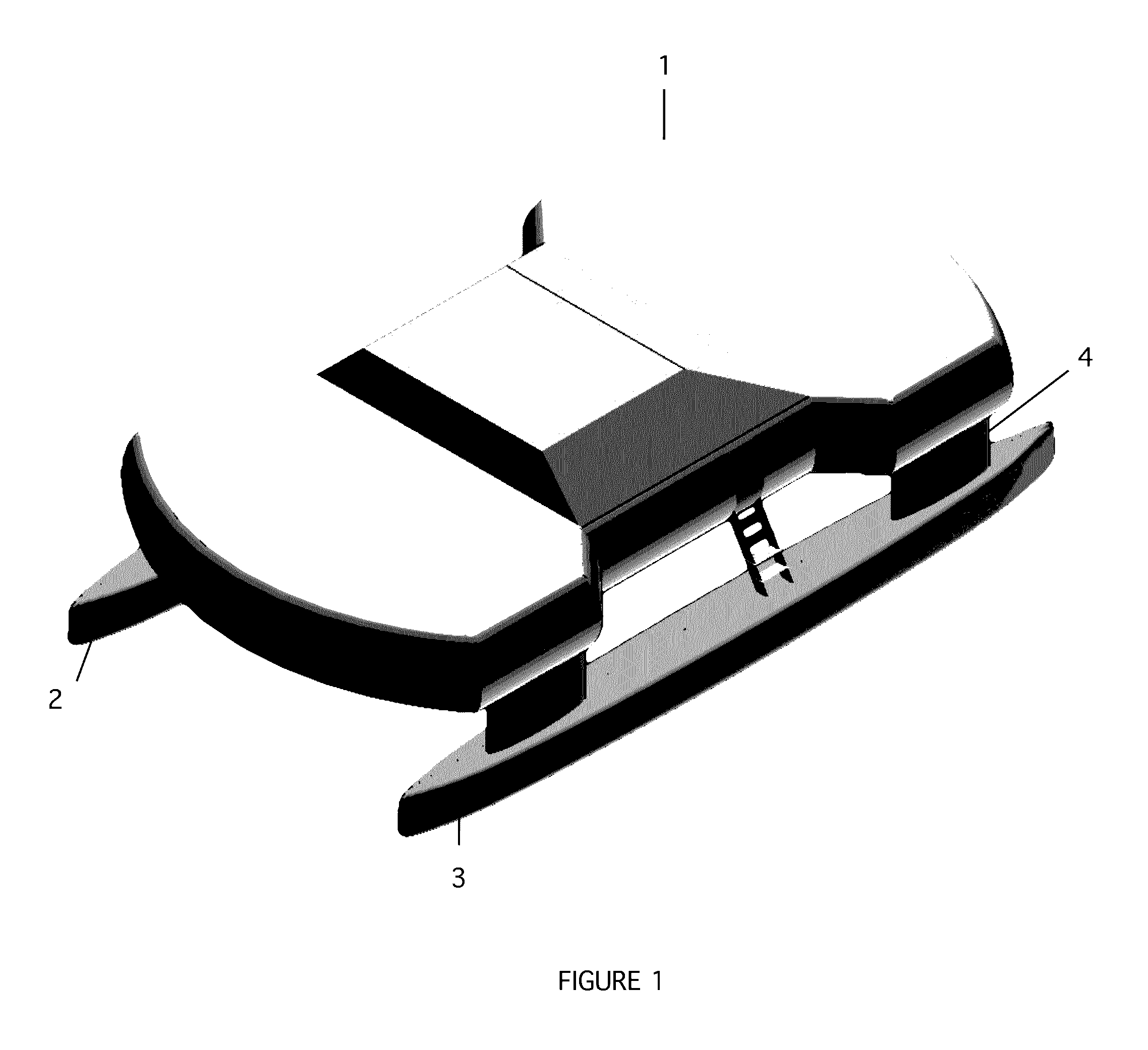
[0015] FIG. 1 is a perspective view of the multihull watercraft in a powerboat configuration (without sails).
[0016] FIG. 2 is a perspective view of the multihull watercraft showing an improved embodiment of the upper hull support structures.
[0017] FIG. 3 is a top view of the powerboat configuration that shows the upper hull and left and right float hulls.
[0018] FIG. 4 is a rear view that shows the dinghy storage compartment door lowered to a position adjacent to the right float hull, whereby the dinghy can easily be moved out of the compartment, across the top side of the float hull and pushed into the water for boarding. The compartment door is illustrated as being hinged on the inboard side, however an alternative embodiment could lower the entire door (and dinghy) to an altitude matching the float hull deck.
[0019] FIG. 5 is a perspective view depicting the deployment of a dinghy across the float hull and into the water where it may be boarded
[0020] FIG. 6 is a perspective view showing an alternate embodiment wherein the dinghy is lowered from the under-hull storage compartment directly into the water for boarding via the deck of the adjacent float hull.
[0021] FIG. 7 is a perspective view of the multihull watercraft in a sailboat configuration with the basic embodiment of the sailing rig.
[0022] FIG. 8 is a detailed view of the sailing rig basic embodiment.
[0023] FIG. 9 illustrates an improved embodiment of the sailing rig with the addition of forward and aft booms
[0024] FIG. 10 illustrates further improvements to the sailing rig with the addition of boom travelers and boom tensioning lines
[0025] FIG. 11 illustrates a modification to the embodiment of FIG. 9 wherein the mast is supported by a bearing means that allows the entire mast to rotate to the optimum position relative to the wind.
[0026] FIG. 12 illustrates a modification to the embodiment of FIG. 10 wherein the mast is supported by a bearing means that allows the entire mast to rotate to the optimum position relative to the wind.
DETAILED DESCRIPTION OF THE INVENTION
[0027] FIG. 1 illustrates an embodiment of the present invention in a powerboat configuration (without sails). A large upper hull 1 is suspended over a left float hull 2 and right float hull 3 by means of four support structures 4. The wide support structures shown in FIG. 1 may be improved by utilizing two or more narrow beams per support structure, which allows lateral air flow and thereby reduces lateral windage. The improved support structure 4 is shown in FIG. 2.
[0028] The top-view diagram in FIG. 3 illustrates the relative width of the upper hull 1 in comparison to the twin float hulls 2 and 3. The forward and aft portions of the upper hull enclose the passenger cabins, and extend laterally beyond the longitudinal centerline of the left and right float hulls to maximize the accommodation space. The middle portion of the upper hull encloses the common areas (salon, galley, storage, etc), and is constrained to the region inboard of the longitudinal centerline of the left and right float hulls. This unique configuration creates deck areas 5 and 6 on the top of both float hulls thereby making it safer and easier to board, dock, and access shore craft. The deck areas also serve as recreation space and swim platforms.
[0029] FIG. 4 shows the preferred embodiment of the shore craft storage and deployment means which includes a dinghy storage compartment door 7 which can be lowered to provide access to the dinghy 8. The compartment door is opened by a lowering mechanism 9 attached to the door. FIG. 5 is a perspective view showing how the dinghy can be moved out of the storage compartment, and across the adjacent deck and into the water.
[0030] FIG. 6 shows an alternate embodiment where the dinghy 8 is lowered directly into the water via a lowering mechanism 9, where it may be boarded via the inboard edge of the adjacent float hull deck 6. The lowering mechanism 9 in either embodiment is rope or synthetic line attached to a conventional manual winch, electric winch, or equivalent means such as a hydraulic piston.
[0031] FIG. 7 shows the multihull watercraft in a sailing configuration. The sailing rig includes a mast 10, a forward stay 11 and an aft stay 12. Both stays are attached to a pivoting member 13 at the top end of the mast, with a bearing 14 that allows the member to rotate freely.
[0032] A forward sail 15 is suspended between the forward stay and the mast. An aft sail 16 is suspended between the aft stay and the mast. The manner in which the sails are attached to the mast and stays is not relevant to the present invention, and may include any of the conventional elements such as bolt rope and tracks, hanks, or roller furling devices.
[0033] The bottom end of the forward stay connects to a sliding car 17 that runs along a curved forward track 18 that is rigidly fixed to the the boat forward of the mast. Similarly, the aft stay 12 connects to an aft sliding car 19 which runs along an aft curved track 20 located aft of the mast. The sliding cars and track are commonly used on sailing rigs and are widely available from marine equipment suppliers, however the specific design of the car is not important. Any type of sliding car and track that can withstand the tension applied by the stays may be used, thus the scope of the invention is defined by the claims and not limited by the specification. The track can be mounted on a horizontal deck surface as shown in FIG. 7, or alternately may be mounted on the exterior surface of the upper hull.
[0034] The curved tracks 18 and 20 are shaped with a constant radius of curvature equal to the distance between the track and the mast, and the sliding cars are installed at opposing positions relative to the mast (180 degrees apart). This ensures that the stays do not apply any lateral force on the top of the mast, only a compression force pushing the mast downward.
[0035] A car positioning means moves the cars to any desired location on their tracks while still maintaing their relative positions at 180 degrees. One embodiment is illustrated in FIG. 8. A continuous control line 21 runs in a loop through both tracks, then routed through a set of pulleys 22 (as many as needed), and around a manual or electric winch 23 that can move the control line in either direction. When the winch is turned the sliding cars will move simultaneously, causing the stays and attached sails to rotate about the mast to a new position appropriate for the current wind direction.
[0036] When the watercraft is sailing, the prevailing wind applies pressure on the forward sail and aft sail simultaneously, which in turn applies pressure to the slider cars and control line. Since the cars are controlled by a single control line in a loop, the pressure on the forward sail counteracts the pressure on the aft sail, which means the rig can be rotated even under load with only moderate force on the rotation control line.
[0037] The winch 23 shown in in FIG. 8 could alternately be replaced with an upright spoked wheel 24 of the type used to steer a boat, as shown in FIG. 9. The large wheel would provide a mechanical advantage as well as inertia when in motion that allows the skipper to quickly rotate the sailing rig to a new position.
[0038] An alternate embodiment of the car positioning means could place the control line alongside the track guided by pulley wheels, instead of running inside the track as illustrated. Many other equivalent means may be used to perform the same car positioning function, including linear actuators or hydraulic devices that move the control lines or cars directly, or electric motors that attach to the car and engage the track using wheels or gear teeth. Thus the scope of the invention is defined by the attached claims and their equivalent means, rather than the examples cited.
[0039] The sailing rig described above may be enhanced in order to accommodate larger sails for more propulsive power. FIG. 9 illustrates the sailing rig with the addition of a forward boom 25, an aft boom 26, and a mast collar 27 with internal bearings that allow it to rotate freely around the mast. The booms connect at one end to their respective stays, and to the rotating mast collar at the other end. The car positioning means includes the control line loop 21 and a control wheel 24, however any of the alternate car positioning means mentioned previously may be used.
[0040] With the booms installed, the forward and aft stays are pushed farther away from the mast, which allows for larger sail area without increasing mast height or boat length. There is also the benefit that the stays are less likely to come into contact with passengers or equipment on the deck.
[0041] The sailing rig described above can be further enhanced as shown in FIG. 10. Traveler mechanisms 27 and 28 are added to the underside of the forward and aft booms (each traveler is comprised of a sliding car and track, but for clarity the combination of elements in this case will be designated as a traveler). Tensioning lines 29 and 30 connect the forward and aft travelers to the sliding cars 17 and 19 on the deck tracks 18 and 20. The boom traveler effectively allows the connecting point to move along the boom, so the tensioning lines will always remain in a nominally vertical orientation as the sliding cars below them move along the track.
[0042] The added elements in this configuration of the sailing rig provide two important benefits. First, the deck tracks no longer need to have constant radius of curvature, so there's more flexibility in where they are installed. Second, the tracks can be extended further amidships (toward the mast) to allow greater rotation of the sailing rig in either direction, as illustrated in FIG. 10. This allows the boat to sail more efficiently in a wider range of wind conditions.
[0043] In the embodiment illustrated in FIG. 9 the pivot means 14 allows the forward and aft stays to rotate around the mast. The rotating collar 27 allows the booms to rotate around the mast in a similar manner. In an alternate embodiment, the entire mast is supported by a mast bearing means 31 shown in FIG. 11. The mast bearing means is anchored within the deck of the boat and contains ball bearings, roller bearings, or functionally equivalent elements and is a well-known mechanism in the marine industry. This allows the entire mast to rotate and eliminates the need for the pivot means (for the stays) at the top of the mast and the rotating collar (for the booms) near the bottom of the mast. This enhancement provides improved aerodynamic performance when used with a mast with an airfoil crosssection. Rotating the entire sailing rig to the optimum position also puts the mast in the optimum orientation to reduce drag.
[0044] In the embodiment illustrated in FIG. 10 the pivot means 14 and rotating collar 27 allows the sailing rig to rotate as discussed above. In an alternate embodiment, the entire mast is supported by a mast bearing means 31 shown in FIG. 12. This allows the entire mast to rotate, and eliminates the need for the pivot means at the top of the mast and the rotating collar near the bottom of the mast. This enhancement provides improved aerodynamic performance as discussed with the embodiment of FIG. 11.
CONCLUSION
[0045] The patent discloses a multihull watercraft with a unique hull configuration providing numerous benefits, an improved means for dinghy storage and deployment, and a new simplified sailing rig that is easier to operate and maintain than the conventional Bermuda rig. The scope of the present is not limited to the examples provided in the specification, but is defined by the claims.
* * * * *
D00000
D00001
D00002
D00003
D00004
D00005
D00006
D00007
D00008
D00009
D00010
D00011
D00012

XML
uspto.report is an independent third-party trademark research tool that is not affiliated, endorsed, or sponsored by the United States Patent and Trademark Office (USPTO) or any other governmental organization. The information provided by uspto.report is based on publicly available data at the time of writing and is intended for informational purposes only.
While we strive to provide accurate and up-to-date information, we do not guarantee the accuracy, completeness, reliability, or suitability of the information displayed on this site. The use of this site is at your own risk. Any reliance you place on such information is therefore strictly at your own risk.
All official trademark data, including owner information, should be verified by visiting the official USPTO website at www.uspto.gov. This site is not intended to replace professional legal advice and should not be used as a substitute for consulting with a legal professional who is knowledgeable about trademark law.