Methods And Devices For Minimally-invasive Delivery Of Radiation To The Eye
Lutz; Wendell ; et al.
U.S. patent application number 14/486401 was filed with the patent office on 2016-12-29 for methods and devices for minimally-invasive delivery of radiation to the eye. The applicant listed for this patent is Salutaris Medical Devices, Inc.. Invention is credited to Thomas C. Cetas, Russell J. Hamilton, Samuel S. Hyman, Wendell Lutz, Laurence J. Marsteller, Timothy Shriver.
| Application Number | 20160375267 14/486401 |
| Document ID | / |
| Family ID | 57601375 |
| Filed Date | 2016-12-29 |


View All Diagrams
| United States Patent Application | 20160375267 |
| Kind Code | A1 |
| Lutz; Wendell ; et al. | December 29, 2016 |
METHODS AND DEVICES FOR MINIMALLY-INVASIVE DELIVERY OF RADIATION TO THE EYE
Abstract
Methods and devices for minimally-invasive delivery of radiation to the eye (such as the posterior portion of the eye) including cannula systems with multiple treatment positions and/or multiple channels in the distal tip of the cannula systems. The channels can accommodate emanating sources and exposing a target at various treatment positions. The emanating sources may be annulus-shaped.
| Inventors: | Lutz; Wendell; (Tucson, AZ) ; Hamilton; Russell J.; (Tucson, AZ) ; Cetas; Thomas C.; (Tucson, AZ) ; Marsteller; Laurence J.; (Tucson, AZ) ; Shriver; Timothy; (Vail, AZ) ; Hyman; Samuel S.; (Tucson, AZ) | ||||||||||
| Applicant: |
|
||||||||||
|---|---|---|---|---|---|---|---|---|---|---|---|
| Family ID: | 57601375 | ||||||||||
| Appl. No.: | 14/486401 | ||||||||||
| Filed: | September 15, 2014 |
Related U.S. Patent Documents
| Application Number | Filing Date | Patent Number | ||
|---|---|---|---|---|
| 14011516 | Aug 27, 2013 | 9056201 | ||
| 14486401 | ||||
| 13953528 | Jul 29, 2013 | |||
| 14011516 | ||||
| 13872941 | Apr 29, 2013 | |||
| 13953528 | ||||
| 13872941 | Apr 29, 2013 | |||
| 14011516 | ||||
| 12350079 | Jan 7, 2009 | 8430804 | ||
| 13872941 | ||||
| 13742823 | Jan 16, 2013 | 8597169 | ||
| 14011516 | ||||
| 12497644 | Jul 3, 2009 | |||
| 13742823 | ||||
| 12350079 | Jan 7, 2009 | 8430804 | ||
| 12497644 | ||||
| 13111780 | May 19, 2011 | 8608632 | ||
| 14011516 | ||||
| 12497644 | Jul 3, 2009 | |||
| 13111780 | ||||
| 12350079 | Jan 7, 2009 | 8430804 | ||
| 12497644 | ||||
| 12917044 | Nov 1, 2010 | |||
| 14011516 | ||||
| 13111765 | May 19, 2011 | 8602959 | ||
| 14011516 | ||||
| 13953528 | Jul 29, 2013 | |||
| 14011516 | ||||
| 61877765 | Sep 13, 2013 | |||
| 61347226 | May 21, 2010 | |||
| 61010322 | Jan 7, 2008 | |||
| 61033238 | Mar 3, 2008 | |||
| 61035371 | Mar 10, 2008 | |||
| 61047693 | Apr 24, 2008 | |||
| 61376115 | Aug 23, 2010 | |||
| 61257232 | Nov 2, 2009 | |||
| 61347233 | May 21, 2010 | |||
| 61676783 | Jul 27, 2012 | |||
| Current U.S. Class: | 600/7 ; 600/8 |
| Current CPC Class: | A61N 2005/1024 20130101; A61F 9/00 20130101; A61M 2210/0612 20130101; A61B 1/06 20130101; A61N 5/1017 20130101; A61N 2005/1008 20130101; A61N 5/1007 20130101 |
| International Class: | A61N 5/10 20060101 A61N005/10; A61B 1/06 20060101 A61B001/06 |
Claims
1-19. (canceled)
20. An emanating source system, the emanating source system comprising an emanating source (401) whereby the radiation emission shape (406) is in the shape of an annulus or partial annulus.
21. The emanating source system of claim 20, wherein the emanating source (401) comprises an attenuation zone (410),
22. The emanating source system of claim 21, where the attenuation zone (410) is an indentation in a surface of the emanating source (401).
23. The emanating source system of claim 21, where the attenuation zone comprises a shield.
24. The emanating source system of claim 21, where the attenuation zone reduces radiation emitted from attenuation zone region.
25. The emanating source system of claim 21, where the attenuation zone eliminates radiation emitted from the attenuation zone region.
26. The emanating source system of claim 20, where the emanating source (401) has a substantially flat dose rate at the center of a target as well as across a target,
27. The emanating source system of claim 21, wherein the dose emitted from the attenuation zone is about 10% less than the dose emitted from the outer edge (412) of the attenuation zone.
28. The emanating source system of claim 21, wherein the dose emitted from the attenuation zone is about 20% less than the dose emitted from the outer edge (412) of the attenuation zone.
29. The emanating source system of claim 21, wherein the dose emitted from the attenuation zone is about 50% less than the dose emitted from the outer edge (412) of the attenuation zone.
30. The emanating source system of claim 21, wherein the dose emitted from the attenuation zone is about 80% less than the dose emitted from the outer edge (412) of the attenuation zone.
31. The emanating source system of claim 21, wherein the dose emitted from the attenuation zone is about 90% less than the dose emitted from the outer edge (412) of the attenuation zone.
32. The emanating source system of claim 20, wherein the emanating source is complexed with a carrier.
33. The emanating source system of claim 20, wherein the emanating source is complexed with a radiation shaper.
34. An emanating source system comprising an emanating source (401) whereby the radiation emission shape (406) is in the shape of an annulus or partial annulus; and a cannula system (100) comprising a distal portion (110) with a tip (112), wherein the emanating source (401) is disposed at a treatment position (118) in the tip (112).
35. The emanating source system of claim 34, wherein the emanating source (401) comprises an attenuation zone (410).
36. The emanating source system of claim 35, where the attenuation zone (410) is an indentation in a surface of the emanating source (401).
37. The emanating source system of claim 35, where the attenuation zone comprises a shield.
38. The emanating source system of claim 35, where the attenuation zone reduces radiation emitted from attenuation zone region.
Description
CROSS REFERENCE
[0001] This application is a non-provisional of U.S. Provisional Patent Application No. 61/877,765, filed Sep. 13, 2013, the specification(s) of which is/are incorporated herein in their entirety by reference.
[0002] This application also claims priority to U.S. patent application Ser. No. 13/872/941, filed Apr. 29, 2013, which is a division of U.S. patent application Ser. No. 12/350,079, filed Jan. 7, 2009, which is a non-provisional of U.S. Provisional Application No. 61/010,322, filed Jan. 7, 2008, U.S. Provisional Application No. 61/033,238, filed Mar. 3, 2008, U.S. Provisional Application No. 61/035,371, filed Mar. 10, 2008, and U.S. Provisional Application No. 61/047,693, filed Apr. 24, 2008, the specification(s) of which is/are incorporated herein in their entirety by reference.
[0003] This application also claims priority to U.S. patent application Ser. No. 13/953,528, filed Jul. 29, 2013, which is a non-provisional of U.S. Provisional Application No. 61/676,783, filed Jul. 27, 2012, the specification(s) of which is/are incorporated herein in their entirety by reference.
[0004] This application also claims priority to U.S. patent application Ser. No. 14/011,516, filed Aug. 27, 2013, which claims priority to U.S. patent application Ser. No. 13/742,823, filed Jan. 16, 2013, which is a continuation of U.S. patent application Ser. No. 12/497,644, filed Jul. 3, 2009, which is a continuation-in-part of U.S. patent application Ser. No. 12/350,079, filed Jan. 7, 2009, which is a non-provisional of U.S. Provisional Application No. 61/010,322, filed Jan. 7, 2008, U.S. Provisional Application No. 61/033,238, filed Mar. 3, 2008, U.S. Provisional Application No. 61/035,371, filed Mar. 10, 2008, and U.S. Provisional Application No. 61/047,693, filed Apr. 24, 2008, the specification(s) of which is/are incorporated herein in their entirety by reference. Application Ser. No. 14/011,516 also claims priority to U.S. patent application Ser. No. 13/111,780, filed May 19, 2011, which is a non-provisional of U.S. Provisional Application No. 61/347,226, filed May 21, 2010; and a continuation-in-part of U.S. patent application Ser. No. 12/497,644, filed Jul. 3, 2009, which is a continuation-in-part of U.S. patent application Ser. No. 12/350,079, filed Jan. 7, 2009, which is a non-provisional of U.S. Provisional Application No. 61/010,322, filed Jan. 7, 2008, U.S. Provisional Application No. 61/033,238, filed Mar. 3, 2008, U.S. Provisional Application No. 61/035,371, filed Mar. 10, 2008, and U.S. Provisional Application No. 61/047,693, filed Apr. 24, 2008, the specification(s) of which is/are incorporated herein in their entirety by reference. Application Ser. No. 14/011,516 also claims priority to U.S. patent application Ser. No. 12/917,044, filed Nov. 1, 2010, which is a non-provisional of U.S. Provisional Application No. 61/257,232, filed Nov. 2, 2009 and U.S. Provisional Application No. 61/376,115, filed Aug. 23, 2010, the specification(s) of which is/are incorporated herein in their entirety by reference. Application Ser. No. 14/011,516 also claims priority to U.S. patent application Ser. No. 13/111,765, filed May 19, 2011, which is a non-provisional of U.S. Provisional Application No. 61/347,233, filed May 21, 2010, the specification(s) of which is/are incorporated herein in their entirety by reference. Application Ser. No. 14/011,516 also claims priority to U.S. patent application Ser. No. 13/953,528, filed Jul. 29, 2013, which is a non-provisional of U.S. Provisional Application No. 61/676,783, filed Jul. 27, 2012, the specification(s) of which is/are incorporated herein in their entirety by reference.
FIELD OF THE INVENTION
[0005] The present invention relates to methods and devices for introducing radiation to the eye, e.g., the posterior portion of the eye, for treating and/or managing eye conditions including but not limited to macular degeneration.
BACKGROUND OF THE INVENTION
[0006] The present invention features methods and devices for minimally-invasive delivery of radiation to the eye, e.g., the posterior portion of the eye. For example, the present invention features cannula systems and afterloading systems (e.g., remote afterloading systems) for introducing emanating sources (e.g., active material, radionuclide brachytherapy sources) to the cannula systems for irradiating targets (e.g., targets of the eye). The emanating source may be, for example, introduced into the cannula system via an afterloading system following cannula system insertion and positioning.
[0007] Presently, workers in the field of radiation therapy believe that a barrel-shaped or disk-shaped radiation projection at the surface of the radiation source is the proper radiation profile for treating neovascular lesion of wet AMD. We have surprisingly discovered that radiation flux with an attenuation zone, e.g., a centrally disposed attenuation zone, provides for more effective treatment of neovascular lesion of wet AMD from the posterior episcleral surface.
[0008] Any feature or combination of features described herein are included within the scope of the present invention provided that the features included in any such combination are not mutually inconsistent as will be apparent from the context, this specification, and the knowledge of one of ordinary skill in the art. Additional advantages and aspects of the present invention are apparent in the following detailed description and claims.
BRIEF DESCRIPTION OF THE DRAWINGS
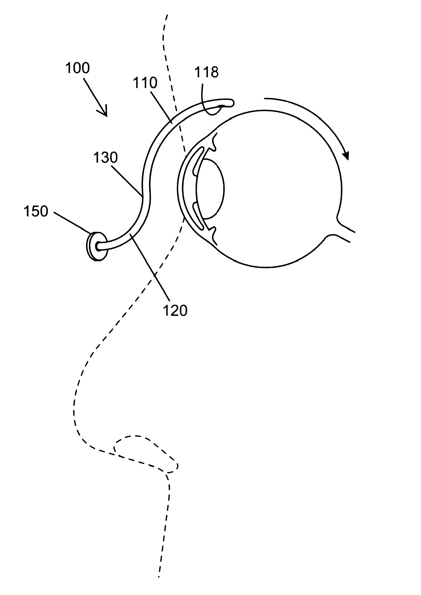
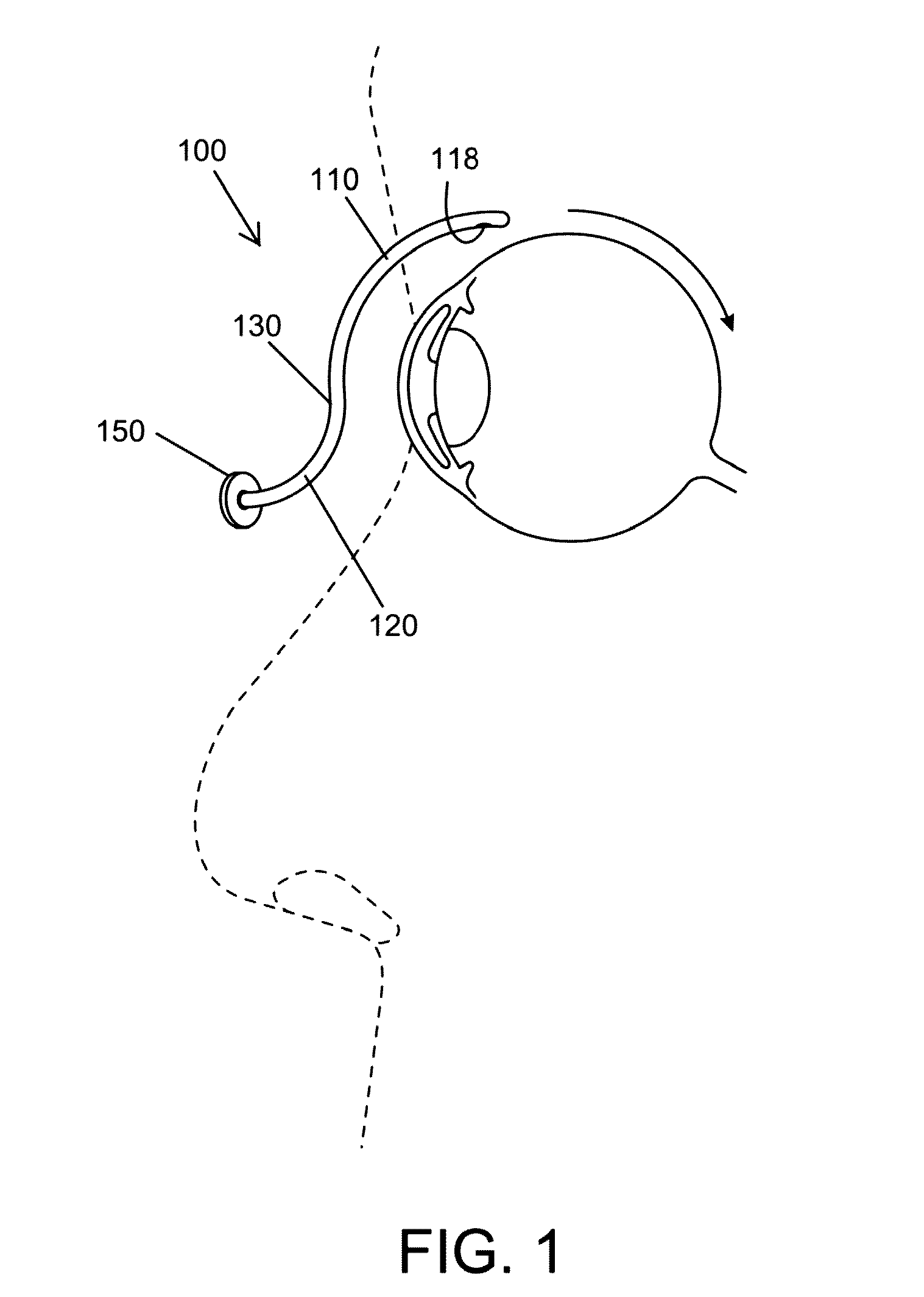
[0009] FIG. 1 shows an in-use view of a cannula system of the present invention.
[0010] FIG. 2 shows a schematic view of an afterloading system of the present invention. Afterloading systems are well known to one of ordinary skill in the art. The present invention is not limited to the afterloading systems described herein.
[0011] FIG. 3A shows the advancing means and emanating source within the guide tube.
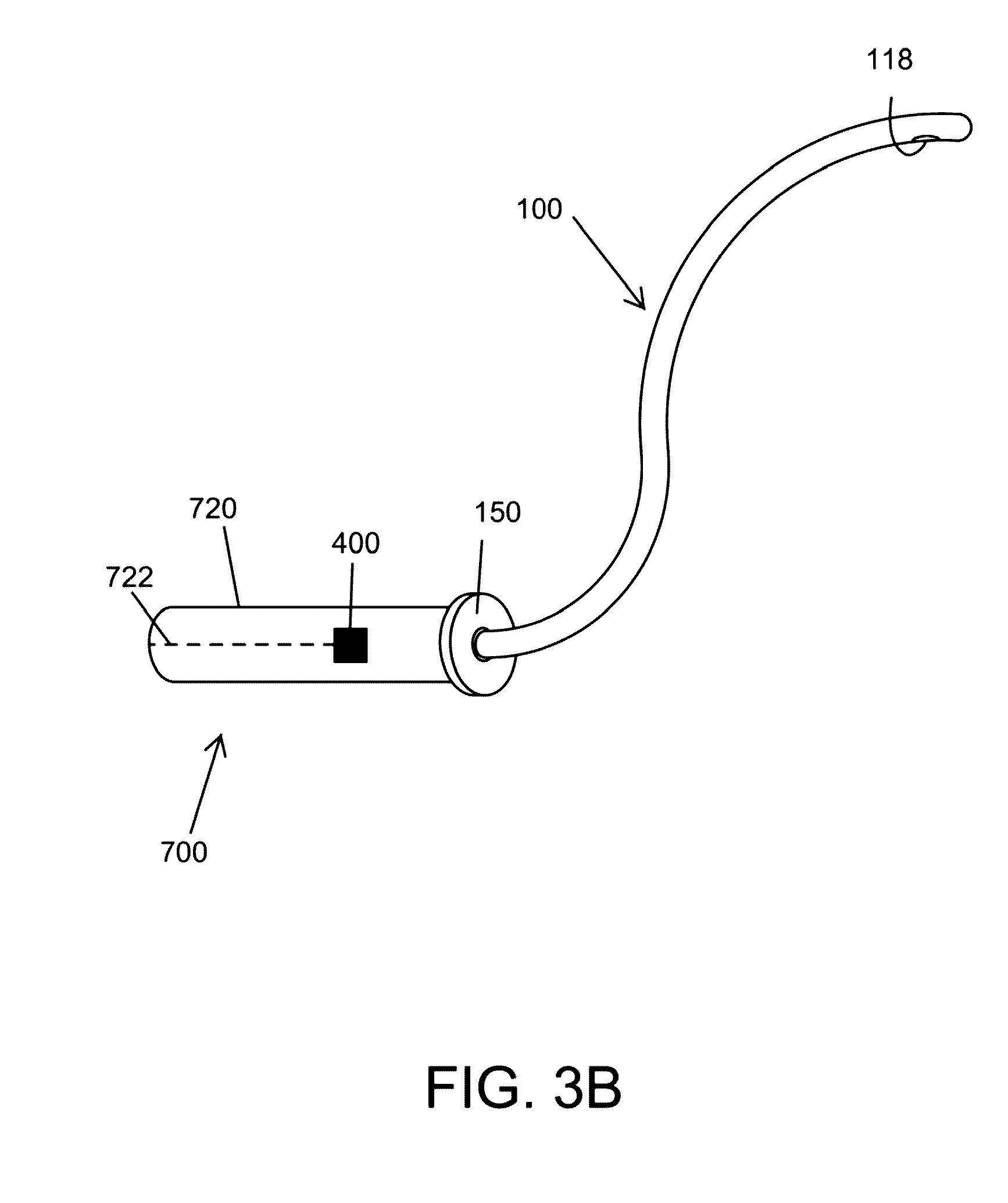
[0012] FIG. 3B shows the guide tube connecting to the cannula system.
[0013] FIG. 4A shows a detailed view of the distal portion of a cannula system comprising a single channel through which an emanating source can travel. The cannula system comprises a plurality of treatment positions within the channel (e.g., treatment position 1, treatment position 2, treatment position n, treatment position n+1, etc.).
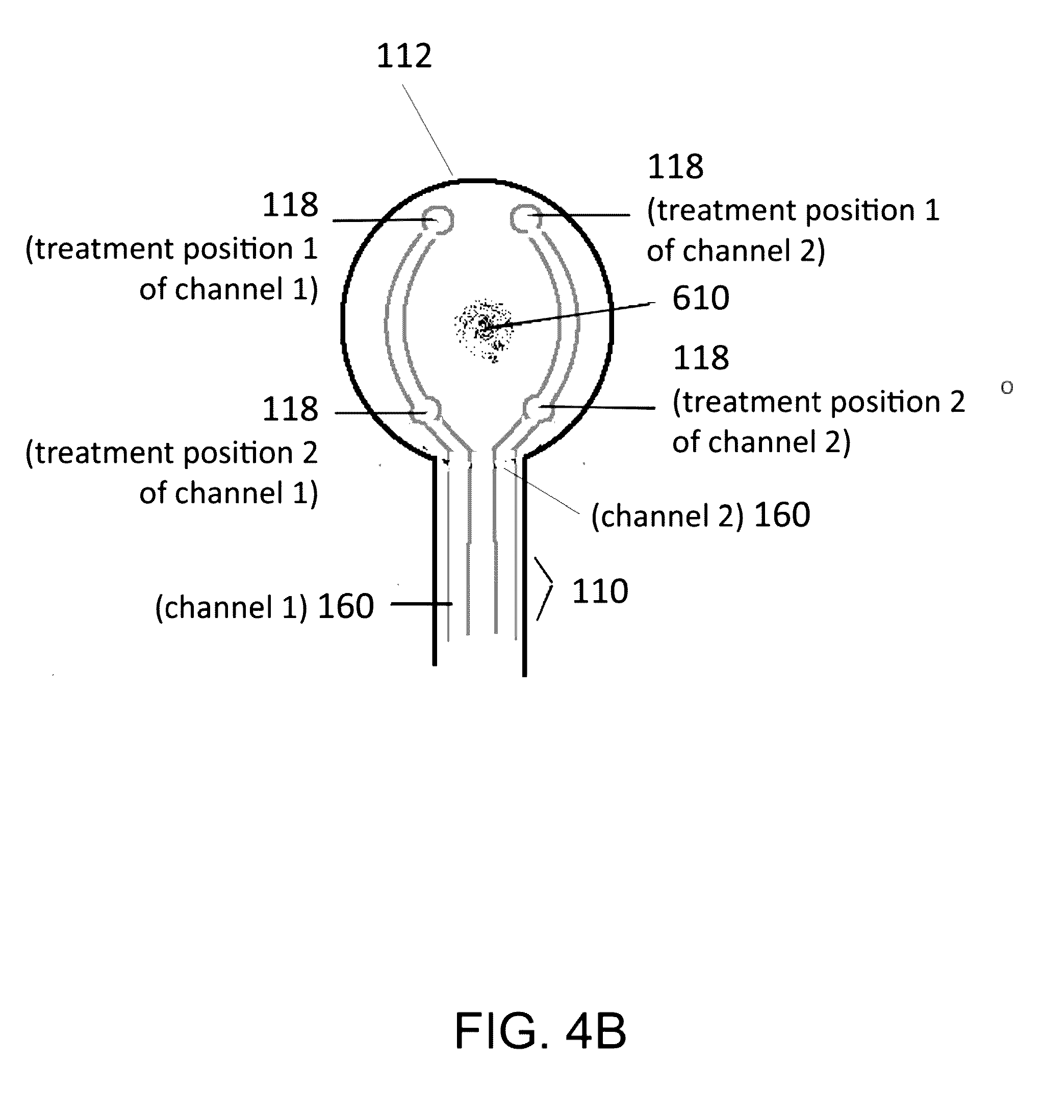
[0014] FIG. 4B shows a detailed view of the distal portion of a cannula system comprising more than one channel (e.g., 2 channels) through which an emanating source can travel, wherein the channels each comprise more than one treatment position (e.g., treatment position 1, treatment position 2) for the emanating source.
[0015] FIG. 5A is a perspective view of an embodiment of the present invention. The tip of the distal portion of the cannula system has a disk-like shape (e.g., an annulus).
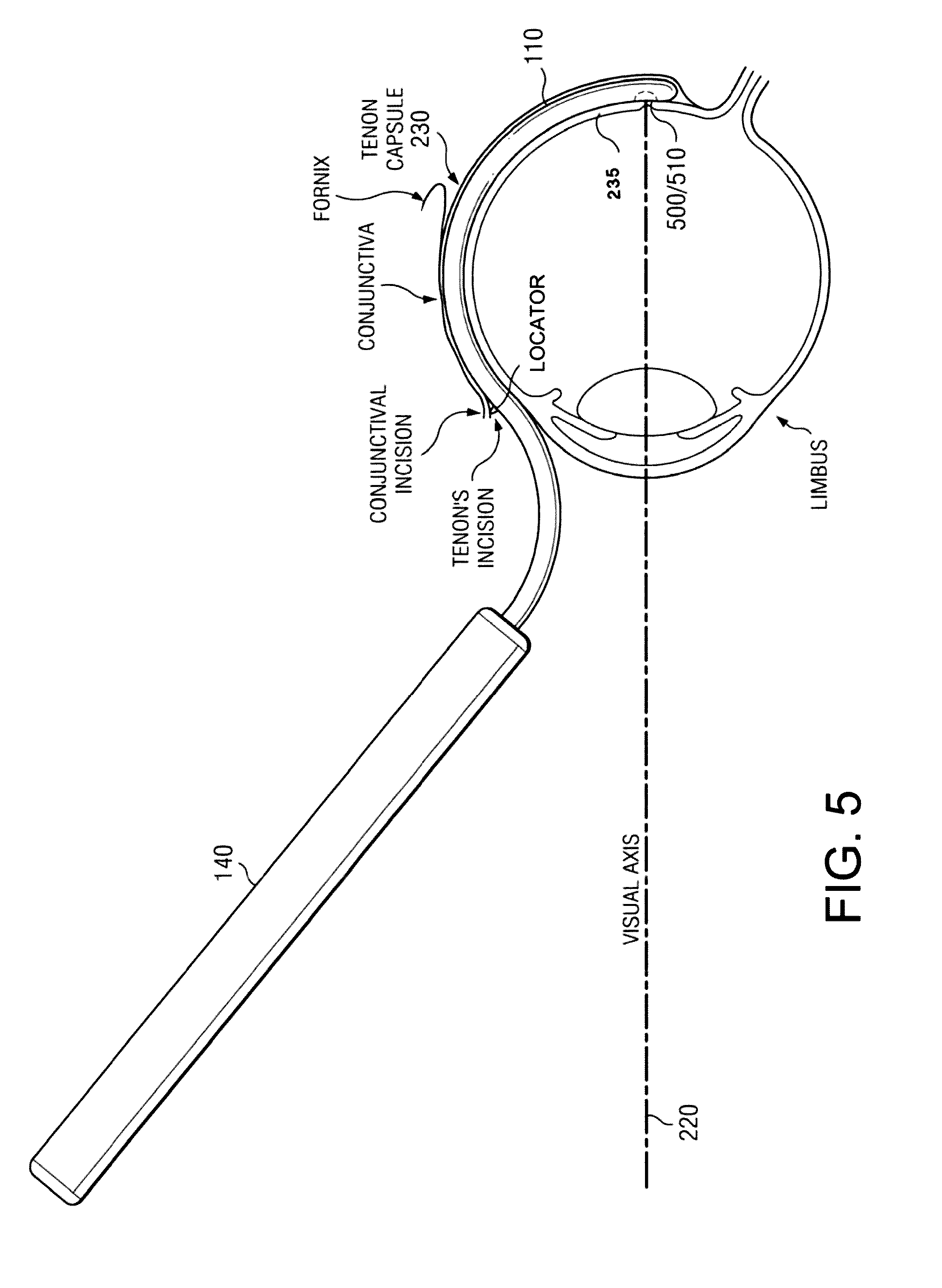
[0016] FIG. 5B is an in-use view of the system of FIG. 5A (for clarity, cannula is not shown under Tenon's capsule). The tip of the cannula system is positioned at the back of the eye.
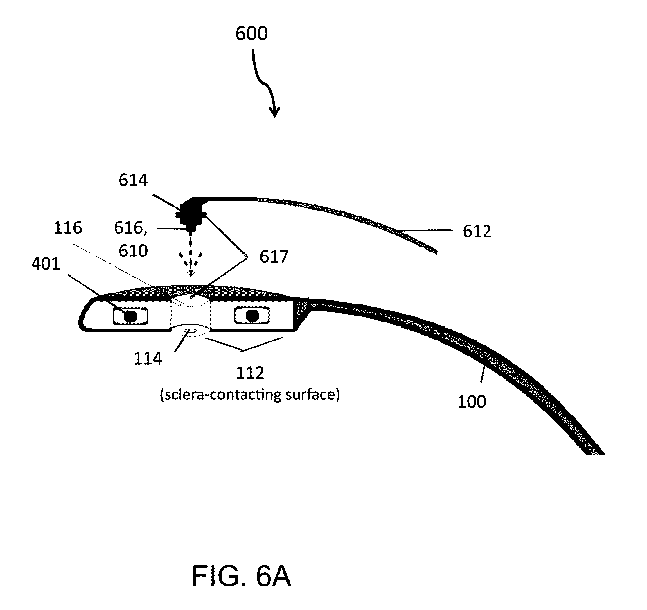
[0017] FIG. 6A shows a side view of a light source assembly.
[0018] FIG. 6B shows a perspective view of a light source assembly.
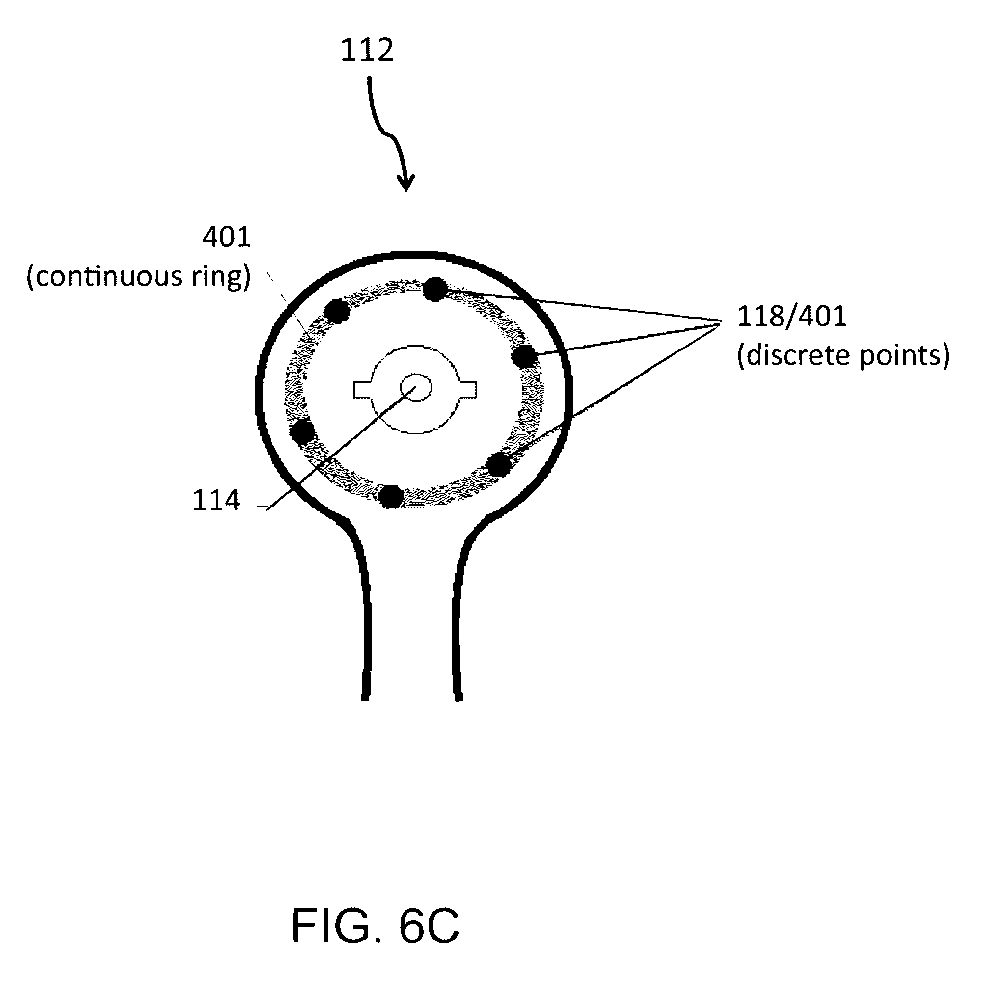
[0019] FIG. 6C shows a bottom view of the light source assembly of FIG. 6B (as viewed from the bottom (or sclera-contacting surface) of the tip of the distal portion of the cannula system). The emanating source may be discrete units or a continuous ring (or partial ring, not shown). The emanating sources are not limited to these configurations.
[0020] FIG. 7A shows the annulus-shaped emanating source at the tip of a cannula system.
[0021] FIG. 7B shows an emanating source with an annulus-like radiation profile disposed in the tip of the cannula system (100).
[0022] FIG. 8 shows an annulus-shaped emanating source and an emanating source that has an annulus-shaped radiation emission shape because of the radiation shaper positioned between the target and the emanating source.
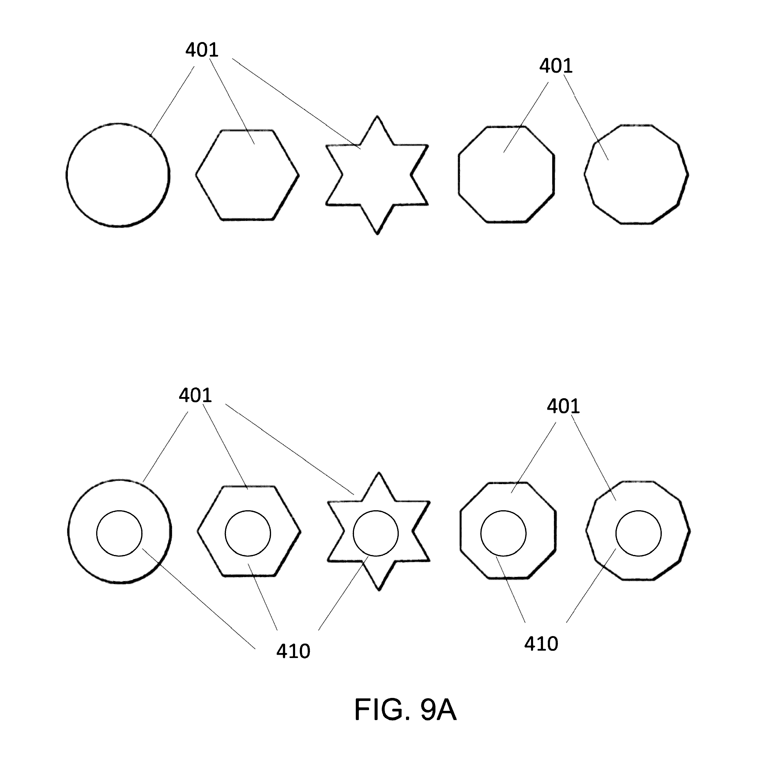
[0023] FIG. 9A shows examples of emanating sources (or radiation emission shapes).
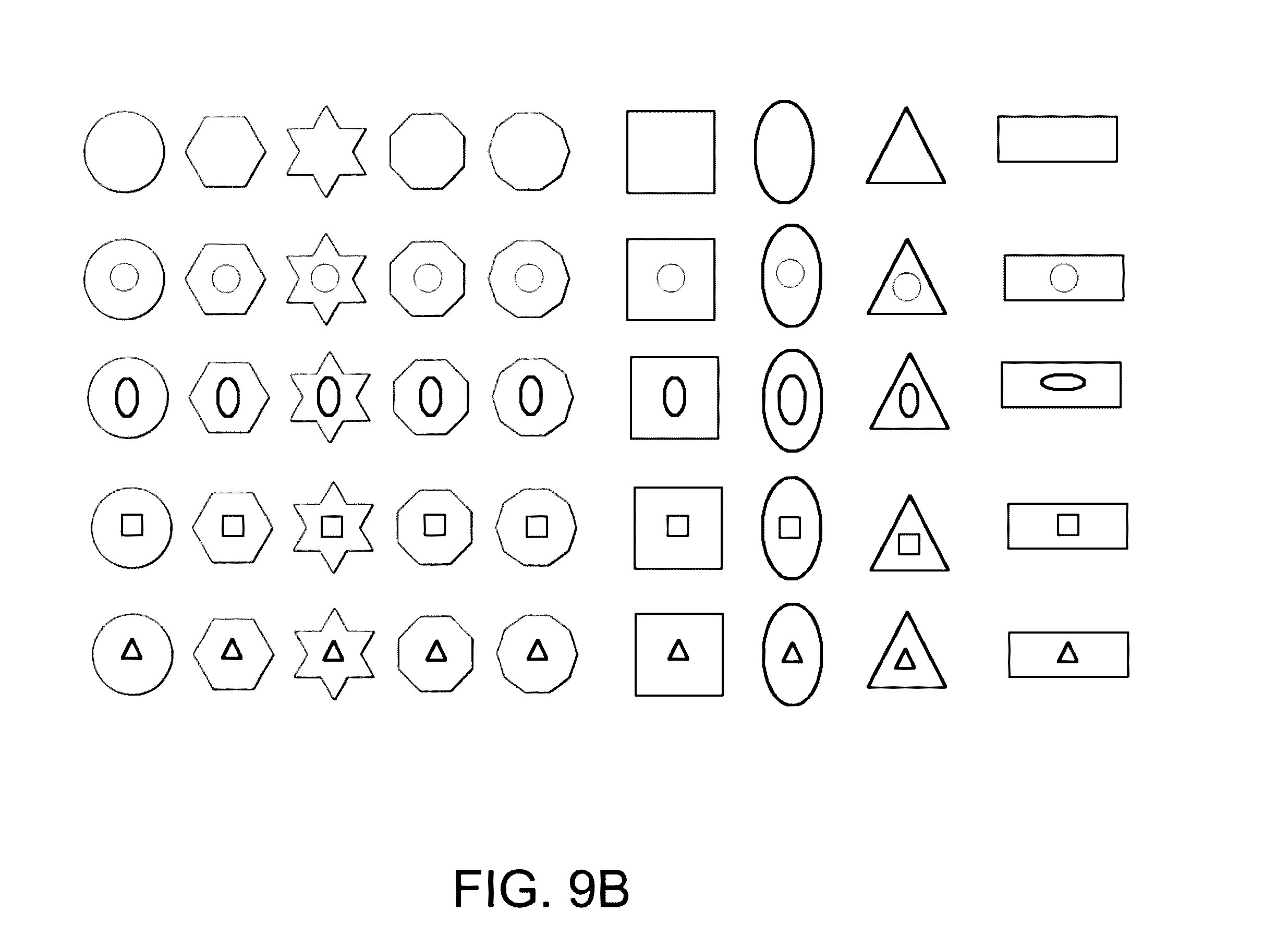
[0024] FIG. 9B shows additional examples of emanating sources (or radiation emission shapes) with attenuation zones.
[0025] FIG. 10 shows examples of emanating source shapes (or radiation emission shapes).
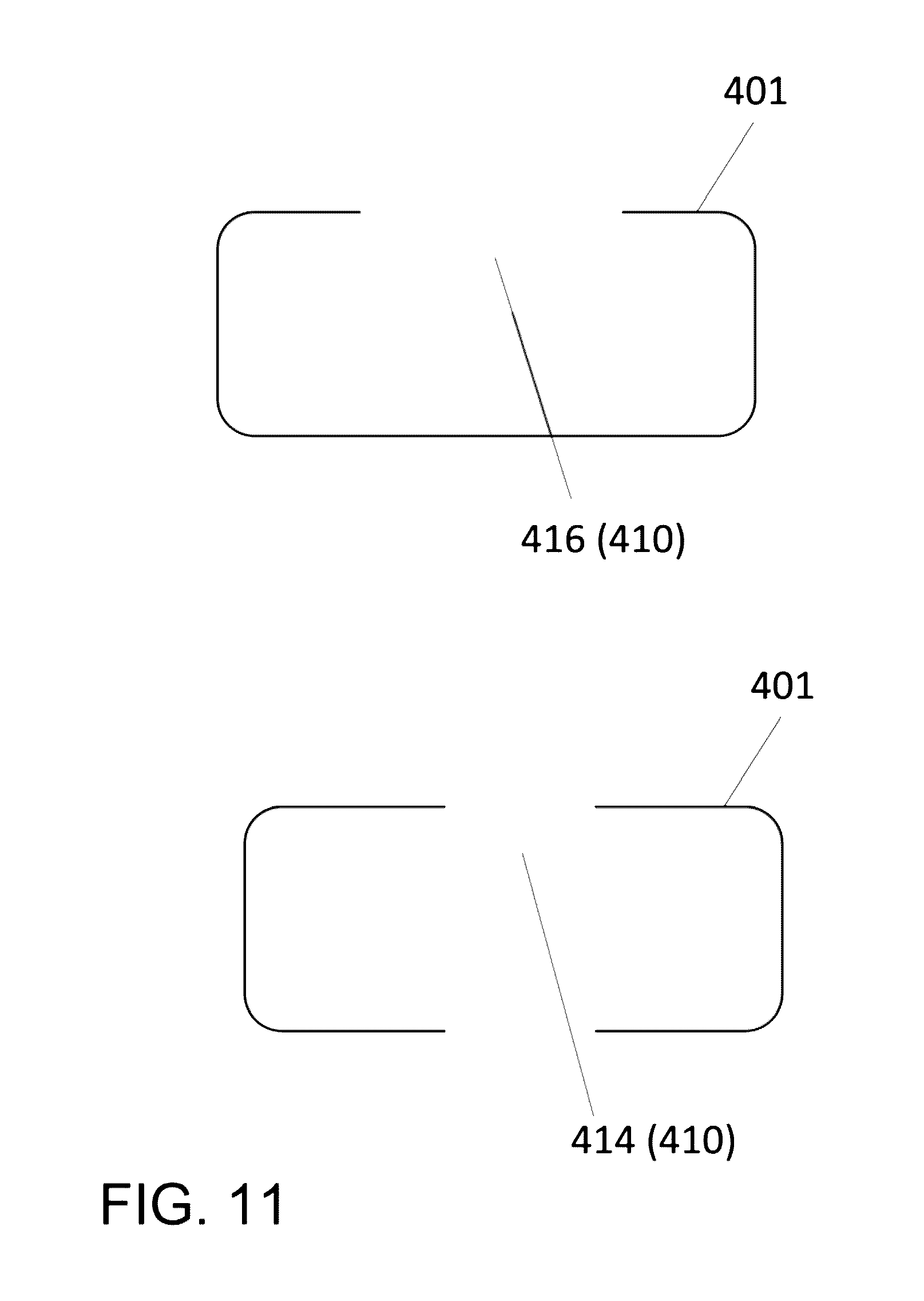
[0026] FIG. 11 shows side cross sectional views of two examples of emanating source configurations, one with an indentation and one with a hole.
[0027] FIG. 12 shows radiation flux for two annulus emanating sources: (a) an annulus-shaped emanating source and a disc-shaped emanating source paired with a radiation shaper. The resulting radiation emission shape is that of an annulus configuration.
DESCRIPTION OF PREFERRED EMBODIMENTS
[0028] Following is a list of elements corresponding to a particular element referred to herein: [0029] 100 cannula system [0030] 110 distal portion of cannula system [0031] 112 tip/distal end of distal portion of cannula system [0032] 113 center [0033] 114 light aperture in tip of distal portion of cannula system [0034] 116 light source plug compartment [0035] 118 treatment position [0036] 120 proximal portion of cannula system [0037] 130 inflection point of cannula system [0038] 150 connector (optional) [0039] 160 channel [0040] 401 emanating source [0041] 401a annulus-shaped emanating source [0042] 401b disc-shaped emanating source [0043] 402 jacket [0044] 404 radiation shaper [0045] 406 radiation emission shape [0046] 407 annulus-shaped radiation emission shape [0047] 410 attenuation zone [0048] 412 outer edge of attenuation zone [0049] 414 hole [0050] 416 indentation [0051] 450 radiation flux [0052] 600 light source assembly [0053] 610 light source emitter component [0054] 612 light pipe (e.g., fiber optic cable or other light guide) [0055] 613 prism [0056] 614 light source plug [0057] 616 tip of light source plug [0058] 617 locking mechanism [0059] 618 groove [0060] 700 afterloading system [0061] 710 vault [0062] 720 guide tube [0063] 722 advancing means (e.g., guide wire) [0064] 730 source-drive mechanism [0065] 732 motor [0066] 740 computer (e.g., microprocessor) [0067] 744 control console
[0068] Referring now to FIG. 1-12, the present invention features methods and devices for minimally-invasive delivery of radiation to the eye, e.g., the posterior portion of the eye. For example, the present invention features afterloading systems (700) (e.g., remote afterloading systems) for introducing en emanating source (401) to a cannula system (100). The cannula system (100) may be adapted for insertion into a potential space between the sclera and the Tenon's capsule of the eye of a patient.
[0069] The present methods and devices may be effective for treating and/or managing a condition (e.g., an eye condition). For example, the present methods and devices may be used to treat and/or manage wet (neovascular) age-related macular degeneration. The present methods are not limited to treating and/or managing wet (neovascular) age-related macular degeneration. For example, the present methods may also be used to apply superficial radiation to benign or malignant ocular growths (e.g., choroidal hemangioma, choroidal melanoma, retinoblastoma) and or to treat and/or manage conditions including macular degeneration, abnormal cell proliferation, choroidal neovascularization, retinopathy (e.g., diabetic retinopathy, vitreoretinopathy), macular edema, and tumors.
[0070] In some embodiments, the present invention features an emanating source system, the emanating source system comprising an emanating source (401) whereby the radiation emission shape (406) is in the shape of an annulus or partial annulus. In some embodiments, the emanating source (401) is in the shape of an annulus or a partial annulus. In some embodiments, the emanating source (401) comprises a plurality of discrete seeds that have a cumulative radiation emission shape (406) of an annulus or partial annulus. In some embodiments, the emanating source (401) comprises any arrangement of sources that yield a radiation emission shape (406) in the shape of an annulus or partial annulus. In some embodiments, the emanating source (401) comprises a radiation shaper (404); the radiation shaper (404) shapes the radiation emitted from the emanating source (401) into a radiation emission shape (406) in the shape of an annulus or partial annulus. In some embodiments, the emanating source (401) unit is housed in a jacket (402). In some embodiments, the emanating source (401) unit is attached to a cannula, a cannula system (100), a rod, or a stick.
[0071] In some embodiments, the present invention features a method of irradiating a target of an eye in a patient, said method comprising exposing a target of an eye with an emanating source (401) that has an radiation emission shape (406) of an annulus. In some embodiments, the target comprises a neovascular lesion of wet AMD. In some embodiments, the emanating source (401) is adjacent to the retrobulbar episcleral surface.
[0072] In some embodiments, the present invention features a method of irradiating a target of an eye in a patient, said method comprising inserting a cannula system into a potential space between a sclera and a Tenon's capsule of the eye of the patient; placing a distal portion (110) of the cannula system (100) on or near the sclera and positioning a treatment position (118) of a tip (112) of the distal portion (110) of the cannula system (100) near the target; advancing an emanating source (401) through the cannula system (100) to the treatment position (118) in the distal portion (110) of the cannula system (100), wherein the radiation emission shape (406) of the emanating source (401) creates a radiation emission shape (406) of an annulus; exposing the target to the emanating source (401); retracting the emanating source (401); and removing the cannula system (100). In some embodiments, the emanating source (401) comprises a single unit or a plurality of discrete units that are positioned either simultaneously or by sequential positioning. In some embodiments, the cannula system comprises a cannula system (100).
[0073] In some embodiments, the present invention features a method of irradiating a target of an eye in a patient, said method comprising advancing an emanating source (401) through a cannula system (100) to a treatment position (118) in a distal portion (110) of a cannula system (100); inserting the cannula system (100) into a potential space between a sclera and a Tenon's capsule of the eye of the patient; placing a distal portion (110) of the cannula system (100) on or near the sclera and positioning the treatment position (118) of the cannula system (100) near the target; exposing the target to the emanating source (401); and removing the cannula system (100). In some embodiments, the emanating source (401) comprises a single unit or a plurality of discrete units that are positioned either simultaneously or by sequential positioning. In some embodiments, the cannula system comprises a cannula system (100).
[0074] In some embodiments, the present invention features a brachytherapy system comprising a cannula system (100) for insertion into a potential space between a sclera and a Tenon's capsule of an eye of a patient. In some embodiments, the cannula system (100) comprises a distal portion (110) with a tip (112), a channel (160) extends through the cannula system (100) to the tip (112), the channel (160) comprises at least one treatment position (118) in the tip (112) for an emanating source (401).
[0075] In some embodiments, the cannula system (100) comprises two channels (160). In some embodiments, the cannula system (100) comprises three channels (160). In some embodiments, the cannula system (100) comprises four channels (160). In some embodiments, the cannula system (100) comprises more than four channels (160).
[0076] In some embodiments, the channel (160) comprises two treatment positions (118). In some embodiments, the channel (160) comprises three treatment positions (118). In some embodiments, the channel (160) comprises four treatment positions (118). In some embodiments, the channel (160) comprises five treatment positions (118). In some embodiments, the channel (160) comprises six treatment positions (118). In some embodiments, the channel (160) comprises more than six treatment positions (118).
[0077] In some embodiments, the emanating source (401) is directed through one or more channels (160) to one or more treatment positions (118) that in summation deliver a dose to the target approximating that emanating from an annulus. In some embodiments, the tip (112) of the cannula system (100) is disk-shaped. In some embodiments, the emanating source (401) is horseshoe shaped. In some embodiments, the emanating source (401) is an annulus or a partial annulus. In some embodiments, the emanating source (401) is linear. In some embodiments, the emanating source (401) comprises one or more discrete seeds.
[0078] In some embodiments, the discrete seeds are arranged in an annulus or partial annulus configuration. In some embodiments, the emanating source (401) comprises a continuous ring or a portion of a ring. In some embodiments, the brachytherapy system further comprises a light source assembly (600).
[0079] In some embodiments, the light source assembly (600) comprises a fiber optic cable or light pipe (612) operatively connected to an external light source, a light source plug (614) is disposed on an end of the fiber optic cable or light pipe (612), a light source emitter component (610) is incorporated into the light source plug (614), the light source plug (610) and light source emitter component (610) are adapted to engage a light source plug compartment (116) disposed in the tip (112) of the distal portion (110) of the cannula system (100). In some embodiments, the light source plug (614) and light source emitter component (610) engage a light aperture (114) disposed on a bottom surface of the tip (112) of the cannula system (100). In some embodiments, a prism is disposed at the end of the fiber optic cable or light pipe (612). In some embodiments, the light source plug (614) is secured in the light source plug compartment (116) via a locking mechanism. In some embodiments, a groove (618) is disposed in the cannula system (100) adapted to engage the fiber optic cable or light pipe (612).
[0080] In some embodiments, the brachytherapy system further comprises an afterloading system (700) for delivering the emanating sources (401) (400) to the treatment position(s) (118). In some embodiments, the afterloading system (700) comprises a guide tube (720) for each channel (160) in the cannula system (100). In some embodiments, the afterloading system (700) comprises: a vault (710) for storage of an emanating source (401), wherein the emanating source (401) is attached to an advancing means (722); a guide tube (720) extending from the vault (710), the guide tube (720) is removably attachable to the cannula system (100); and a source-drive mechanism (730) operatively connected to the advancing means (722), wherein the source-drive mechanism (730) advances the emanating source (401) through the guide tube (720) to the treatment position (118) in the cannula system (100). In some embodiments, the emanating source (401) provides a dose rate of between about 1 to 10 Gy/min to a target.
[0081] In some embodiments, the cannula system (100) comprises a proximal portion (120) connected to the distal portion (110) by an inflection point (130), the distal portion (110) has a radius of curvature between about 9 to 15 mm and an arc length between about 25 to 35 mm and the proximal portion (120) has a radius of curvature between about an inner cross-sectional radius of the cannula system (100) and about 1 meter.
[0082] In some embodiments, the present invention features a method of irradiating a target of an eye in a patient, said method comprising inserting a cannula system (100) into a potential space between a sclera and a Tenon's capsule of the eye of the patient; placing a distal portion (110) of the cannula system (100) on or near the sclera and positioning a treatment position (118) of a tip (112) of the distal portion (110) of the cannula system (100) near the target; advancing an emanating source (401) through the cannula system (100) to the treatment position (118) in the distal portion (110) of the cannula system (100); exposing the target to the emanating source (401); retracting the emanating source (401); and removing the cannula system (100).
[0083] In some embodiments, the emanating source (401) travels to each treatment position (118) sequentially. In some embodiments, the emanating source (401) travels to selected treatment positions (118) sequentially. In some embodiments, the emanating source (401) travels to each treatment positions (118) in a selected order. In some embodiments, the emanating source (401) travels to selected treatment positions (118) in a selected order. In some embodiments, the cannula system (100) is operatively connected to an afterloading system (700). In some embodiments, the afterloading system (700) is operatively connected to the cannula system (100) after the cannula system (100) is positioned in between the Tenon's capsule and sclera. In some embodiments, the afterloading system (700) is operatively connected to the cannula system (100) before the cannula system (100) is positioned in between the Tenon's capsule and sclera. In some embodiments, both (a) the afterloading system (700) is operatively connected to the cannula system (100) and (b) the emanating source (401) is advanced before the cannula system (100) is positioned in between the Tenon's capsule and sclera.
Cannula System
[0084] As shown in FIG. 1, the cannula system (100) comprises a distal portion (110) and a proximal portion (120) connected by an inflection point (130). The distal portion (110) is generally for placement around a portion of the globe of the eye. In some embodiments, the distal portion (110) has a radius of curvature between about 9 to 15 mm and an arc length between about 25 to 35 mm. In some embodiments, the proximal portion (120) has a radius of curvature between about an inner cross-sectional radius of the cannula system (100) and about 1 meter. The cannula system (100), or a portion thereof, may be flexible, fixed-shape, or a combination thereof. The cannula system (100) is not limited to the aforementioned dimensions and configurations.
[0085] The cannula system (100) may be operatively connected to an afterloading system (700) having an emanating source (401). The afterloading system (700) can deliver the emanating source (401) to the cannula system (100) (e.g., to a treatment position (118) of the cannula system (100), to at least one treatment position, to one or more treatment positions, etc.). For example, the afterloading system (700) can direct the emanating source (401) to a position within the cannula system (100) (e.g., a treatment position (118), at least one treatment position, one or more treatment positions, etc.) such that the emanating source (401) is over a target. The emanating source (401) can then irradiate the target for a length of time desired. The afterloading system (700) may also function to remove the emanating source (401) from the position within the cannula system (e.g., the treatment position(s) (118)) and from the cannula system (100) altogether. For example, the afterloading system (700) may retract the emanating source (401) to its starting position outside of the cannula system (100).
[0086] The cannula system (100) may comprise one or more treatment positions (118) and/or channels (160) (as described below). In some embodiments, an afterloading system (700) may function to deliver one or more emanating sources (401) to one or more treatment positions (118) in one or more channels (160) of the cannula system (100).
[0087] In some embodiments, the cannula system (100) is inserted, e.g., into the potential space between the sclera and the Tenon's capsule, and is positioned appropriately prior to attachment of the afterloading system (700). For example, the distal portion (110) of the cannula system is placed on or near the sclera and the treatment position(s) (118) of the cannula system (100) (e.g., in the distal portion (110)) or treatment position(s), is positioned near the target. Following placement and positioning of the cannula system, the afterloading system (700) may be connected to the cannula system. In some embodiments, the cannula system (100) and the afterloading system (700) are connected prior to insertion of the cannula system (100), e.g., into the potential space between the sclera and the Tenon's capsule. In some embodiments, the cannula system (100) and the afterloading system (700) are connected prior to insertion of the cannula system (100), e.g., into the potential space between the sclera and the Tenon's capsule, and the emanating source (401) advanced to the treatment position prior to the cannula system being introduced to the sub-tenon's space.
[0088] In some embodiments, the cannula system (100) is connected to a handle and/or shielding system (e.g., radiation shielding PIG). For example, the cannula system (100) in FIG. 5 is attached to a handle. FIG. 5B shows an in-use view of the system of FIG. 5A.
Afterloading System
[0089] The afterloading system (700) may allow for accurate placement of the emanating source (401), e.g., at the treatment position(s) (118) within the cannula system (100). Afterloading systems (700) are well known to one of ordinary skill in the art and any appropriate afterloading system (700) may be utilized. For example, in some embodiments, the afterloading system (700) comprises a vault (710) for temporary housing of the emanating source (401). The emanating source (401) may be attached to an advancing means (722) (e.g., a guide wire). In some embodiments, the emanating source (401) may be incorporated into the advancing mean (722) (e.g., guide wire). The advancing means (722) (e.g., guide wire) may be constructed from any appropriate material including but not limited to nitinol and stainless steel. A guide tube (720) extends from the vault (710) and is connected to the cannula system (100). In some embodiments, the guide tube (720) connects, e.g., removably connects, to the cannula system (100) via a connector (150). In some embodiments, the connector (150) is disposed on the cannula system (100), e.g., on the proximal portion (120) of the cannula system (100). The advancing means (722) directs the emanating source (401) through the guide tube (720), e.g., the advancing means (722) may be disposed in at least a portion of the guide tube (720).
[0090] The afterloading system (700) comprises a source-drive mechanism (730) operatively connected to the advancing means (722) (e.g., guide wire). The source-drive mechanism (730) functions to advance the advancing means (722) (e.g., guide wire) and emanating source (401) through the guide tube (720) to the treatment position(s) (118) in the cannula system (100). In some embodiments, the source-drive mechanism (730) comprises a motor (732). In some embodiments, the motor (732) comprises drive rollers or belts.
[0091] In some embodiments, the afterloading system (700) comprises a computer (740) (e.g., a microprocessor) or other controller (e.g., an analog or a mechanical control system). The motor (732) and/or source-drive mechanism (730) may be operatively connected to the computer (740) or other controller. In some embodiments, the computer (740) or other controller is operatively connected to a control console (744). The control console (744) allows for manipulation of the computer (740) or other controller. For example, the control console (744) may allow for programming of the afterloading system (700), e.g., dwell time of the emanating source (401) in the treatment position(s) (118), speed of delivery of the emanating source (401), etc. In some embodiments, the afterloading system (700) moves the emanating source (401) from the vault (710) to the treatment position(s) (118) at a rate of between about 0.01 m/s (1 cm/s) to about 4 m/s. In some embodiments, the afterloading system (700) moves the emanating source (401) from the vault (710) to the treatment position(s) (118) at a rate of about 2 m/s.
[0092] The afterloading system (700) may measure various parameters of the treatment. For example, in some embodiments, the afterloading system (700) measures dwell time of the emanating source (401) in the treatment position(s) (118).
[0093] In some embodiments, the guide tube (720) is constructed from a material that provides some shielding from the radiation emitted from the emanating source (401) as it travels through the guide tube (720)
[0094] In some embodiments, the afterloading system (700) further comprises a selector, for example for treatments that require multiple applicators or cannula systems (100). The selector may provide multiple channels, e.g., between 1 to 10 channels, between 2 to 10 channels, between 2 to 20 channels, between 16 to 24 channels, between 18 to 24 channels, more than 24 channels, etc. The selector may facilitate the movement (e.g., entry, transfer) of the emanating source (401) through multiple applicators (e.g., cannula systems (100)), if necessary.
Emanating Source
[0095] The methods and devices of the present invention may feature any appropriate emanating source (401). In some embodiments, the emanating source (401) is a high-dose-rate (HDR) source. In some embodiments, the emanating source (401) is a low-dose-rate (LDR) source. In some embodiments, the emanating source (401) is a pulsed-dose-rate (PDR) source. In some embodiments, the emanating source (401), e.g., HDR source, delivers a dose rate greater than 100 cGy per minute for a length of time. However the present invention is not limited to a HDR source that delivers a dose rate greater than 100 cGy per minute. In some embodiments, the emanating source (401) provides a dose rate of between about 2 to 10 Gy/min to the target. In some embodiments, the emanating source (401) provides a dose rate of between about 1 to 10 Gy/min to the target. In some embodiments, the emanating source (401) provides a dose rate of between about 2 to 6 Gy/min to the target. In some embodiments, the emanating source (401) provides a dose rate of about 4.4 Gy/min to the target. In some embodiments, a LDR source provides a dose rate of less than about 2 Gy/hour. In some embodiments, a medium-dose-rate (MDR) source provides a dose rate of between about 2 to 12 Gy/hour. In some embodiments, a HDR source provides a dose rate of greater than about 12 Gy/hour.
[0096] In some embodiments, the emanating source (401) provides a dose rate of greater than about 10 Gy/min. In some embodiments, the emanating source (401) provides a dose rate of greater than about 11 Gy/min to the target. In some embodiments, the emanating source (401) provides a dose rate of greater than about 12 Gy/min to the target. In some embodiments, the emanating source (401) provides a dose rate of greater than about 13 Gy/min to the target. In some embodiments, the emanating source (401) provides a dose rate of greater than about 14 Gy/min to the target. In some embodiments, the emanating source (401) provides a dose rate of greater than about 15 Gy/min to the target. In some embodiments, the emanating source (401) provides a dose rate between about 10 to 15 Gy/min. In some embodiments, the emanating source (401) provides a dose rate between about 15 to 20 Gy/min. In some embodiments, the emanating source (401) provides a dose rate between about 20 to 30 Gy/min. In some embodiments, the emanating source (401) provides a dose rate between about 30 to 40 Gy/min. In some embodiments, the emanating source (401) provides a dose rate between about 40 to 50 Gy/min. In some embodiments, the emanating source (401) provides a dose rate between about 50 to 60 Gy/min. In some embodiments, the emanating source (401) provides a dose rate between about 60 to 70 Gy/min. In some embodiments, the emanating source (401) provides a dose rate between about 70 to 80 Gy/min. In some embodiments, the emanating source (401) provides a dose rate between about 80 to 90 Gy/min. In some embodiments, the emanating source (401) provides a dose rate between about 90 to 100 Gy/min. In some embodiments, the emanating source (401) provides a dose rate of greater than 100 Gy/min.
[0097] In some embodiments, the emanating source (401) provides a dose rate between about 15 to 20 Gy/min to the target. In some embodiments, the emanating source (401) provides a dose rate between about 20 to 25 Gy/min to the target. In some embodiments, the emanating source (401) provides a dose rate between about 25 to 30 Gy/min to the target. In some embodiments, the emanating source (401) provides a dose rate between about 30 to 35 Gy/min to the target. In some embodiments, the emanating source (401) provides a dose rate between about 35 to 40 Gy/min to the target. In some embodiments, the emanating source (401) provides a dose rate between about 40 to 50 Gy/min to the target. In some embodiments, the emanating source (401) provides a dose rate between about 50 to 60 Gy/min to the target. In some embodiments, the emanating source (401) provides a dose rate between about 60 to 70 Gy/min to the target. In some embodiments, the emanating source (401) provides a dose rate between about 70 to 80 Gy/min to the target. In some embodiments, the emanating source (401) provides a dose rate between about 80 to 90 Gy/min to the target. In some embodiments, the emanating source (401) provides a dose rate between about 90 to 100 Gy/min to the target. In some embodiments, the emanating source (401) provides a dose rate greater than about 100 Gy/min to the target.
Multi-Channel-Multi-Treatment Position Cannula System
[0098] The cannula system (100) may comprise multiple channels (160) through which an emanating source (401) can travel to the tip/distal end (112) of the distal portion (110) of the cannula system (100) and/or multiple treatment positions (118) for the emanating sources (401) within the tip (112). For example, FIG. 4A shows a cannula system (100) comprising a single channel (160) through which an emanating source (401) can travel through and within the tip (112) of the cannula system (100). The cannula system (100) comprises a plurality of treatment positions (118) within the channel (160) (e.g., treatment positions positioned in the tip (112) of the cannula system (100)): treatment position 1, treatment position 2, treatment position n, and treatment position n+1.
[0099] As shown in FIG. 5B of the parent provisional application, a cannula system (100) comprises a plurality of channels 160) (e.g., channel 1, channel 2, channel n, channel n+1) through which an emanating source (401) can travel. The cannula system (100) comprises a plurality of treatment positions (118) (in FIG. 5B each channel (160) has a single treatment position (118), however in some embodiments each channel (160) may have multiple treatment positions (118)), wherein an emanating source (401) in channel 1 is directed to treatment position 1, an emanating source (401) in channel 2 is directed to treatment position 2, an emanating source (401) in channel n is directed to treatment position n, and an emanating source (401) in channel n+1 is directed to treatment position n+1.
[0100] FIG. 4B shows an example of a cannula system comprising more than one channel (e.g., 2 channels) through which an emanating source (401) can travel, wherein the channels each comprise more than one treatment position (e.g., treatment position 1, treatment position 2) for the emanating source (401). The system of the present invention is not limited to the number of treatment positions, channels, or configuration or arrangements shown herein.
[0101] The present invention is not limited to the number of treatment positions, channels, or configuration or arrangements of such treatment positions and channels shown herein. For example, in some embodiments, the system (100) comprises one treatment position, two treatment positions, three treatment positions, four treatment positions, five treatment positions, six treatment positions, seven treatment positions, eight treatment positions, nine treatment positions, 10 treatment positions, 11 treatment positions, 12 treatment positions, 13 treatment positions, 14 treatment positions, 15 treatment positions, 16 treatment positions, 17 treatment positions, 18 treatment positions, 19 treatment positions, 20 treatment positions, or more than 20 treatment positions. In some embodiments, the system (100) comprises one channel, two channels, three channels, four channels, five channels, six channels, seven channels, eight channels, nine channels, 10 channels, or more than 10 channels. The tip (112) of the distal portion (110) of the cannula system (100) is not limited to the shapes (e.g., rounded, circular) described and shown herein.
[0102] The emanating sources (401) occupy the treatment position(s) for a certain length of time, or dwell time. The dwell time at the various treatment positions may be the same or different.
[0103] In some embodiments, the emanating source (401) travels to each treatment position (118) in its respective channel (160). In some embodiments, the emanating source (401) travels to selected treatment positions (118) in its respective channel (160). In some embodiments, the emanating source (401) travels to each treatment position (or each selected treatment position (118)) sequentially (e.g., treatment position 1, then treatment position 2, then treatment position 3, etc., or treatment position 5, then treatment position 4, then treatment position 3, etc.) or in a selected order (e.g., treatment position 1, then treatment position 5, then treatment position 3, etc.).
[0104] Without wishing to limit the present invention to any theory or mechanism, it is believed that the summation of the treatment positions, each with a dwell time (same amount of time or different amounts of time) may add up in an overlapping fashion to achieve a more uniform dose delivered; this dose delivered may be similar to that of an annulus seed or a ring of seeds.
[0105] For example, in reference to figures from provisional application 61/877,765, FIG. 6C shows the relative dose distribution for a system wherein an emanating source (401) (e.g., Sr 90) occupies six treatment positions (arranged radially on a 4 mm diameter circle thus spaced a distance of about 2 mm from a center point (113)) in a plane 2 mm away from the target plane (the treatment positions are in a circle-shaped channel (160) in the tip (112) of a cannula system (100) similar to that shown in FIG. 5A). For reference, FIG. 6A shows a schematic diagram of six treatment positions (arranged radially on a 4 mm diameter circle thus spaced a distance of about 2 mm from a center point (113)) in a plane 2 mm away from the target plane. FIG. 6B shows the relative dose distribution for a system with a single fixed source (emanating source (401)) (e.g., Sr 90). The distance between the source midpoint and the target center is 2 mm away from the center of a target. For reference, FIG. 6D and FIG. 6E show a side view and a top cross sectional view, respectively, of a single source (a four-beaded Sr-90 source) against detectors at various distances from the source (e.g., 1.0 mm, 1.5 mm, 2.0 mm, 2.5 mm, 3.0 mm, and 3.5 mm; the data used to compare with the six-position source above is the 2.0 mm distance). FIG. 6F shows dose distribution as surface plots and iso-dose lines (in Gy/min mCi) for the source of FIG. 6D and FIG. 6E at the 2.0 mm distance from the source midpoint.
[0106] In reference to figures from provisional application 61/877,765, FIG. 6G and FIG. 6H show the 3D dose distribution of a generally annulus-like distribution of emanating sources (401) (top) and a linear-shaped emanating source (401) (see configuration in FIG. 6D) (bottom) at 0.25 mm from the source (FIG. 6G) and 2.0 mm from the source (FIG. 6H). At the 2 mm distance, the annulus-like distribution gives a more uniform dose across the diameter.
[0107] In reference to figures from provisional application 61/877,765, for comparison, FIG. 6I shows the 3D dose distribution (top) and iso-dose lines (middle) of a ring-shaped (annulus-like) emanating source (401) (bottom); FIG. 6J shows the 3D dose distribution (top) and iso-dose lines (middle) of a horseshoe-shaped emanating source (401) (bottom). The horseshoe-shaped emanating source (401) approximates an annulus-like shape.
[0108] The present invention is not limited to emanating sources (401) comprising Sr 90; other isotopes may be used (e.g., Y-90, Iodine-125, Cesium-131, Cesium-137, Ir-192, Ru-106, combinations of isotopes), and the emanating sources (401) are not limited to any particular form of radiation (e.g. emitters of alpha, beta, or gamma).
[0109] In some embodiments, an afterloading system (700) sends one or more emanating sources (401) through the channels (160). For example, the afterloading system (700) may comprise multiple guide tubes (720), e.g., one guide tube (720) for each channel (160) in the cannula system (100).
[0110] The tip (112) of the distal portion (110) of the cannula system (100) may be constructed in a variety of shapes and sizes. For example, in some embodiments, the tip (112) of the distal portion (110) of the cannula system (100) is rounded. In some embodiments, the tip (112) of the distal portion (110) of the cannula system (100) is an annulus or a variation thereof (e.g., partial annulus, a horseshoe shape, etc.). For example, FIG. 4A, FIG. 4B, FIG. 5, FIG. 6A, FIG. 6B, and FIG. 6C show the tip (112) having a generally annulus shape. The tip (112) may be any appropriate shape to accommodate the emanating source (401) and/or channels (160) and/or singular or multiple treatment positions (118).
[0111] In some embodiments, the emanating source (401) is directed through one or more channels (160) to one or more treatment positions (118) that in summation deliver a dose to the target approximating that emanating from an annulus (or partial annulus).
Light Source Assembly
[0112] In some embodiments, the cannula system (100) comprises a light source. For example, in some embodiments, the cannula system (100) comprises a light source or in some embodiments, the cannula system (100) comprises a means of emitting light from a distant source (e.g., a "light source emitter component (610)", e.g., a fixture at the end of a fiber optic cable) connected, for example, via a fiber optic cable or light pipe (612). The light source (e.g., light source emitter component (610)) may be positioned in any appropriate place on the cannula system (100). For example, in some embodiments, the light source (e.g., light source emitter component (610)) is positioned in the center of the distal end (112) of the distal portion (110) of the cannula system (100), e.g., as shown in FIG. 4A and FIG. 4C. The light source (e.g., light source emitter component (610)) may be incorporated into the cannula system (100) or may be a separate system.
[0113] In some embodiments, the cannula system (100) comprises a light source assembly (600), wherein the light source emitter component (610) is incorporated into the light source assembly (600). For example, FIG. 6A-6C show a fiber optic cable (612) with a light source plug (614) disposed on its end. The fiber optic cable (612) may be connected to an external light source.
[0114] In some embodiments, the light source emitter component (610) is incorporated into the light source plug (614). For example, in some embodiments, the light source emitter component (610) is disposed on the tip (616) of the light source plug (614). As shown in FIG. 6A, the light source plug (610) and light source emitter component (610)/tip (616) of light source plug (614) are adapted to engage (e.g., slide into) a light source plug compartment (116) disposed in the tip (112) of the distal portion (110) of the cannula system (100). In some embodiments, the light source plug compartment (116) is disposed in the center of the tip (112) of the distal portion (110) of the cannula system (100). In some embodiments, the light source plug compartment (116) is disposed in the center of the emanating sources (401) in the tip (112) of the cannula system (100) (see FIG. 6C). The placement and configuration of the light source plug compartment (116) is not limited to the positions and configurations shown herein.
[0115] In some embodiments, the tip (616) (e.g., light source emitter component (610)) of the light source plug (614) engages a light aperture (114) disposed on the bottom surface (e.g., the sclera-contacting surface) of the tip (112) of the cannula system (100). The light aperture (114) may allow the tip (616) (e.g., light source emitter component (610)) of the light source plug (614) to contact the sclera. This may allow transmission of light through the sclera.
[0116] In some embodiments, the light source plug (614) is secured in the light source plug compartment (116) via a locking mechanism, e.g., a luer lock or other appropriate type of lock. In some embodiments, a groove (618) is disposed in the cannula system (100), e.g., in the distal portion (110) of the cannula system (100) adapted to engage the fiber optic cable (612) (see FIG. 6B).
[0117] As shown in FIG. 6C, the emanating source (401) may comprise one or more discrete seeds, for example arranged in an annulus configuration (e.g., equidistant from the center) or a continuous ring. The emanating source (401) configuration is not limited to the aforementioned configurations. For example, the discrete seeds may not necessarily be arranged equidistant from the center, or the discrete seeds may not form an annulus configuration, or the continuous ring may be a partial ring or variation thereof.
[0118] In some embodiments, a prism (613) is disposed at the end of the fiber optic cable or light pipe (612). Without wishing to limit the present invention to any theory or mechanism, it is believed that the prism (613) may allow for transmission of light at a right angle from the fiber optic cable or light pipe (612) through the aperture (114).
Emanating Source Shapes and Radiation Emission Shapes
[0119] The present invention features emanating sources (401) and emanating source systems. An emanating source (401) may refer to an isotope/source that emanates or emits radiation (see FIG. 12). An emanating source (401) may be a stand-alone radiation source, e.g., radioactive isotope or radioactive isotope complexed with a carrier such as alloyed or a ceramic carrier; or the emanating source (401) may comprise a jacket (402) (e.g., gold, titanium, stainless steel, platinum) or other encasement (forming, for example, a "radionuclide brachytherapy source" (RBS), e.g., seed). In some embodiments, the emanating source (401) comprises a radiation shaper (406) to shape the emitted radiation from the emanating source (401). The emanating sources (401) or emanating source systems of the present invention may be used to treat wet AMD or any other appropriate disease or condition (e.g., lesion, tumor, etc.).
[0120] In some embodiments, the emanating source (401) is attached to a cannula (e.g., a cannula of the present invention or other cannula, e.g., a rod, tube, a solid stick, a hollow or partially hollow stick, a curved cannula, etc.); for example, the cannula system (100) of the present invention may comprise an emanating source (401). In some embodiments, the emanating source (401) is a stand-alone unit (e.g., is not attached to a cannula).
[0121] In some embodiments, the emanating source (401) has a radiation emission shape (406) (e.g., shape of radiation emitted/shape of radiation at the target) of an annulus shape (or similar, e.g., a partial annulus), e.g., the emanating source (401) is an "annulus emanating source" (401a). In some embodiments, the emanating source (401) (e.g., annulus emanating source (401a)) is a stand-alone unit (e.g., is not attached to a cannula).
[0122] In some embodiments, the emanating source (401) (e.g., annulus emanating source (401a)) is attached to a cannula (e.g., a cannula of the present invention or other cannula, e.g., a rod, tube, a solid stick, a hollow or partially hollow stick, a curved cannula, etc.); for example, the cannula system (100) of the present invention may comprise an annulus emanating source (401a). In some embodiments, the emanating source (401) (e.g., annulus emanating source (401a)) is attached to the distal end of a cannula with a solid core, or a solid rod, or an applicator that is not a cannula. In some embodiments, the emanating source (401) (e.g., annulus emanating source (401a)) is attached to the distal end of a solid rod of stainless steel. In some embodiments, the emanating source (401) (e.g., annulus emanating source (401a)) is attached to the distal end of a cannula with the Inner Diameter comprised of a light pipe.
[0123] In some embodiments, the emanating source (401) (e.g., annulus emanating source (401a)) is in the shape of an annulus (e.g., ring) (or similar shape, e.g., partial annulus, horseshoe shape, half-pipe shape, etc.), or a variation of an annulus (e.g., a square with a hollow center, a rectangle with a hollow center, another geometric or symmetrical shape (rotationally symmetrical shapes) with a hollow center, etc.). In some embodiments, the emanating source (401) (e.g., annulus emanating source (401a)) is not necessarily in the shape of an annulus, but the overall radiation flux/radiation emission shape (406) of the emanating source (401) is that of an annuls or similar shape. For example, in some embodiments, the emanating source (401) comprises one or multiple wires that together form a generally annulus-like radiation emission shape (406). Or, in some embodiments, multiple discrete emanating source (401) points have a cumulative annulus-like radiation emission shape (406). The emanating sources (401) are not limited to the configurations described herein.
[0124] Without wishing to limit the present invention to any theory or mechanism, it is believed that for beta radiation, or other radiation (e.g., gamma), the shape of an annulus may allow for a generally flat dosimetry across a broader diameter. Shapes approximating an annulus, e.g., a square made of four rectangular seeds, three, four, five, or six (or more) seeds evenly spaced around in a circle, a partial annulus (horseshoe), etc., may have similar dosimetry. Such dosimetry may provide improved dose homogeneity across a target (e.g., lesion, tumor), for example the does may be substantially uniform across a target (e.g., there is an absence of a dose hot spot center and the edges of the target may receive a more equivalent dose as at the center). In some embodiments, the annulus emanating source (401a) (or similar shape) may provide a more uniform dose distribution throughout the depth of the target. In some embodiments, the shape of the emanating source is not necessarily an annulus, but the resulting radiation flux at one of the surfaces of the emanating source is in an annulus configuration (e.g., a ring of discrete seeds, a source combined with a radiation shaper, etc.). In some embodiments, at one of its surfaces, the emanating source has a resulting outwardly projecting radiation flux that comprises a centrally located attenuation zone and a surrounding peripheral radiation zone. The surrounding peripheral radiation zone may be continuous or may be discrete regions (e.g., formed by discrete radiation units/seeds) of outwardly projecting radiation that surrounds the attenuation zone. Further, as discussed above, an emanating source (401) may be an isotope/source itself that emanates or emits radiation (e.g., an annular shaped isotope seed). In some embodiments, an emanating source (401) may comprise a jacket (402) (e.g., gold, titanium, stainless steel, platinum) or other encasement which has an isotope embedded within, wherein the isotope seed itself does not provide for an attenuation zone but the jacket is configured and constructed to provide for the resulting attenuation zone at the surface of the emanating source at the surface of the emanating source (e.g., the jacket comprising a centrally disposed radiation shaper). In some embodiments, the jacket and the seed embedded therein are configured and constructed to provide for the resulting attenuation zone at the surface of the emanating source.
[0125] In reference to figures from provisional application 61/877,765, FIG. 13A shows a comparison of dose rates in a target region for several emanating source (401) designs. The ring (annulus) source has a more homogenous dose distribution over the target zone as compared to the disc source. FIG. 13B also shows a comparison of dose rates in a target region for several emanating source (401) designs: (a) 4 active seeds arranged side by side; (b) 4 seeds arranged side by side wherein only the outer 2 seeds are active; and (c) 4 active seeds arranged on the circumference of a square. For the "4 active seeds on the circumference of a square, the maximum target dose rate per activity was nearly half that of the other two arrangements. And, the dose distribution over the target zone was more homogeneous for the "4 active seeds lying on the circumference of a square" source as compared to the other two arrangements.
[0126] In reference to figures from provisional application 61/877,765, FIG. 10 shows an annulus-shaped emanating source. The dose to the target is generally uniform across the target's width. The annulus-shaped emanating source may be housed in a jacket (402), e.g., a disk-shaped jacket. FIG. 11A shows the annulus-shaped emanating source within a jacket (402) disposed at the tip (112) of the cannula system (100). FIG. 11B shows the annulus-shaped emanating source disposed in the cannula system (100). The annulus-shaped emanating source is not limited to use with a cannula system of the present invention. The annulus-shaped emanating source may be used alone or in combination with any other appropriate cannula or device.
[0127] In some embodiments, a radiation shaper (404) is used to shape the radiation emitted from the emanating source (401). In some embodiments, the emanating source (401) is not annulus shaped, but the radiation shaper (404) creates an annulus-shaped radiation emission shape (406). Thus, while the emanating source (401) is not annulus-shaped, the effect of the radiation shaper (404) is still an annulus-shaped emanating source (401). FIG. 12 shows a disk-shaped emanating source (401b)) and a rounded radiation shaper (404). The radiation shaper (404) blocks the radiation (or a portion thereof) in its path (e.g., limiting the radiation traveling to the target).
[0128] As previously discussed, in some embodiments, the emanating source (401) may be in the shape of an annulus or similar. In some embodiments, the emanating source (401) is constructed in any other shape but is paired with a radiation shaper (404) that shapes the radiation that reaches the target (the radiation emission shape (406)) in the shape of an annulus or similar (or the summation of the discrete points of radiation is effectively similar to an annulus or similar shape). The emanating sources (401) and emanating source systems are not limited to the aforementioned configurations. For example, in some embodiments, the emanating source (401) is in the shape of a rotationally symmetrical shape (see FIG. 9A).
[0129] In some embodiments, the emanating source (401) is complexed with a carrier. In some embodiments, the emanating source (401) is complexed with a radiation shaper, and the emanating source (401) and radiation shaper are together housed in a jacket or encasement (e.g., stainless steel, gold, or titanium). In some embodiments, the emanating source (401) is housed in a jacket or encasement and a radiation shaper is disposed external to the jacket (402) or encasement. In some embodiments, "active material" refers to the emanating source. In some embodiments, "active material" refers to the emanating source complexed with a carrier.
[0130] In some embodiments, the emanating source (401) comprises an attenuation zone (410) that has either reduced or eliminated radiation emitted from the region. For example, in some embodiments, the emanating source (401) comprises an attenuation zone (410), wherein the attenuation zone (410) is a hole. The hole (414) may create an annulus-shaped emanating source (401). In some embodiments, the attenuation zone (410) is an indentation (416). In some embodiments, the attenuation zone (410) comprises a shield for shielding or partially shielding radiation emitted from the attenuation zone (410). Again, the attenuation zone (410) may be achieved by combining a radiation shaper (404) in combination with the emanating source (401), thereby shaping the radiation emission shape (406). Non-limiting examples of such emanating sources (401) are shown in FIG. 10. The emanating sources (401) are not limited to the shapes and configurations shown herein.
[0131] FIG. 9B (and FIG. 9A) shows examples of possible shapes of the emanating sources (401) or the radiation emission shape (406). The attenuation zone (410) is not limited to a circular shape (or a square shape, triangular shape, oval shape, etc.).
[0132] The attenuation zone (410) may allow the emanating source (401) to achieve a substantially flat dose rate both at the central area of the target as well as across the diameter of the target (as compared to a disk-shaped emanating source/radiation emission shape).
[0133] In some embodiments, the dose that is emitted from the attenuation zone (410) is about 10% less than the dose emitted from the outer edge (412) of the attenuation zone (410). In some embodiments, the dose that is emitted from the attenuation zone (410) is about 15% less than the dose emitted from the outer edge (412) of the attenuation zone (410). In some embodiments, the dose that is emitted from the attenuation zone (410) is about 20% less than the dose emitted from the outer edge (412) of the attenuation zone (410). In some embodiments, the dose that is emitted from the attenuation zone (410) is about 25% less than the dose emitted from the outer edge (412) of the attenuation zone (410). In some embodiments, the dose that is emitted from the attenuation zone (410) is about 30% less than the dose emitted from the outer edge (412) of the attenuation zone (410). In some embodiments, the dose that is emitted from the attenuation zone (410) is about 40% less than the dose emitted from the outer edge (412) of the attenuation zone (410). In some embodiments, the dose that is emitted from the attenuation zone (410) is about 50% less than the dose emitted from the outer edge (412) of the attenuation zone (410). In some embodiments, the dose that is emitted from the attenuation zone (410) is about 60% less than the dose emitted from the outer edge (412) of the attenuation zone (410). In some embodiments, the dose that is emitted from the attenuation zone (410) is about 70% less than the dose emitted from the outer edge (412) of the attenuation zone (410). In some embodiments, the dose that is emitted from the attenuation zone (410) is about 80% less than the dose emitted from the outer edge (412) of the attenuation zone (410). In some embodiments, the dose that is emitted from the attenuation zone (410) is about 90% less than the dose emitted from the outer edge (412) of the attenuation zone (410). In some embodiments, the dose that is emitted from the attenuation zone (410) is about 100% less than the dose emitted from the outer edge (412) of the attenuation zone (410).
[0134] As previously discussed, the emanating source (401) is not limited to the configurations described herein. For example, in some embodiments, the emanating source (401) comprises one or multiple wires that together form a generally annulus-like radiation emission shape (406). Or, in some embodiments, multiple discrete emanating source (401) points have a cumulative annulus-like radiation emission pattern (radiation emission shape).
[0135] In some embodiments, the attenuation zone (410) is proportional in size to the remaining are of the emanating source (401) shape (or radiation emission shape (406)) such that the dosimetric profile delivers a substantially flat dose rate over the entire area contained by the emanating source (401) (including over the attenuation zone (410), which may have reduced or absent radiation emission as compared to the remaining area of the emanating source (401)/radiation emission shape (406)).
[0136] In reference to figures from provisional application 61/877,765, FIG. 13A shows modeled emanating sources (401), e.g., a disc and rings with an outer diameter of 4 mm and a thickness of 0.1 mm. The rings had inner diameters of 2.0, 3.0, 3.5 and 3.6 mm. As the inner diameters increased (holes were bigger), there was more homogeneity of dose distribution. The emanating source (401) may be customized according to lesion size and depth. For example, the emanating source (401) may comprise a ring with an inner diameter greater than 3.6 mm or less than 2.0 mm, the emanating source (401) may have a larger or smaller thickness than 0.1 mm, the emanating source (401) may have a larger or smaller outer diameter than 4 mm, etc. FIG. 17 shows a disc-shaped emanating source (401) (left) and a ring-shaped emanating source (401) (right), e.g., an annulus-shaped emanating source (401). These configurations were used to calculate the dosimetry shown in FIG. 13A.
[0137] FIG. 8 shows radiation flux (450) for two annulus emanating sources: (a) an annulus-shaped emanating source and a disc-shaped emanating source paired with a radiation shaper. The resulting radiation emission shape (406) is that of an annulus configuration.
[0138] As used herein, the term "about" refers to plus or minus 10% of the referenced number.
[0139] Various modifications of the invention, in addition to those described herein, will be apparent to those skilled in the art from the foregoing description. Such modifications are also intended to fall within the scope of the appended claims. Each reference cited in the present application is incorporated herein by reference in its entirety.
[0140] Although there has been shown and described the preferred embodiment of the present invention, it will be readily apparent to those skilled in the art that modifications may be made thereto which do not exceed the scope of the appended claims. Therefore, the scope of the invention is only to be limited by the following claims. Reference numbers recited in the claims are exemplary and for ease of review by the patent office only, and are not limiting in any way. In some embodiments, the figures presented in this patent application are drawn to scale, including the angles, ratios of dimensions, etc. In some embodiments, the figures are representative only and the claims are not limited by the dimensions of the figures. In some embodiments, descriptions of the inventions described herein using the phrase "comprising" includes embodiments that could be described as "consisting of", and as such the written description requirement for claiming one or more embodiments of the present invention using the phrase "consisting of" is met.
[0141] The reference numbers recited in the below claims are solely for ease of examination of this patent application, and are exemplary, and are not intended in any way to limit the scope of the claims to the particular features having the corresponding reference numbers in the drawings.
* * * * *
D00000
D00001
D00002
D00003
D00004
D00005
D00006
D00007
D00008
D00009
D00010
D00011
D00012

D00013

D00014
D00015
D00016

D00017
D00018

D00019

XML
uspto.report is an independent third-party trademark research tool that is not affiliated, endorsed, or sponsored by the United States Patent and Trademark Office (USPTO) or any other governmental organization. The information provided by uspto.report is based on publicly available data at the time of writing and is intended for informational purposes only.
While we strive to provide accurate and up-to-date information, we do not guarantee the accuracy, completeness, reliability, or suitability of the information displayed on this site. The use of this site is at your own risk. Any reliance you place on such information is therefore strictly at your own risk.
All official trademark data, including owner information, should be verified by visiting the official USPTO website at www.uspto.gov. This site is not intended to replace professional legal advice and should not be used as a substitute for consulting with a legal professional who is knowledgeable about trademark law.