Cordless Indicia Reader With A Multifunction Coil For Wireless Charging And Eas Deactivation
Xie; Zhengyang ; et al.
U.S. patent application number 14/748446 was filed with the patent office on 2015-12-31 for cordless indicia reader with a multifunction coil for wireless charging and eas deactivation. The applicant listed for this patent is Hand Held Products, Inc.. Invention is credited to Jianfeng Gao, Hongfeng Huang, Jian Li, Zhongqi Liu, Yunsheng Pi, Lin Wang, Zhengyang Xie.
| Application Number | 20150379838 14/748446 |
| Document ID | / |
| Family ID | 55027179 |
| Filed Date | 2015-12-31 |


| United States Patent Application | 20150379838 |
| Kind Code | A1 |
| Xie; Zhengyang ; et al. | December 31, 2015 |
CORDLESS INDICIA READER WITH A MULTIFUNCTION COIL FOR WIRELESS CHARGING AND EAS DEACTIVATION
Abstract
A cordless indicia reader including a multifunction coil that can be configured to either transmit or receive electromagnetic energy is disclosed. In this way, the multifunction coil facilitates both the wireless charging of a battery and the wireless deactivation of electronic article surveillance (EAS) tags. The multifunction coil, and a plurality of modules to perform these functions, are integrated within the cordless indicia reader's hand-supportable housing.
| Inventors: | Xie; Zhengyang; (Suzhou, CN) ; Gao; Jianfeng; (Suzhou, CN) ; Liu; Zhongqi; (Suzhou, CN) ; Li; Jian; (Suzhou, CN) ; Huang; Hongfeng; (Suzhou, CN) ; Wang; Lin; (Suzhou, CN) ; Pi; Yunsheng; (Suzhou, CN) | ||||||||||
| Applicant: |
|
||||||||||
|---|---|---|---|---|---|---|---|---|---|---|---|
| Family ID: | 55027179 | ||||||||||
| Appl. No.: | 14/748446 | ||||||||||
| Filed: | June 24, 2015 |
| Current U.S. Class: | 340/572.3 |
| Current CPC Class: | H02J 50/12 20160201; G08B 13/2411 20130101; H01F 38/14 20130101; G06K 7/10881 20130101; G08B 13/246 20130101; H01F 27/2871 20130101; H02J 50/10 20160201; G08B 13/242 20130101; H02J 50/005 20200101; G06K 7/10 20130101; G08B 13/2431 20130101; H02J 7/0063 20130101; H02J 7/025 20130101; G06K 7/10158 20130101 |
| International Class: | G08B 13/24 20060101 G08B013/24; H02J 17/00 20060101 H02J017/00 |
Foreign Application Data
| Date | Code | Application Number |
|---|---|---|
| Jun 27, 2014 | CN | 201420348637.5 |
| Nov 28, 2014 | CN | 201420728231.X |
Claims
1. A cordless indicia reader, comprising: a plurality of modules configured for (i) acquiring and decoding indicia, (ii) receiving energy wirelessly to charge an energy storage component, and (iii) transmitting energy wirelessly to deactivate electronic article surveillance (EAS) tags; and a hand-supportable housing substantially enclosing the plurality of modules; wherein the plurality of modules comprises a coil module, the coil module including one multifunction coil for both (i) wirelessly receiving energy to facilitate the charging of the energy storage component and (ii) wirelessly transmitting energy to facilitate the deactivation of EAS tags.
2. The cordless indicia reader according to claim 1, wherein the plurality of modules comprise: a control module for generating signals to configure the indicia reader's modes of operation, the modes of operation comprising (i) an indicia-reading mode, (ii) a wireless-charging mode, and (iii) an EAS-deactivation mode; a battery module, comprising an energy storage component, for storing energy and supplying energy to enable the indicia reader's modes of operation; a switching module, comprising one or more switches, controlled by the control module, configured to route energy and electronic signals between modules to facilitate the cordless indicia reader's modes of operation; an indicia-reading module enabled to acquire and decode indicia when the indicia reader is configured in the indicia-reading mode; a charging module enabled to generate a charging signal when the indicia reader is configured in the wireless-charging mode; and an EAS-deactivation module enabled to generate an EAS-deactivation signal when the indicia reader is configured in the EAS-deactivation mode.
3. The cordless indicia reader according to claim 2, wherein the control module facilitates the indicia-reading mode by signaling the switching module to electrically interconnect the battery module and the indicia-reading module.
4. The cordless indicia reader according to claim 3, wherein the control module is triggered to facilitate the indicia-reading mode when an operator presses a scan button on the cordless indicia reader's hand supportable housing.
5. The cordless indicia reader according to claim 2, wherein the control module facilitates the wireless-charging mode by signaling the switching module to electrically interconnect the battery module, wireless-charging module, and the coil module.
6. The cordless indicia reader configured for wireless-charging mode according to claim 5, wherein the coil module's multifunction coil receives an electromagnetic charging signal wirelessly from a host charging coil via magnetic induction.
7. The cordless indicia reader configured for wireless-charging mode according to claim 5, wherein the coil module's multifunction coil receives an electromagnetic charging signal having power of 5 watts or less.
8. The cordless indicia reader according to claim 2, wherein the control module facilitates the EAS-deactivation mode by signaling the switching module to electrically interconnect the battery module, EAS-deactivation module, and coil module.
9. The cordless indicia reader according to claim 8, wherein the EAS-deactivation module is triggered to send the EAS-deactivation signal upon sensing an EAS tag.
10. The cordless indicia reader according to claim 8, wherein the EAS deactivation signal comprises a pulse of radio frequency (RF) energy with a frequency of 7.5 megahertz to 8.8 megahertz, the frequency matching a resonant frequency of the EAS tag.
11. The cordless indicia reader according to claim 2, wherein the control module is triggered to enable the indicia reader's EAS-deactivation mode after an indicium is acquired and decoded.
12. The cordless indicia reader according to claim 2, wherein the control module is triggered to enable the indicia reader's wireless-charging mode after an EAS-deactivation signal is transmitted.
13. A cordless indicia reader, comprising: a plurality of modules enclosed by a hand-supportable housing, wherein the plurality of modules comprise: a control module for generating signals to configure a switching module, the switching module having a one or more electrical switches for electrically configuring the plurality of modules to perform a plurality of functions; an indicia-reading module for acquiring and decoding indicia information; a charging module for generating a charging signal for a battery module, the battery module for storing energy and supplying energy to enable the plurality of modules; an electronic article surveillance (EAS) deactivation module for generating an EAS-deactivation signal to deactivate an EAS tag; and a coil module, the coil module including a multifunction coil for (i) wirelessly receiving energy for the charging module and (ii) wirelessly transmitting energy from the EAS-deactivation module to facilitate the deactivation of the EAS tag.
14. The cordless indicia reader according to claim 13, wherein the plurality of functions comprises (i) indicia reading, (ii) wireless charging, and (iii) EAS-tag deactivation.
15. The cordless indicia reader according to claim 14, wherein the control module is configured to generate a signal to adjust the switching module to electrically join the plurality of modules in order to enable indicia reading when an operator presses a scan button on the hand-supportable housing.
16. The cordless indicia reader according to claim 14, wherein the control module is configured to generate a signal to adjust the switching module to electrically join the plurality of modules in order to enable the wireless charging of the battery module when cordless indicia reader is not engaged in indicia reading or EAS deactivation functions.
17. The cordless indicia reader according to claim 14, wherein the control module is configured to generate a signal to adjust the switching module to electrically join the plurality of modules in order to enable EAS-tag deactivation after performing the indicia reading function.
18. The cordless indicia reader according to claim 14, wherein the EAS deactivation module has circuitry to generate a tag signal when an active EAS tag is in proximity to the multifunction coil, the tag signal triggering the EAS-deactivation module to generate the EAS-deactivation signal.
19. The cordless indicia reader according to claim 13, wherein the multifunction coil is a planar spiral coil.
20. The cordless indicia reader according to claim 19, wherein the planar spiral coil has at least 15 turns.
Description
CROSS-REFERENCE TO RELATED APPLICATION
[0001] The present application claims the benefit of Chinese Application for Utility Model No. 201420348637.5 for a Cordless Indicia Reader with a Multifunction Coil for Wireless Charging and EAS Deactivation filed Jun. 27, 2014. The present application also claims the benefit of Chinese Application for Utility Model No. 201420728231.X for a Cordless Indicia Reader with a Multifunction Coil for Wireless Charging and EAS Deactivation filed Nov. 28, 2014.
FIELD OF THE INVENTION
[0002] The present invention relates to the field of indicia readers and, more specifically, to a hand-held, cordless indicia reader with an integrated multipurpose coil for (i) wireless charging and (ii) electronic article surveillance (EAS) tag deactivation.
BACKGROUND
[0003] Hand-held, cordless indicia readers are widely used in retail settings to aid in the checkout process. These hand-held indicia readers communicate scanned barcode information wirelessly to a host system, which in turn registers price and updates stock information. These hand-held, cordless indicia readers use a rechargeable energy storage component (e.g., battery) as a power source. Typically, the indicia reader is stored in a docking station and physically connected to a power supply in order replenish the energy of the indicia reader's rechargeable battery. The docking station is equipped with a connector that, when mated with the indicia reader, establishes an electrical connection between the docking station and the indicia reader.
[0004] Wireless-charging systems have eliminated the need for this physical electrical connection. In these systems, the energy is transferred to the indicia reader's battery through the mutual inductance between two coils: a transmitting coil and a receiving coil. The transmitting coil (i.e., primary coil) integrated with a host system (e.g., point-of-sale system) inductively couples energy to a receiving coil (i.e., secondary coil) integrated with the indicia reader. The energy is coupled from the receiving coil to the indicia reader's battery through charging circuitry.
[0005] Electronic article surveillance (EAS) systems are also widely used in retail settings to prevent the unauthorized removal (e.g., theft) of protected items (e.g., goods for sale) from a controlled area (e.g., the store). In these systems, the controlled area contains the protected items. This controlled area has a boundary with a fixed number of gateways. For a protected item to pass through one of these gateways, it must also pass through an EAS sensor. Small modules known as EAS tags are affixed to protected items stored in the controlled area. These EAS tags exist in one of two states: activated or deactivated. When an activated EAS tag passes through the EAS sensor, an alarm is triggered. Deactivated EAS tags, however, may freely pass through the EAS sensor. In a retail setting, items in the store have are affixed with activated EAS tags. These tags must be deactivated during the check-out process at the point of sale.
[0006] To deactivate an EAS tag, the cashier places the tag in proximity with an active coil that subjects the EAS tag to electromagnetic (EM) energy (e.g., a large EM pulse). This energy is sufficient to change the properties of the EAS tag in a way that renders it invisible to the gateway's EAS sensor.
[0007] A hand-held, cordless indicia-reader with both wireless charging and EAS deactivation functions would provide many advantages. The added functionalities could eliminate the need for a docking station and deactivation station in the check-out area. This added functionality could also reduce a point-of-sale system's cost and operating complexity. A need, therefore, exists for an indicia reader with both wireless charging and EAS deactivation functionality that is also capable of hand-held and cordless operation.
SUMMARY
[0008] Accordingly, in one aspect, the present invention embraces a cordless indicia reader, including a plurality of modules configured for (i) acquiring and decoding indicia, (ii) receiving energy wirelessly to charge an energy storage component, and (iii) transmitting energy wirelessly to deactivate electronic article surveillance (EAS) tags. A plurality of modules to enable these functions are substantially enclosed in a hand-supportable housing. A coil module is included in the plurality of modules. The coil module has one multifunction coil to (i) receive wireless energy to facilitate the charging of the energy storage component and (ii) transmit energy wirelessly to facilitate the deactivation of EAS tags.
[0009] In an exemplary embodiment, the plurality of modules include a control module for generating signals to configure the indicia reader's modes of operation. These modes of operation include: (i) an indicia-reading mode, (ii) a wireless-charging mode, and (iii) an EAS-deactivation mode. A battery module, including an energy storage component, for storing energy and supplying energy, is included to enable the indicia reader's modes of operation. A switching module, includes one or more switches and is controlled by the control module to switch energy and electronic signals between modules. In this way, the switching module helps to enable the cordless indicia reader's different modes of operation. When the indicia reader is configured in the indicia-reading mode, an indicia-reading module is enabled to acquire and decode indicia. When the indicia reader is configured in the wireless-charging mode, a charging module is enabled to generate a charging signal. When the indicia reader is configured in the EAS-deactivation mode, an EAS-deactivation module is enabled to generate an EAS-deactivation signal.
[0010] In another exemplary embodiment, the control module of the cordless indicia reader configures the indicia-reading mode by signaling the switching module to electrically interconnect the battery module and the indicia-reading module.
[0011] In another exemplary embodiment, the control module of the cordless indicia reader is triggered to enable the indicia-reading mode when an operator presses a scan button on the cordless indicia reader's hand supportable housing.
[0012] In another exemplary embodiment, the control module of the cordless indicia reader configures the wireless-charging mode by signaling the switching module to electrically interconnect the battery module, wireless-charging module, and the coil module. In this mode, the coil module's multifunction coil may receive an electromagnetic charging signal wirelessly from a host charging coil via magnetic induction. The electromagnetic charging signal may have a power of 5 watts or less.
[0013] In another exemplary embodiment, the control module of the cordless indicia reader configures the EAS-deactivation mode by signaling the switching module to electrically interconnect the battery module, EAS-deactivation module, and coil module. In this mode, the EAS-deactivation module may be triggered to send an EAS-deactivation signal when an EAS tag and the multifunction coil are in proximity. The EAS deactivation signal may be a pulse of radio frequency (RF) energy with a frequency between 7.5 megahertz (MHz) and 8.8 MHz (e.g., 7.9 to 8.4 MHz) to match the resonant frequency of the EAS tag.
[0014] In some exemplary embodiments, the indicia reader's modes are triggered by events or conditions. For example, the control module may be triggered to enable the indicia reader's EAS-deactivation mode after an indicium is acquired and decoded. The control module may be triggered to enable the indicia reader's wireless-charging mode after an EAS-deactivation signal is transmitted or after an indicia is read. In other words, when the cordless indicia reader is not engaged in either indicia reading or EAS deactivation functions.
[0015] In other exemplary embodiments, the coil module's multifunction coil is a planar spiral coil. This coil may have at least 15 turns. Alternatively, the coil may have an inductance of between about 9 and 11 micro-Henrys (mH). Further, in some embodiments, the coil may have a resistance of less than 0.5 ohm (.OMEGA.). Further, the coil may be integrated in a handle formed into the hand-held cordless indicia reader's hand-supportable housing.
[0016] The foregoing illustrative summary, as well as other exemplary objectives and/or advantages of the invention, and the manner in which the same are accomplished, are further explained within the following detailed description and its accompanying drawings.
BRIEF DESCRIPTION OF THE DRAWINGS
[0017] FIG. 1 graphically depicts an exemplary embodiment of the multipurpose coil.
[0018] FIG. 2 schematically depicts an exemplary embodiment of the cordless indicia reader.
[0019] FIG. 3 graphically depicts the multipurpose coil integrated into the cordless indicia reader.
[0020] FIG. 4 graphically depicts the wireless charging of a cordless indicia reader.
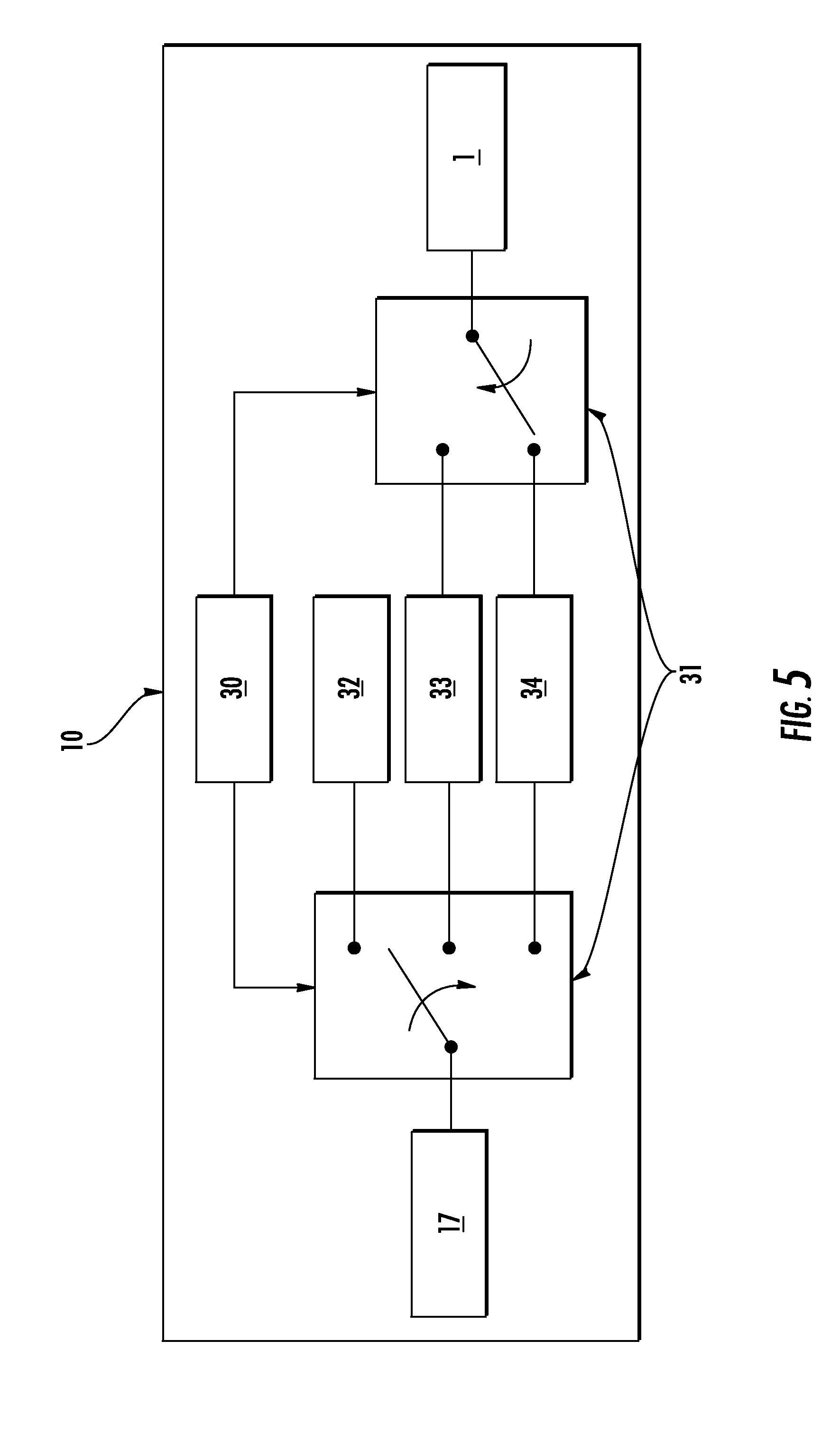
[0021] FIG. 5 schematically depicts the deactivation of an EAS tag.
DETAILED DESCRIPTION
[0022] The present invention embraces a multifunction cordless indicia reader. The functions available are: (i) indicia reading, (ii) wireless charging, and (iii) electronic article surveillance (EAS) deactivation. The wireless charging and EAS deactivation functions are facilitated by a multifunction coil.
[0023] In an exemplary embodiment shown in FIG. 1, the multifunction coil 1 contains an insulated conductor arranged in planar, concentric turns (i.e., planar spiral coil). The multifunction coil's conductor 2 may be thin (e.g., 0.3 millimeter diameter). The conductor may be made from copper or another conducting material and coated with an insulating film. The diameter of the conductor is chosen to handle a sustained power level experienced with wireless charging (e.g., 5 watts). The coil is also designed to transmit pulsed energy efficiently for EAS deactivation. An exemplary embodiment of the multifunction coil for wireless charging and EAS deactivation has 15 turns, resulting in a coil inductance of about 9 to 11 micro-Henrys. The resistance of the coil is low and is about 0.2 ohm at 25 degree Celsius.
[0024] The coil's physical design facilitates the integration within a handle section of the hand-held cordless indicia reader's hand-supportable housing. For this integration, the coil shown in FIG. 1 may have a coil-length 3, coil-width 4, and coil-thickness 5 of approximately 48.times.32.times.1 millimeters (mm), respectively. As shown in FIG. 2, the cordless indicia reader 10 has a hand-supportable housing with a handle 11 for an operator to hold like a gun. A scan button 12 is integrated with the housing to allow the operator to activate (i.e., trigger) indicia-reading by pressing this button (i.e., pulling the trigger). The multifunction coil 1 may be positioned inside the hand-supportable housing at the base of the handle.
[0025] The multifunction coil supports wireless charging (i.e., inductive charging). This form of charging uses an electromagnetic field to transfer energy between two coils through magnetic induction. As shown in FIG. 3, the first of these coils 14 may be integrated into a charging station as part of a host system 15 (e.g., a point-of-sale system). This coil is known as the host charging coil 14 and serves as the primary coil (i.e., transmitting coil) in a coil pair, acting as a kind of transformer. The second coil of this coil pair is the multifunction coil 1 and is integrated with the cordless indicia reader 10. This coil serves as the secondary coil (i.e., receiving coil) in the transformer coil pair and receives energy wirelessly. When the two coils are in proximity (e.g., 0 to 5 millimeters) the coils couple through their magnetic fields (i.e., mutual induction) and energy from the primary coil 14 will be transferred to the secondary coil 1. A charging source 16 connected to the host charging coil 14 excites the host charging coil 14 with an alternating current at a frequency suitable for wireless charging (e.g., 110 to 205 kilohertz [KHz]). The electromagnetic charging signal may comport with a wireless charging standard and, as such, this application hereby incorporates by reference the Wireless Power Consortium's Qi (WPC-Qi) specifications for wireless charging (i.e., WPC-Qi Wireless Power Specification, version 1.1.2, June 2013) in its entirety. A battery module 17 connected to the multifunction coil 1 stores the wirelessly transferred energy in an energy storage component (e.g., battery).
[0026] The multifunction coil also supports electronic article surveillance (EAS) tag deactivation. EAS is a scheme for preventing the unauthorized removal of an item from a controlled area (e.g., shoplifting). An activated EAS tag is affixed to the item in a way that is difficult for a potential thief to detect, tamper with, or remove. A gateway sensor that can sense the activated EAS tag is positioned in such a way as to scan all traffic into and out of the controlled area. When an active tag is detected, an alarm may sound to alert personnel of the attempted theft.
[0027] A variety of EAS tags exist, each with their own scanning/sensing scheme. Radio frequency (RF) EAS tags are especially popular. These EAS tags may be soft tags integrated within item packaging or integrated in package labels. The tags operate based on an inductive-capacitive (LC) resonant (i.e., tank) circuit. The tank circuit may have a resonance in the range of 7.5 to 8.8 megahertz (MHz), and this resonance may be detected during the gateway sensor's scan as a narrow-band energy loss. To deactivate the tag, this resonance may be destroyed by subjecting it to a large energy RF pulse at or near the resonant frequency of the EAS tag. The energy in this pulse open-circuits a fuse (i.e., blows the fuse) in the LC tank circuit. Alternatively, the capacitor in the LC tank circuit may be damaged as a result of the deactivation pulse and, in this way, serves as a kind of fuse. Whatever the case, the RF pulse destroys the LC resonance and deactivates the tag. Deactivated tags may pass through the gateway detector triggering no alarms.
[0028] The cordless indicia reader with the multipurpose coil may deactivate EAS tags. An EAS-tag deactivation signal may be generated by an EAS-deactivation module in the cordless indicia reader when an active tag is sensed or after some condition is met (e.g., a successful barcode scan). As shown in FIG. 4, the deactivation signal (i.e., RF pulse) 20 may be transmitted by the multipurpose coil 1 and received by the EAS tag 21. The energy in the pulse is sufficient to deactivate the EAS-tag 21. Because the tag may be resonant at the deactivation signal's frequency, the range for deactivation can be as much as 110 millimeters. This range may vary, however, depending on the energy of the EAS-deactivation signal.
[0029] A schematic of the cordless indicia reader's plurality of modules and their interconnections is shown in FIG. 5. A control module 30 is configured to send signals to a switching module 31 configured with one or more electrical switches to electrically interconnect (i.e., enable) the modules and enable a particular mode of operation. The various modes of operation include: (i) an indicia reading mode for reading indicia (e.g., scanning barcodes), (ii) a wireless charging mode for receiving energy to charge an integrated energy storage device (e.g., battery), and (iii) an EAS-deactivation mode for transmitting energy to deactivate an EAS tag (e.g., soft, RF tags). A battery module 17 contains an energy storage device and may include circuitry for filtering and regulation. The battery module supplies energy to power the other modules to enable their function. An indicia-reading module 32 performs all the functions of indicia reading. This mode of operation is enabled when the scan button 12 is pressed.
[0030] The multifunction coil 1 can be switched between the charging module 33 and the EAS deactivation module 34 depending on the mode of operation. In the wireless charging mode, the switching module is configured to connect the battery module 17 with the charging module 33, which in turn is connected to the multifunction coil 1. The charging module is configured with circuitry to adjust the voltage and current levels of an electromagnetic charging signal in order to facilitate charging of the energy storage device in the battery module 17. The wireless-charging mode may be the default mode of the indicia reader.
[0031] In the EAS-deactivation mode, the switching module is configured to electrically interconnect the battery module 17 and the EAS-deactivation module 34. In addition the EAS-deactivation module is connected, via the switching module, with the multifunction coil 1. This mode of operation may be triggered to occur when the scanner senses an activated EAS tag or after an indicia is read. In either case, in this mode of operation, the EAS-deactivation module generates an EAS-deactivation signal. This signal may contain at least one RF pulse. This RF pulse has the characteristics necessary and sufficient for EAS tag deactivation (e.g., 7.5-8.8 MHz). The multifunction coil is used to transmit the pulse wirelessly to deactivate the EAS tag.
[0032] To supplement the present disclosure, this application incorporates entirely by reference the following commonly assigned patents, patent application publications, and patent applications: [0033] U.S. Pat. No. 6,832,725; U.S. Pat. No. 7,128,266; [0034] U.S. Pat. No. 7,159,783; U.S. Pat. No. 7,413,127; [0035] U.S. Pat. No. 7,726,575; U.S. Pat. No. 8,294,969; [0036] U.S. Pat. No. 8,317,105; U.S. Pat. No. 8,322,622; [0037] U.S. Pat. No. 8,366,005; U.S. Pat. No. 8,371,507; [0038] U.S. Pat. No. 8,376,233; U.S. Pat. No. 8,381,979; [0039] U.S. Pat. No. 8,390,909; U.S. Pat. No. 8,408,464; [0040] U.S. Pat. No. 8,408,468; U.S. Pat. No. 8,408,469; [0041] U.S. Pat. No. 8,424,768; U.S. Pat. No. 8,448,863; [0042] U.S. Pat. No. 8,457,013; U.S. Pat. No. 8,459,557; [0043] U.S. Pat. No. 8,469,272; U.S. Pat. No. 8,474,712; [0044] U.S. Pat. No. 8,479,992; U.S. Pat. No. 8,490,877; [0045] U.S. Pat. No. 8,517,271; U.S. Pat. No. 8,523,076; [0046] U.S. Pat. No. 8,528,818; U.S. Pat. No. 8,544,737; [0047] U.S. Pat. No. 8,548,242; U.S. Pat. No. 8,548,420; [0048] U.S. Pat. No. 8,550,335; U.S. Pat. No. 8,550,354; [0049] U.S. Pat. No. 8,550,357; U.S. Pat. No. 8,556,174; [0050] U.S. Pat. No. 8,556,176; U.S. Pat. No. 8,556,177; [0051] U.S. Pat. No. 8,559,767; U.S. Pat. No. 8,599,957; [0052] U.S. Pat. No. 8,561,895; U.S. Pat. No. 8,561,903; [0053] U.S. Pat. No. 8,561,905; U.S. Pat. No. 8,565,107; [0054] U.S. Pat. No. 8,571,307; U.S. Pat. No. 8,579,200; [0055] U.S. Pat. No. 8,583,924; U.S. Pat. No. 8,584,945; [0056] U.S. Pat. No. 8,587,595; U.S. Pat. No. 8,587,697; [0057] U.S. Pat. No. 8,588,869; U.S. Pat. No. 8,590,789; [0058] U.S. Pat. No. 8,596,539; U.S. Pat. No. 8,596,542; [0059] U.S. Pat. No. 8,596,543; U.S. Pat. No. 8,599,271; [0060] U.S. Pat. No. 8,599,957; U.S. Pat. No. 8,600,158; [0061] U.S. Pat. No. 8,600,167; U.S. Pat. No. 8,602,309; [0062] U.S. Pat. No. 8,608,053; U.S. Pat. No. 8,608,071; [0063] U.S. Pat. No. 8,611,309; U.S. Pat. No. 8,615,487; [0064] U.S. Pat. No. 8,616,454; U.S. Pat. No. 8,621,123; [0065] U.S. Pat. No. 8,622,303; U.S. Pat. No. 8,628,013; [0066] U.S. Pat. No. 8,628,015; U.S. Pat. No. 8,628,016; [0067] U.S. Pat. No. 8,629,926; U.S. Pat. No. 8,630,491; [0068] U.S. Pat. No. 8,635,309; U.S. Pat. No. 8,636,200; [0069] U.S. Pat. No. 8,636,212; U.S. Pat. No. 8,636,215; [0070] U.S. Pat. No. 8,636,224; U.S. Pat. No. 8,638,806; [0071] U.S. Pat. No. 8,640,958; U.S. Pat. No. 8,640,960; [0072] U.S. Pat. No. 8,643,717; U.S. Pat. No. 8,646,692; [0073] U.S. Pat. No. 8,646,694; U.S. Pat. No. 8,657,200; [0074] U.S. Pat. No. 8,659,397; U.S. Pat. No. 8,668,149; [0075] U.S. Pat. No. 8,678,285; U.S. Pat. No. 8,678,286; [0076] U.S. Pat. No. 8,682,077; U.S. Pat. No. 8,687,282; [0077] U.S. Pat. No. 8,692,927; U.S. Pat. No. 8,695,880; [0078] U.S. Pat. No. 8,698,949; U.S. Pat. No. 8,717,494; [0079] U.S. Pat. No. 8,717,494; U.S. Pat. No. 8,720,783; [0080] U.S. Pat. No. 8,723,804; U.S. Pat. No. 8,723,904; [0081] U.S. Pat. No. 8,727,223; U.S. Pat. No. D702,237; [0082] International Publication No. 2013/163789; [0083] International Publication No. 2013/173985; [0084] International Publication No. 2014/019130; [0085] U.S. Patent Application Publication No. 2008/0185432; [0086] U.S. Patent Application Publication No. 2009/0134221; [0087] U.S. Patent Application Publication No. 2010/0177080; [0088] U.S. Patent Application Publication No. 2010/0177076; [0089] U.S. Patent Application Publication No. 2010/0177707; [0090] U.S. Patent Application Publication No. 2010/0177749; [0091] U.S. Patent Application Publication No. 2011/0202554; [0092] U.S. Patent Application Publication No. 2012/0111946; [0093] U.S. Patent Application Publication No. 2012/0138685; [0094] U.S. Patent Application Publication No. 2012/0168511; [0095] U.S. Patent Application Publication No. 2012/0168512; [0096] U.S. Patent Application Publication No. 2012/0193407; [0097] U.S. Patent Application Publication No. 2012/0193423; [0098] U.S. Patent Application Publication No. 2012/0203647; [0099] U.S. Patent Application Publication No. 2012/0223141; [0100] U.S. Patent Application Publication No. 2012/0228382; [0101] U.S. Patent Application Publication No. 2012/0248188; [0102] U.S. Patent Application Publication No. 2013/0043312; [0103] U.S. Patent Application Publication No. 2013/0056285; [0104] U.S. Patent Application Publication No. 2013/0070322; [0105] U.S. Patent Application Publication No. 2013/0075168; [0106] U.S. Patent Application Publication No. 2013/0082104; [0107] U.S. Patent Application Publication No. 2013/0175341; [0108] U.S. Patent Application Publication No. 2013/0175343; [0109] U.S. Patent Application Publication No. 2013/0200158; [0110] U.S. Patent Application Publication No. 2013/0214048; [0111] U.S. Patent Application Publication No. 2013/0256418; [0112] U.S. Patent Application Publication No. 2013/0257744; [0113] U.S. Patent Application Publication No. 2013/0257759; [0114] U.S. Patent Application Publication No. 2013/0270346; [0115] U.S. Patent Application Publication No. 2013/0278425; [0116] U.S. Patent Application Publication No. 2013/0287258; [0117] U.S. Patent Application Publication No. 2013/0292474; [0118] U.S. Patent Application Publication No. 2013/0292475; [0119] U.S. Patent Application Publication No. 2013/0292477; [0120] U.S. Patent Application Publication No. 2013/0293539; [0121] U.S. Patent Application Publication No. 2013/0293540; [0122] U.S. Patent Application Publication No. 2013/0306728; [0123] U.S. Patent Application Publication No. 2013/0306730; [0124] U.S. Patent Application Publication No. 2013/0306731; [0125] U.S. Patent Application Publication No. 2013/0306734; [0126] U.S. Patent Application Publication No. 2013/0307964; [0127] U.S. Patent Application Publication No. 2013/0308625; [0128] U.S. Patent Application Publication No. 2013/0313324; [0129] U.S. Patent Application Publication No. 2013/0313325; [0130] U.S. Patent Application Publication No. 2013/0313326; [0131] U.S. Patent Application Publication No. 2013/0327834; [0132] U.S. Patent Application Publication No. 2013/0341399; [0133] U.S. Patent Application Publication No. 2013/0342717; [0134] U.S. Patent Application Publication No. 2014/0001267; [0135] U.S. Patent Application Publication No. 2014/0002828; [0136] U.S. Patent Application Publication No. 2014/0008430; [0137] U.S. Patent Application Publication No. 2014/0008439; [0138] U.S. Patent Application Publication No. 2014/0021256; [0139] U.S. Patent Application Publication No. 2014/0025584; [0140] U.S. Patent Application Publication No. 2014/0027518; [0141] U.S. Patent Application Publication No. 2014/0034723; [0142] U.S. Patent Application Publication No. 2014/0034734; [0143] U.S. Patent Application Publication No. 2014/0036848; [0144] U.S. Patent Application Publication No. 2014/0039693; [0145] U.S. Patent Application Publication No. 2014/0042814; [0146] U.S. Patent Application Publication No. 2014/0049120; [0147] U.S. Patent Application Publication No. 2014/0049635; [0148] U.S. Patent Application Publication No. 2014/0061305; [0149] U.S. Patent Application Publication No. 2014/0061306; [0150] U.S. Patent Application Publication No. 2014/0061307; [0151] U.S. Patent Application Publication No. 2014/0063289; [0152] U.S. Patent Application Publication No. 2014/0066136; [0153] U.S. Patent Application Publication No. 2014/0067692; [0154] U.S. Patent Application Publication No. 2014/0070005; [0155] U.S. Patent Application Publication No. 2014/0071840; [0156] U.S. Patent Application Publication No. 2014/0074746; [0157] U.S. Patent Application Publication No. 2014/0075846; [0158] U.S. Patent Application Publication No. 2014/0076974; [0159] U.S. Patent Application Publication No. 2014/0078341; [0160] U.S. Patent Application Publication No. 2014/0078342; [0161] U.S. Patent Application Publication No. 2014/0078345; [0162] U.S. Patent Application Publication No. 2014/0084068; [0163] U.S. Patent Application Publication No. 2014/0086348; [0164] U.S. Patent Application Publication No. 2014/0097249; [0165] U.S. Patent Application Publication No. 2014/0098284; [0166] U.S. Patent Application Publication No. 2014/0098792; [0167] U.S. Patent Application Publication No. 2014/0100774; [0168] U.S. Patent Application Publication No. 2014/0100813; [0169] U.S. Patent Application Publication No. 2014/0103115; [0170] U.S. Patent Application Publication No. 2014/0104413; [0171] U.S. Patent Application Publication No. 2014/0104414; [0172] U.S. Patent Application Publication No. 2014/0104416; [0173] U.S. Patent Application Publication No. 2014/0104451; [0174] U.S. Patent Application Publication No. 2014/0106594; [0175] U.S. Patent Application Publication No. 2014/0106725; [0176] U.S. Patent Application Publication No. 2014/0108010; [0177] U.S. Patent Application Publication No. 2014/0108402; [0178] U.S. Patent Application Publication No. 2014/0108682; [0179] U.S. Patent Application Publication No. 2014/0110485; [0180] U.S. Patent Application Publication No. 2014/0114530; [0181] U.S. Patent Application Publication No. 2014/0124577; [0182] U.S. Patent Application Publication No. 2014/0124579; [0183] U.S. Patent Application Publication No. 2014/0125842; [0184] U.S. Patent Application Publication No. 2014/0125853; [0185] U.S. Patent Application Publication No. 2014/0125999; [0186] U.S. Patent Application Publication No. 2014/0129378; [0187] U.S. patent application Ser. No. 13/367,978 for a Laser Scanning Module Employing An Elastomeric U-Hinge Based Laser Scanning Assembly, filed Feb. 7, 2012 (Feng et al.); [0188] U.S. patent application Ser. No. 29/436,337 for an Electronic Device, filed Nov. 5, 2012 (Fitch et al.); [0189] U.S. patent application Ser. No. 13/736,139 for an Electronic Device Enclosure, filed Jan. 8, 2013 (Chaney); [0190] U.S. patent application Ser. No. 13/771,508 for an Optical Redirection Adapter, filed Feb. 20, 2013 (Anderson); [0191] U.S. patent application Ser. No. 13/780,356 for a Mobile Device Having Object-Identification Interface, filed Feb. 28, 2013 (Samek et al.); [0192] U.S. patent application Ser. No. 13/852,097 for a System and Method for Capturing and Preserving Vehicle Event Data, filed Mar. 28, 2013 (Barker et al.); [0193] U.S. patent application Ser. No. 13/902,110 for a System and Method for Display of Information Using a Vehicle-Mount Computer, filed May 24, 2013 (Hollifield); [0194] U.S. patent application Ser. No. 13/902,144, for a System and Method for Display of Information Using a Vehicle-Mount Computer, filed May 24, 2013 (Chamberlin); [0195] U.S. patent application Ser. No. 13/902,242 for a System For Providing A Continuous Communication Link With A Symbol Reading Device, filed May 24, 2013 (Smith et al.); [0196] U.S. patent application Ser. No. 13/912,262 for a Method of Error Correction for 3D Imaging Device, filed Jun. 7, 2013 (Jovanovski et al.); [0197] U.S. patent application Ser. No. 13/912,702 for a System and Method for Reading Code Symbols at Long Range Using Source Power Control, filed Jun. 7, 2013 (Xian et al.); [0198] U.S. patent application Ser. No. 29/458,405 for an Electronic Device, filed Jun. 19, 2013 (Fitch et al.); [0199] U.S. patent application Ser. No. 13/922,339 for a System and Method for Reading Code Symbols Using a Variable Field of View, filed Jun. 20, 2013 (Xian et al.); [0200] U.S. patent application Ser. No. 13/927,398 for a Code Symbol Reading System Having Adaptive Autofocus, filed Jun. 26, 2013 (Todeschini); [0201] U.S. patent application Ser. No. 13/930,913 for a Mobile Device Having an Improved User Interface for Reading Code Symbols, filed Jun. 28, 2013 (Gelay et al.); [0202] U.S. patent application Ser. No. 29/459,620 for an Electronic Device Enclosure, filed Jul. 2, 2013 (London et al.); [0203] U.S. patent application Ser. No. 29/459,681 for an Electronic Device Enclosure, filed Jul. 2, 2013 (Chaney et al.); [0204] U.S. patent application Ser. No. 13/933,415 for an Electronic Device Case, filed Jul. 2, 2013 (London et al.); [0205] U.S. patent application Ser. No. 29/459,785 for a Scanner and Charging Base, filed Jul. 3, 2013 (Fitch et al.); [0206] U.S. patent application Ser. No. 29/459,823 for a Scanner, filed Jul. 3, 2013 (Zhou et al.); [0207] U.S. patent application Ser. No. 13/947,296 for a System and Method for Selectively Reading Code Symbols, filed Jul. 22, 2013 (Rueblinger et al.); [0208] U.S. patent application Ser. No. 13/950,544 for a Code Symbol Reading System Having Adjustable Object Detection, filed Jul. 25, 2013 (Jiang); [0209] U.S. patent application Ser. No. 13/961,408 for a Method for Manufacturing Laser Scanners, filed Aug. 7, 2013 (Saber et al.); [0210] U.S. patent application Ser. No. 14/018,729 for a Method for Operating a Laser Scanner, filed Sep. 5, 2013 (Feng et al.); [0211] U.S. patent application Ser. No. 14/019,616 for a Device Having Light Source to Reduce Surface Pathogens, filed Sep. 6, 2013 (Todeschini); [0212] U.S. patent application Ser. No. 14/023,762 for a Handheld Indicia Reader Having Locking Endcap, filed Sep. 11, 2013 (Gannon); [0213] U.S. patent application Ser. No. 14/035,474 for Augmented-Reality Signature Capture, filed Sep. 24, 2013 (Todeschini); [0214] U.S. patent application Ser. No. 29/468,118 for an Electronic Device Case, filed Sep. 26, 2013 (Oberpriller et al.); [0215] U.S. patent application Ser. No. 14/047,896 for Terminal Having Illumination and Exposure Control filed Oct. 7, 2013 (Jovanovski et al.); [0216] U.S. patent application Ser. No. 14/053,175 for Imaging Apparatus Having Imaging Assembly, filed Oct. 14, 2013 (Barber); [0217] U.S. patent application Ser. No. 14/055,234 for Dimensioning System, filed Oct. 16, 2013 (Fletcher); [0218] U.S. patent application Ser. No. 14/053,314 for Indicia Reader, filed Oct. 14, 2013 (Huck); [0219] U.S. patent application Ser. No. 14/065,768 for Hybrid System and Method for Reading Indicia, filed Oct. 29, 2013 (Meier et al.); [0220] U.S. patent application Ser. No. 14/074,746 for Self-Checkout Shopping System, filed Nov. 8, 2013 (Hejl et al.); [0221] U.S. patent application Ser. No. 14/074,787 for Method and System for Configuring Mobile Devices via NFC Technology, filed Nov. 8, 2013 (Smith et al.); [0222] U.S. patent application Ser. No. 14/087,190 for Optimal Range Indicators for Bar Code Validation, filed Nov. 22, 2013 (Hejl); [0223] U.S. patent application Ser. No. 14/094,087 for Method and System for Communicating Information in an Digital Signal, filed Dec. 2, 2013 (Peake et al.); [0224] U.S. patent application Ser. No. 14/101,965 for High Dynamic-Range Indicia Reading System, filed Dec. 10, 2013 (Xian); [0225] U.S. patent application Ser. No. 14/118,400 for Indicia Decoding Device with Security Lock, filed Nov. 18, 2013 (Liu); [0226] U.S. patent application Ser. No. 14/150,393 for Incicia-reader Having Unitary Construction Scanner, filed Jan. 8, 2014 (Colavito et al.); [0227] U.S. patent application Ser. No. 14/154,207 for Laser Barcode Scanner, filed Jan. 14, 2014 (Hou et al.); [0228] U.S. patent application Ser. No. 14/154,915 for Laser Scanning Module Employing a Laser Scanning Assembly having Elastomeric Wheel Hinges, filed Jan. 14, 2014 (Havens et al.);
[0229] U.S. patent application Ser. No. 14/158,126 for Methods and Apparatus to Change a Feature Set on Data Collection Devices, filed Jan. 17, 2014 (Berthiaume et al.); [0230] U.S. patent application Ser. No. 14/159,074 for Wireless Mesh Point Portable Data Terminal, filed Jan. 20, 2014 (Wang et al.); [0231] U.S. patent application Ser. No. 14/159,509 for MMS Text Messaging for Hand Held Indicia Reader, filed Jan. 21, 2014 (Kearney); [0232] U.S. patent application Ser. No. 14/159,603 for Decodable Indicia Reading Terminal with Optical Filter, filed Jan. 21, 2014 (Ding et al.); [0233] U.S. patent application Ser. No. 14/160,645 for Decodable Indicia Reading Terminal with Indicia Analysis Functionality, filed Jan. 22, 2014 (Nahill et al.); [0234] U.S. patent application Ser. No. 14/161,875 for System and Method to Automatically Discriminate Between Different Data Types, filed Jan. 23, 2014 (Wang); [0235] U.S. patent application Ser. No. 14/165,980 for System and Method for Measuring Irregular Objects with a Single Camera filed Jan. 28, 2014 (Li et al.); [0236] U.S. patent application Ser. No. 14/166,103 for Indicia Reading Terminal Including Optical Filter filed Jan. 28, 2014 (Lu et al.); [0237] U.S. patent application Ser. No. 14/176,417 for Devices and Methods Employing Dual Target Auto Exposure filed Feb. 10, 2014 (Meier et al.); [0238] U.S. patent application Ser. No. 14/187,485 for Indicia Reading Terminal with Color Frame Processing filed Feb. 24, 2014 (Ren et al.); [0239] U.S. patent application Ser. No. 14/200,405 for Indicia Reader for Size-Limited Applications filed Mar. 7, 2014 (Feng et al.); [0240] U.S. patent application Ser. No. 14/222,994 for Method and Apparatus for Reading Optical Indicia Using a Plurality of Data filed Mar. 24, 2014 (Smith et al.); [0241] U.S. patent application Ser. No. 14/230,322 for Focus Module and Components with Actuator filed Mar. 31, 2014 (Feng et al.); [0242] U.S. patent application Ser. No. 14/231,898 for Hand-Mounted Indicia-Reading Device with Finger Motion Triggering filed Apr. 1, 2014 (Van Horn et al.); [0243] U.S. patent application Ser. No. 14/249,497 for Terminal Having Plurality of Operating Modes filed Apr. 10, 2014, Grunow et al.); [0244] U.S. patent application Ser. No. 14/250,923 for Reading Apparatus Having Partial Frame Operating Mode filed Apr. 11, 2014, (Deng et al.); [0245] U.S. patent application Ser. No. 14/257,174 for Imaging Terminal Having Data Compression filed Apr. 21, 2014, (Barber et al.); [0246] U.S. patent application Ser. No. 14/257,364 for Docking System and Method Using Near Field Communication filed Apr. 21, 2014, (Showering); [0247] U.S. patent application Ser. No. 14/264,173 for Autofocus Lens System for Indicia Readers filed Apr. 29, 2014, (Ackley et al.); [0248] U.S. patent application Ser. No. 14/274,858 for Mobile Printer with Optional Battery Accessory filed May 12, 2014, (Marty et al.); [0249] U.S. patent application Ser. No. 14/342,544 for Imaging Based Barcode Scanner Engine with Multiple Elements Supported on a Common Printed Circuit Board filed Mar. 4, 2014 (Liu et al.); [0250] U.S. patent application Ser. No. 14/342,551 for Terminal Having Image Data Format Conversion filed Mar. 4, 2014 (Lui et al.); [0251] U.S. patent application Ser. No. 14/345,735 for Optical Indicia Reading Terminal with Combined Illumination filed Mar. 19, 2014 (Ouyang); [0252] U.S. patent application Ser. No. 29/486,759 for an Imaging Terminal, filed Apr. 2, 2014 (Oberpriller et al.); and [0253] U.S. patent application Ser. No. 14/355,613 for Optical Indicia Reading Terminal with Color Image Sensor filed May 1, 2014, (Lu et al.).
[0254] In the specification and/or figures, typical embodiments of the invention have been disclosed. The present invention is not limited to such exemplary embodiments. The use of the term "and/or" includes any and all combinations of one or more of the associated listed items. The figures are schematic representations and so are not necessarily drawn to scale. Unless otherwise noted, specific terms have been used in a generic and descriptive sense and not for purposes of limitation.
* * * * *
D00000
D00001
D00002
D00003
D00004
D00005
XML
uspto.report is an independent third-party trademark research tool that is not affiliated, endorsed, or sponsored by the United States Patent and Trademark Office (USPTO) or any other governmental organization. The information provided by uspto.report is based on publicly available data at the time of writing and is intended for informational purposes only.
While we strive to provide accurate and up-to-date information, we do not guarantee the accuracy, completeness, reliability, or suitability of the information displayed on this site. The use of this site is at your own risk. Any reliance you place on such information is therefore strictly at your own risk.
All official trademark data, including owner information, should be verified by visiting the official USPTO website at www.uspto.gov. This site is not intended to replace professional legal advice and should not be used as a substitute for consulting with a legal professional who is knowledgeable about trademark law.