Pyrotechnic Device
Runck; Andreas
U.S. patent application number 14/682195 was filed with the patent office on 2015-12-31 for pyrotechnic device. This patent application is currently assigned to Drew Defense GmbH. The applicant listed for this patent is Drew Defense GmbH. Invention is credited to Andreas Runck.
| Application Number | 20150377598 14/682195 |
| Document ID | / |
| Family ID | 52823996 |
| Filed Date | 2015-12-31 |


| United States Patent Application | 20150377598 |
| Kind Code | A1 |
| Runck; Andreas | December 31, 2015 |
PYROTECHNIC DEVICE
Abstract
Parachutes for signalling rockets, for example, open in a jerky manner, as a result of which the suspension lines (13) are exposed to a heavy load. The invention envisages two suspension lines (14) configured in an extensible, particularly rubber-band-like manner, as a result of which the initially effective parachute surface area is reduced, which causes the parachute canopy (12) of the parachute (10) to open more slowly than with previous parachutes (10), which in turn reduces the opening jerk of the parachute (10). In this way, the suspension lines (13, 14) in particular, but also the parachute canopy (12) of the parachute (10), are subject to less load.
| Inventors: | Runck; Andreas; (Bremerhaven, DE) | ||||||||||
| Applicant: |
|
||||||||||
|---|---|---|---|---|---|---|---|---|---|---|---|
| Assignee: | Drew Defense GmbH Bremerhaven DE |
||||||||||
| Family ID: | 52823996 | ||||||||||
| Appl. No.: | 14/682195 | ||||||||||
| Filed: | April 9, 2015 |
| Current U.S. Class: | 102/348 |
| Current CPC Class: | F42B 10/56 20130101; F42B 4/28 20130101; B64D 17/24 20130101; F42B 4/12 20130101 |
| International Class: | F42B 4/12 20060101 F42B004/12 |
Foreign Application Data
| Date | Code | Application Number |
|---|---|---|
| Jun 25, 2014 | DE | 102014009168.6 |
| Nov 18, 2014 | DE | 102014016951.0 |
Claims
1. A pyrotechnic device having a rocket or a projectile, a parachute (10; 25; 31) with parachute lines and at least one signalling, illumination and/or observational means assigned to the parachute (10; 25; 31), wherein the at least one parachute line is more extensible than at least one other parachute line.
2. The pyrotechnic device according to claim 1, wherein the extensibility of each extensible or more extensible parachute line is at least twice as great as the extensibility of the at least one, preferably all, other parachute lines and/or each extensible or more extensible parachute line is extensible by at least 30% of its starting length.
3. The pyrotechnic device according to claim 1, wherein the at least one other parachute line is not or at least scarcely extensible during deployment of the parachute (10; 25; 31).
4. The pyrotechnic device according to claim 1, wherein the or each extensible or more extensible parachute line is extensible at least to such an extent that its length can be increased by the diameter, the greatest width or the diagonal of an outline surface area of the parachute (10; 25; 31), particularly of a top surface (16) or a cut piece of a parachute canopy (12; 26; 32).
5. The pyrotechnic device according to claim 1, wherein one or at least two adjacent parachute lines exhibit a greater extensibility than the other parachute lines.
6. The pyrotechnic device according to claim 1, wherein the extension of all parachute lines, in particular the extension of the extensible or more extensible parachute lines, falls in the elastic range.
7. The pyrotechnic device according to claim 1, wherein the elasticity of each extensible or more extensible parachute line is the same, the elasticity of the or of each extensible or more extensible parachute line is preferably such that when the parachute (10; 25; 31) or the parachute canopy (12; 26; 32) is completely opened, all parachute lines are at least the same length.
8. The pyrotechnic device according to claim 1, wherein the at least one extensible or more extensible parachute line is formed from at least one rubber-band-like strand, in particular a rubber band, and the at least one inextensible or less extensible parachute line is formed from a rope, preferably a braided or woven rope.
9. The pyrotechnic device according to claim 4, wherein the top surface (16) or the cut piece of the parachute canopy (12; 26; 32) has a preferably round or polygonal outline surface area, a periphery (17) of the top surface (16) is preferably surrounded by a collar (19), wherein a free lower periphery of the collar (19) exhibits tails (22) and one end of a parachute line is fastened to a tip (23) of each tail (22), the extensible or more extensible parachute lines are preferably fastened to the tips (23) of two adjacent tails (22).
10. The pyrotechnic device according to claim 1, characterized in that the parachute lines are suspension lines (13; 14; 28; 29; 34; 35).
11. The pyrotechnic device according to claim 10, wherein lower ends of the suspension lines (13, 14) opposite the ends of all suspension lines (13, 14) fastened to the tips (23) of the tails (22) of the collar (19) of the parachute canopy (12) are brought together at a connection point (24) and the signalling, illumination and/or observational means or an upper end of a further parachute line carrying the signalling, illumination and/or observational means, preferably a tethering line (15), is fastened to the connection point (24), wherein the additional parachute line or the tethering line (15) in particular is extensible, particularly elastically extensible.
Description
STATEMENT OF RELATED APPLICATIONS
[0001] This patent application claims priority on and the benefit of German Patent Application No. DE 10 2014 009 168.6 having a filing date of 25 Jun. 2014 and German Patent Application No. DE 10 2014 016 951.0 having a filing date of 18 Nov. 2014.
BACKGROUND OF THE INVENTION
[0002] 1. Technical Field
[0003] The invention relates to a pyrotechnic device having a rocket or a projectile, a parachute with parachute lines, and at least one signalling, illumination and/or observational means assigned to the parachute.
[0004] 2. Prior Art
[0005] The pyrotechnic devices referred to here are hand-fired parachute rockets and also fired parachute cartridges or parachute munitions with signalling means, illumination means and/or observational means. The observational means may be cameras, sensors or also measuring probes. The signalling, illumination or observational means along with a parachute assigned to each of them are fired up or on a ballistics trajectory by the rockets or munitions. Thereafter, the signalling, illumination and/or observational means fall slowly to earth hanging from the parachute.
[0006] With known pyrotechnic devices of this kind, the signalling, illumination and/or observational means are directly connected to the parachute lines, wherein the parachute lines are formed from ropes or other threads with no or no significant extensibility. Because the parachute lines are either inextensible or only slightly extensible, the parachute is completely effectively deployed quickly and immediately, which leads to a jerky deceleration of the signalling, illumination and/or observational means. The loads on the parachute lines, but also on the parachute canopy, are correspondingly great. This can lead to the failure of the parachute, as a result of which the signalling, illumination and/or observational means fall to the ground unbraked and therefore very quickly. So that the risks described can be reliably avoided, the parachute lines must have correspondingly thick dimensions, which reduces the weight of the parachute to the detriment of its load capacity, namely of the signalling, illumination and/or observational means. This requires a correspondingly large accommodating space in the pyrotechnic device.
BRIEF SUMMARY OF THE INVENTION
[0007] Based on the above, the problem addressed by the invention is that of developing a pyrotechnic device of the kind referred to above, such that the risk of affecting the parachute detrimentally, particularly during the opening or deployment phase of the parachute, is removed or at least significantly reduced in a simple, space-saving and cost-effective manner.
[0008] A pyrotechnic device for solving this problem is a pyrotechnic device having a rocket or a projectile, a parachute with parachute lines and at least one signalling, illumination and/or observational means assigned to the parachute, characterized in that at least one parachute line is more extensible than at least one other parachute line. According to this, at least one of the parachute lines is extensible and/or more extensible than the other parachute lines. In particular, only at least one parachute line is extensible, while at least one or all the other parachute lines are inextensible or virtually inextensible. The at least one extensible or more extensible parachute line means that the parachute is not immediately decelerated with the full braking effect and/or opens more slowly. The full effectiveness of the parachute, particularly of its canopy, only comes into play in a slow, time-delayed manner. The effective parachute surface area is initially reduced by the preferably rubber-band-like elongation of the at least one extensible parachute line. This initially leads only to a slight delay in the dropping speed of the parachute with the signalling, illumination and/or observational means suspended therefrom. The at least one extensible or more extensible parachute line then contracts little by little, preferably continuously, due to the reducing fall velocity, as a result of which the parachute, in particular the canopy thereof, only unfolds gradually, which means that the signalling, illumination and/or observational means fall to the ground consistently slowly over a prolonged period of time. As a result of this, the risk of the parachute, in particular the parachute canopy and/or the parachute lines, ripping can be removed or at least reduced without any substantial structural changes to the parachute and without additional space-requiring means. The parachute only adopts its planned orientation in which the extensible parachute lines have for the most part elastically contracted once again and all parachute lines are therefore roughly the same length or the non-extensible parachute lines are slightly longer than the extensible parachute lines after a delay. This planned orientation is only briefly referred to in the following as a "completely deployed parachute".
[0009] It is preferably provided that the extensibility of each extensible or more extensible parachute line is many times greater than the extensibility of at least one, preferably all, other parachute lines. It is thereby ensured that even when the other parachute lines are extensible--even if only slightly--the at least one more extensible parachute line can extend more and thereby contributes to the general, time-delayed entry into full effect or complete deployment of the parachute, in particular the parachute canopy.
[0010] Alternatively or in addition, it may be provided that each extensible or more extensible parachute line is extensible by at least 30% of its unloaded total length (starting length). In other words, this at least one parachute line can be extended elastically to at least 1.3 times its original length during the opening of the parachute. It is preferably provided that each extensible or more extensible parachute line can be extended to more than 1.5 times its starting length.
[0011] According to an advantageous embodiment of the invention, it may be provided that at least one of the other parachute lines is not or at least scarcely extensible during deployment of the parachute. Only the at least one extensible or more extensible parachute line then alters its length during the opening of the parachute, as a result of which there is an initial reduction in the effective parachute surface area, which substantially reduces the load in the overall parachute system due to a smaller opening jerk.
[0012] An advantageous possible embodiment of the device provides that the or that each extensible or more extensible parachute line is extensible at least to such an extent that its starting length can be increased by the diameter, the greatest width or the diagonal of an outline surface area of the parachute, particularly of the parachute canopy. In this way, the at least one extensible or more extensible parachute line can initially be extended so far that the surface area of the parachute canopy initially runs roughly in the longitudinal direction of the parachute lines or else parallel or slightly obliquely to the flight path of the parachute and is then continuously reoriented through the gradual elastic regression of the extension of the extensible parachute line or lines of the parachute or the parachute canopy until the parachute becomes completely effective, in particular the complete braking effect of the parachute canopy is achieved, at which the outline surface area of the parachute canopy then extends roughly at right angles transversely to the flight path.
[0013] In a preferred development of the device, it is provided that at least two adjacent parachute lines or, alternatively, two opposite parachute lines are extensible and/or have a greater extensibility than the other parachute lines. In this way, an initial orientation of the parachute canopy longitudinally to the parachute lines or in the flight direction is reliably carried out. The parachute canopy is practically pulled in the flight direction preferably by two non-extensible or only slightly extensible parachute lines, while a peripheral region of the parachute canopy is held in the opposite direction to the flight path by the extensible or more extensible parachute lines and the air forces occurring, as a result of which the parachute does not immediately open completely, but only little by little as the speed decreases.
[0014] It is preferably provided that the extension of all parachute lines, in particular the extension of the more extensible parachute lines, falls within the elastic region. It is thereby ensured that the initial extension, especially of the more extensible parachute lines, is gradually reversed again, at least for the most part, until the parachute is completely effective and/or completely opened or else the parachute canopy is deployed.
[0015] It is particularly advantageous if the elasticity of each extensible or more extensible parachute line is the same, preferably the elasticity of the or of each extensible or more extensible parachute line is such that when the parachute is completely open or the parachute canopy is completely deployed, all parachute lines are the same length or approximately the same length. This means that once the complete parachute braking effect has been achieved, the parachute lines act as in the case of traditional parachutes with all non-extensible or only equally slightly extensible parachute lines.
[0016] An advantageous possible embodiment of the invention envisages that the extensible or more extensible parachute lines are formed from at least one rubber-band-like strand, in particular a rubber band. By comparison, the parachute lines which are not or only slightly extensible are traditionally formed from a line or a rope, preferably a braided or woven rope, with virtually no elasticity. Through the formation of the extensible or more extensible parachute lines out of at least one rubber-band-like strand or else a rubber band, at least this one parachute line acquires an extensibility and elasticity that is substantially greater than in the case of the other parachute lines which are either not extensible at all or only to a negligibly small extent within the framework of the forces occurring, wherein an extension of this kind of the customary parachute lines lies below 1% of the starting length.
[0017] An advantageous possible development of the device envisages in the case of a parachute canopy with a top surface with a preferably round, polygonal or elliptical cross section and a collar surrounding the periphery of the top surface, that a free lower periphery of the collar exhibits tails and one end of a parachute line is fastened to a tip of each tail. With a parachute of this kind, the extensible or more extensible parachute lines are preferably fastened to the tips of two adjacent tails. This kind of parachute configuration has surprisingly proved particularly effective in connection with non-extensible or only slightly extensible parachute lines, on the one hand, and extensible or more extensible parachute lines, on the other. In this way, the delayed braking action of the parachute, in other words the lengthening of the time taken until the complete parachute canopy surface is available for deceleration, is brought about particularly reliably and as a result of this there is a reduction under all circumstances in the opening jerk occurring when the parachute is deployed.
[0018] Another possible embodiment of the device envisages connecting together the ends opposite the ends of the parachute lines fastened to the parachute canopy at a connection point. Either the signalling, illumination and/or observational means can be directly fastened at the connection point or also one end of another parachute line, for example a tethering line, which carries the signalling, illumination and/or observational means at the opposite end. In this case, the at least one further parachute line or tethering line, just as with a part of the parachute lines, may be extensible, preferably elastically extensible. This extensibility may, if necessary, be just as great as the extensible or more extensible parachute lines. Through a further parachute line or tethering line configured in this way, the shock absorption or jerk damping during the opening or deployment of the parachute can be brought about even more effectively. In particular, the time required by the parachute to deploy completely can thereby be increased.
BRIEF SUMMARY OF THE DRAWINGS
[0019] Preferred exemplary embodiments of the invention are explained in greater detail below with the help of the drawings. In the drawings:
[0020] FIG. 1 shows a perspective view of a fully deployed parachute in a first exemplary embodiment,
[0021] FIG. 2 shows a side view of the partially unfolded parachute with two extended suspension lines,
[0022] FIG. 3 shows a front view of the partially unfolded parachute in FIG. 2 with two extended suspension lines,
[0023] FIG. 4 shows a side view of the completely unfolded parachute in direction IV according to FIG. 6,
[0024] FIG. 5 shows a front view of the unfolded parachute in FIG. 4,
[0025] FIG. 6 shows a plan view of a parachute canopy of the completely deployed parachute in FIGS. 1, 4 and 5,
[0026] FIG. 7 shows a perspective view of a partially deployed parachute with an elastically extended suspension line according to a second exemplary embodiment,
[0027] FIG. 8 shows a side view of the parachute depicted in FIG. 7,
[0028] FIG. 9 shows a perspective view of a partially unfolded parachute with two elastically extended suspension lines according to a third exemplary embodiment of the invention,
[0029] FIG. 10 shows a side view of the parachute in FIG. 9,
[0030] FIG. 11 shows a perspective view of a partially deployed parachute with four elastically extended suspension lines according to a fourth exemplary embodiment of the invention,
[0031] FIG. 12 shows a side view of the parachute in FIG. 11,
[0032] FIG. 13 shows a perspective view of a partially deployed parachute with four elastically extended suspension lines according to a fifth exemplary embodiment of the invention and
[0033] FIG. 14 shows a side view of the parachute in FIG. 13.
DETAILED DESCRIPTION OF PREFERRED EMBODIMENTS
[0034] The different exemplary embodiments of the invention are explained below using the example of a hand-held parachute signalling rocket or fired parachute signalling munitions.
[0035] The parachute signalling rockets and the parachute signalling munitions in all exemplary embodiments exhibit a casing with a charge or rocket motor which fires the parachute signalling rocket or the parachute signalling munitions up into the air.
[0036] In all exemplary embodiments, a folded-together parachute with at least one signalling means fastened thereto and, if necessary, an expelling charge and a detonating agent are disposed in the casing above the propellant or rocket motor.
[0037] In FIGS. 1 to 6 only the parachute 10 and the signalling means 11 are shown after firing up and expulsion from the casing, namely both in the partially deployed state (FIGS. 2 and 3) and also in the completely deployed, entirely opened state (FIGS. 1 and 4 to 6).
[0038] The parachute 10 in the first exemplary embodiment (FIGS. 1 to 6) has a parachute canopy 12, four parachute lines configured as suspension lines 13, 14 and a further parachute line configured as a tethering line.
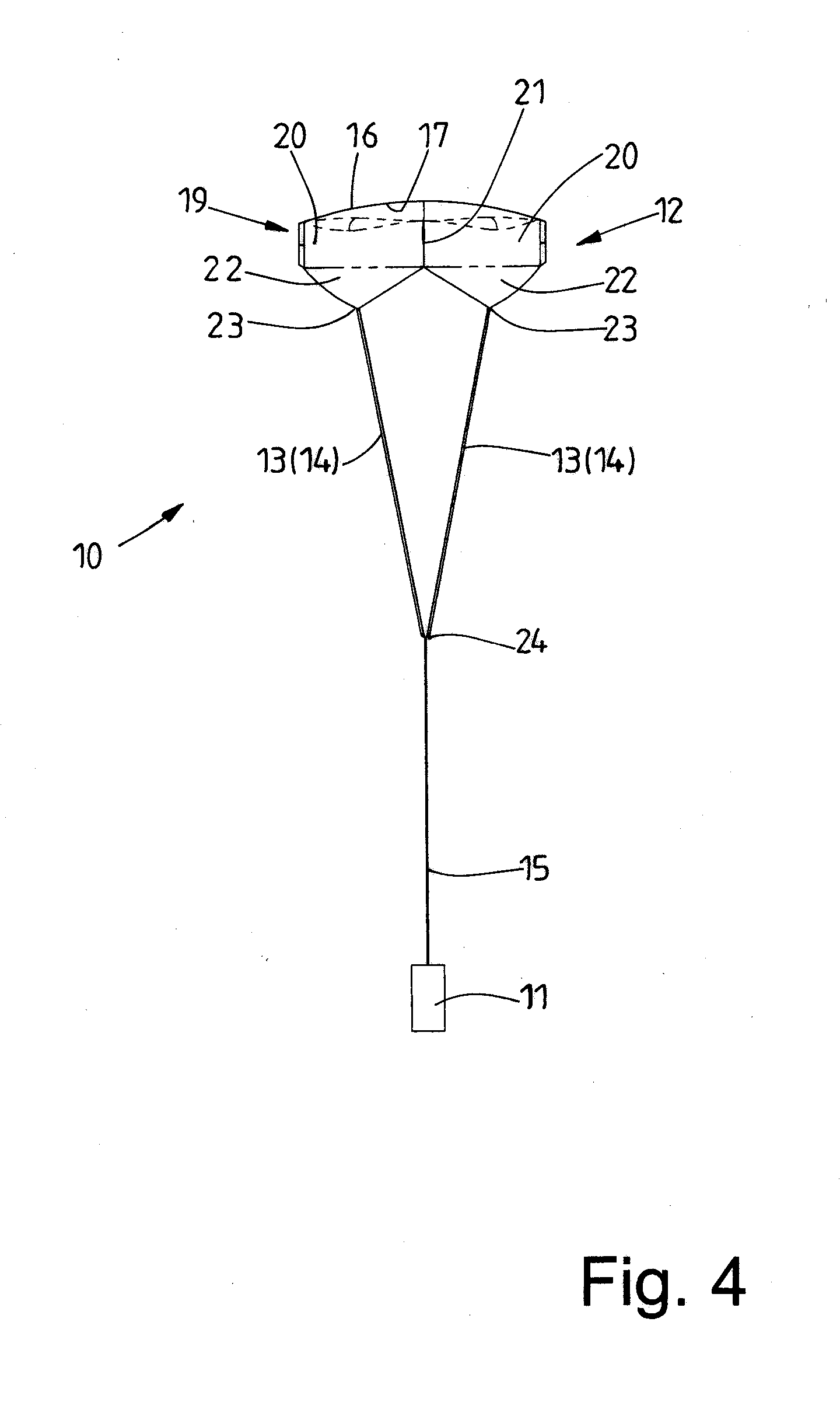
[0039] The parachute canopy 12 exhibits a top surface which is a four-sided top surface 16 in the exemplary embodiment shown. The peripheries 17 of the top surface 16 brought together at four corners 18 in the present exemplary embodiment are of slightly arcuate form, namely outwardly curved (FIG. 6). The top surface 16 is surrounded by a continuous collar 19 which runs roughly perpendicularly to the top surface 16 and extends from the peripheries 17 of the top surface 16. When the parachute 10 is completely deployed or else opened (FIGS. 1, 4 and 5), the collar 19 points downwards starting from the top surface 16 to form the downwardly open parachute canopy 12. In this way, a downwardly open space is created in the parachute canopy 12, in which air gathers when the parachute 10 with the signalling means 11 glides to earth in a decelerated manner. In the four-sided top surface 16 shown here, the collar 19 has four uniformly configured collar portions 20 which are linked together at seam edges 21 or fold edges extending downwards perpendicularly from the corners 18 of the top surface 16.
[0040] In the case of the parachute canopy 12 of the exemplary embodiment of the parachute 10 shown in FIGS. 1 to 6, the free, lower ends of each identical collar portion 20 are provided with a triangular tail 22 which at its lowest point, lying midway between two adjacent edges, in the exemplary embodiment shown, the seam edges 21, has a tip 23. The tips 23 of all four collar portions 20 lie on the same plane. When the parachute 10 is completely opened and deployed, this plane lies with parallel spacing below the plane through which all four corners 18 of the top surface 16 run (FIGS. 4 and 5) and ideally intersects at right angles with the dropping direction of the parachute 10. An upper end of the four suspension lines 13, 14 is fixedly connected to the tip 23 of each of the four collar portions 20. The lower ends of all four suspension lines 13, 14 are brought together at a common connection point 24 and held there. At the connection point 24, an upper end of the tethering line 15 is connected to all four suspension lines 13, 14. The signalling means 11 is fastened to a lower end of the tethering line 15.
[0041] According to the invention, a few suspension lines 14 are elastically extensible or substantially more extensible than the other suspension lines. In the exemplary embodiment shown, only two adjacent suspension lines 14 are configured in a selectively extensible manner, while the two other suspension lines 13 are more or less inextensible. They are only extensible within the framework of what is customary for lines. Where non-extensible suspension lines 13 are referred to in the following, these should be taken to mean suspension lines 13 which are only minimally extensible, namely to an unavoidable extent, but are not extensible to a selective extent according to the invention, as is provided for in the case of the two adjacent suspension lines 14.
[0042] The deliberately extensible suspension lines 14 are formed from one or a plurality of rubber-band-like strands. In particular, the extensible suspension lines 14 comprise rubber bands. The extensible suspension lines 14 are therefore extensible in the elastic range, so that after the elastic suspension lines 14 have been extended, the extension is automatically reversed again. The extensibility or elasticity of the extensible suspension lines 14 may be such that the extensible suspension lines 14 are extensible to twice their starting length in the unloaded state and/or twice the length of the inextensible suspension lines 13 in the elastic, in other words reversible, range. Each extensible suspension line 14 is preferably extensible by at least 30% of its unextended, in other words contracted, starting length. In the exemplary embodiment shown, the extensible suspension lines 14 can be extended until their starting length can extend by the dimension of the diagonal spacing of two opposite corners 18 of the top surface 16 of the parachute canopy 12, but at least the space between opposite seam edges 21 of a collar portion 20. In the exemplary embodiment shown, the elastic suspension lines 14 may extend elastically in a manner similar to a rubber band to 1.5 to 2.5 times their starting length.
[0043] The virtually non-extensible suspension lines 13 are produced from customary line material which is not or virtually not extensible. These may be woven or braided lines or ropes. These lines or ropes may, if necessary, be completely or partially formed from high-tensile fibres, such as glass fibres or carbon fibres. Suspension lines 13 produced from this are very light because as a result of their high-tensile fibres they only have to display a comparatively small diameter.
[0044] The lengths of the non-extensible suspension lines 13 and also the extensible suspension lines 14 are of such dimensions that when the parachute 10 is completely opened or deployed and the parachute canopy 12 is then completely configured and once a constant dropping speed of the parachute with the signalling means 11 suspended therefrom has been reached, the extensible suspension lines 14 have constantly been shortened again, to the extent that all four suspension lines 13, 14, including the extensible suspension lines 14, are roughly the same length, so that the connection point 24 of all four suspension lines 13, 14 lies roughly centrally beneath the middle of the top surface 16 of the parachute canopy 12, when the parachute 10 with the signalling means 11 suspended therefrom floats slowly back earthwards to the ground (FIGS. 1, 4 and 5).
[0045] The single tethering line of the signalling means 11 may be formed from a substantially non-extensible rope or line. It is also conceivable, however, for the tethering line 15 to be elastically extensible in the same way as the suspension lines 14, wherein the elasticity of the tethering line 15 may be greater or smaller than that of the suspension lines 14.
[0046] Using the extensible suspension lines 14, the opening of the parachute 10 after it has been fired upwards and ejected with the signalling means 11 from the rocket casing takes place as follows:
[0047] Because the parachute 10 has still not unfolded and is preferably folded up following its ejection from the rocket casing, said parachute falls with the signalling means 11 virtually unbraked to begin with towards the ground. The parachute canopy 12 of the parachute 10 then gradually starts to deploy. As a result of this, the suspension lines 13 and 14 are subject to tensile load. In the case of the extensible suspension lines 14, this tensile load causes them to extend elastically due to their extensibility, as a result of which the initially effective parachute surface area is reduced.
[0048] The lengthening of the elastic suspension lines 14 can go so far that they are extended in respect of their unloaded starting length to up to twice the length. The extensible suspension lines 11 preferably extend as a consequence of the braking force of the as yet incompletely unfolded parachute canopy 12 so far that the top surface 16 of the parachute canopy 12 extends roughly in a plane longitudinally or slightly obliquely to the dropping direction of the signalling means 11 (FIGS. 2 and 3). In this case, the parachute canopy 12 is roughly stretched between the longer extended suspension lines 14 and the shorter inextensible suspension lines 13. In this way, the configuration of the parachute canopy 12 is changed such that its effective surface area is smaller to begin with, so that the parachute canopy 12 flaps more or less like a flag in the wind. This leads to an initially only slight reduction in the dropping speed of the parachute 10 with the signalling means 10 suspended therefrom. The tensile load of the suspension lines 13 and 14 then falls little by little, as a result of which the suspension lines 14 extended in the elastic region gradually contract and shorten again. In this way, the top surface 16 of the parachute canopy 12 is increasingly pivoted and moved into a roughly horizontal alignment, as a result of which there is a time lag in the unfolding of the parachute canopy 12 and therefore a slower opening or else deployment of the parachute 10, as a result of which due to the downwardly open parachute canopy 12 an air cushion increasingly forms therein which further reduces the dropping speed of the parachute 10 with the signalling means 11. Further elastic shortening of the extensible suspension lines 14 takes place in this case.
[0049] As soon as the parachute 10 and the signalling means 11 suspended therefrom have reached a constant dropping speed, the extension of the elastic suspension lines 14 is cancelled for the most part, namely to the extent that all suspension lines, namely the inextensible suspension lines 13 and the extensible suspension lines 14, are roughly the same length and the connection point 24 of the ends of all suspension lines 13 and 14 and also the signalling means 11 ideally suspend centrally beneath the parachute canopy 12, in other words a lengthening of the tethering line 15 in the direction of the parachute canopy 12 runs roughly centrally through the top surface 16 of the parachute canopy 12. To this end, it is preferably provided that the elasticity or extension behaviour of the elastically extensible suspension lines 14 is adapted to the weight of the parachute 10 and, above all, of the signalling means 11 suspended therefrom. At least with this ideal orientation of the completely opened and folded parachute 10 with the signalling means 11 suspended therefrom, all four suspension lines 13 and 14, even the more extensible, elastic suspension lines 14, are roughly the same length.
[0050] The exemplary embodiments in FIGS. 7 to 14 relate to parachutes each having a parachute canopy made of a planar, flat cut piece. This cut piece is preferably made of a suitably limp material, for example a thin film or a thin fabric. In the exemplary embodiments in FIGS. 7 to 14, the parachute canopy is formed from a simple rectangular, preferably square, cut piece with four corners. The cut piece may be a single piece, so without seams, but it may also be made from a plurality of pieces sewn together.
[0051] The parachutes in the exemplary embodiments according to FIGS. 7 to 14 essentially differ only through the number and arrangement of the parachute lines configured as suspension lines. In particular, the exemplary embodiments differ in the number and arrangement of the extensible suspension lines and more or less inextensible suspension lines. In relation to properties, the extensible suspension lines are comparable with, particularly equitable with, the suspension lines 14 of the previously described exemplary embodiment. In exactly this way, the inextensible suspension lines correspond to the suspension lines 13 of the preceding exemplary embodiment.
[0052] In the exemplary embodiment in FIGS. 7 and 8, three corners of the four-sided cut piece of the parachute canopy 26 are assigned non-extensible suspension lines 28. Only a fourth corner 27 of the parachute canopy 26 is assigned an extensible suspension line 29. Consequently, the parachute 25 has a total of four suspension lines 28, 29 which are brought together at the lower end to a connection point 30 and connected there. This connection point 30 corresponds to the connection point 24 of the parachute 10. At the connection point 30, the signalling means 11 not shown in FIGS. 7 and 8 and also the following FIGS. 9 to 14 can either be arranged directly. However, it is also conceivable for a further parachute line to be fastened to the connection point 30, in particular a tethering line likewise not shown in FIGS. 7 to 14 in the manner of the tethering line 15 in FIGS. 1 to 6, the lower end of said tethering line supporting the signalling means.
[0053] As a consequence of there being only one extensible suspension line 29 on the parachute 25 in FIGS. 7 and 8, during deployment of the parachute canopy 26 only one corner 27 of the parachute canopy 26 is initially folded up, while the other three corners 27 remain at roughly the same height, due to the non-extensible suspension lines 28. In this way, only part of the parachute canopy 26 of the parachute 25 adopts a position during the initial deployment and during the extension of the one extensible suspension line 29 which initially reduces a delay in the parachute 25. When the single extensible suspension line 29 contracts again slightly with a decreasing reduction in the dropping speed of the parachute 25, the parachute canopy 26 adopts its intended symmetrical position, in which the parachute 25 is completely deployed and all four corners 27 of the parachute canopy 26 are located at roughly the same level through a virtually complete reversal of the initial extension of the extensible suspension line 29 and as a result the parachute 25 reduces the dropping speed of the signalling means 11 to the maximum extent possible and thereby decelerates the signalling means to the maximum extent.
[0054] The parachute 25 in the exemplary embodiment in FIGS. 9 and 10 differs from that in FIGS. 7 and 8 only in that of the total of four suspension lines 28, 29 two adjacent suspension lines 29 are extensible. Otherwise, the parachute 25 corresponds to the one in FIGS. 7 and 8. The same reference numbers are therefore used for the same parts in the exemplary embodiment in FIGS. 9 and 10 as in the exemplary embodiment in FIGS. 7 and 8.
[0055] Because in the parachute 25 in FIGS. 9 and 10, two adjacent suspension lines 29 are extensibly configured, with the initial deceleration of the signalling means 10, the entire parachute canopy 26 is positioned obliquely to the vertical dropping direction. This means that the parachute canopy 26 does not yet deploy the full braking effect to begin with, so that the dropping speed of the signalling means is gradually reduced and the extension of the two elastically extensible suspension lines 29 is reversed little by little until all suspension lines 28 and 29 are roughly the same length and the parachute canopy 26 is fully deployed, in that it is oriented transversely to the dropping direction of the signalling means and the dropping speed of the signalling means is thereby reduced to the maximum extent possible.
[0056] The parachute 31 in FIGS. 11 and 12 has a parachute canopy 32 which corresponds to the parachute canopy 26 of the parachute 25. Consequently, the parachute canopy 32 is also formed from a four-sided, preferably square, cut piece with four corners 33.
[0057] The parachute 31 has five parachute lines which are configured as four extensible suspension lines 34 and a non-extensible suspension line 35. The four extensible suspension lines 34 are the same length. Moreover, the non-extensible suspension line 35 is exactly the same length as the four extensible suspension lines 35 in the non-extended state. The four extensible suspension lines 34 are fastened to the four corners 33 of the four-sided, particularly square, parachute canopy 32. Conversely, the non-extensible suspension line 35 is fastened with an upper end in the center of the four-sided parachute canopy 32. The lower end of the non-extensible suspension line 35 is connected to the connection point 30 in exactly the same way as the extensible suspension lines 34 which lead to the corners 33 of the parachute canopy 32. It is, however, conceivable in the exemplary embodiment shown that the central, non-extensible suspension line 35 is slightly longer than the extensible suspension lines 34 in their unextended state. When the parachute 31 is fully deployed, in other words when the outer suspension lines 34 are unextended, the longer central suspension line 35 gives the parachute canopy 32 on the underside, in other words more or less the windward side when the parachute 31 is dropping, a concave shape.
[0058] During the initial deceleration, the four outer suspension lines 34 are elastically extended, as a result of which the corners 33 of the parachute canopy 32 fold up, while the parachute canopy 32 is held down in the center by the non-extensible suspension line 35. In this way, when the suspension lines 34 are still extended, the parachute canopy 32 adopts an initially convex shape in relation to the windward side of the dropping parachute 31, in which the underside of the parachute canopy 32 is curved downwards. In this way, the dropping speed of the signalling means suspended from the parachute 31 is initially reduced by only a relatively small amount. During the subsequent gradual reversal of the elastic extension of the extensible suspension lines 34, the corners 33 of the parachute canopy 32 are pulled downwards and the parachute canopy 32 is thereby practically inverted again, as a result of which the parachute canopy 32 adopts a concave form on its lower side once again and the braking potential of the parachute 31 is thereby increased. The parachute 31 which is thereby completely deployed then decelerates the signalling means to the maximum extent possible, as a result of which the parachute 31 reduces the dropping speed of the signalling means 11 in respect of the depiction in FIGS. 11 and 12 with the suspension lines 34 extended.
[0059] FIGS. 13 and 14 show a further exemplary embodiment of a parachute 37 which substantially corresponds to the parachute 31 in FIGS. 11 and 12. The parachute 31 also has a square parachute canopy 32 made of a preferably planar cut piece, wherein extensible suspension lines 34 are fastened to the four corners 33 of the parachute canopy 32.
[0060] Unlike with the previously described parachute 31 (FIGS. 11 and 12), with the parachute in FIGS. 13 and 14, four non-extensible suspension lines 35 are provided. These four non-extensible suspension lines 35 are all spaced apart from the four corners 33 of the parachute canopy 32 towards the center thereof. The fastening points of the non-extensible, inner suspension lines 35 on the parachute canopy 32 may lie on imaginary connection lines between two diagonally opposite corners 33 of the parachute canopy 32 in each case, but also on center lines of the four-sided cut piece of the parachute canopy. Through this arrangement, during the initial unfolding of the parachute 31, a central, four-sided part of the parachute canopy 32 is held by the equally long, non-extensible inner suspension lines 35 in a roughly planar orientation transversely to the perpendicular dropping direction. The four equally long outer extensible suspension lines 34 are elastically extended during the initial deployment of the parachute 31, so that an outer annular region of the parachute canopy 32 between the fastening points of the inextensible suspension lines 35 on the parachute canopy 32 and the outer corners 33 of the same is folded up or inverted upwards, as a result of which the underside of the parachute canopy 32 takes on a convex form during initial deployment.
[0061] Through the partially deployed or effective parachute 31 shown in FIGS. 13 and 14, the dropping speed of the signalling means fastened to the connection point 36 directly or via a tethering line is successively reduced, in that the extension of the elastically extensible suspension lines 34 is reduced little by little. Once the extension of the elastic suspension lines 34 is cancelled, the suspension lines 34 are either just as long as the non-extensible suspension lines 35 or slightly shorter, as a result of which the parachute canopy 32 takes on a flat or else concave form on the windward underside of the parachute canopy 32 with a completely effective and fully deployed parachute 31. The parachute canopy 32 is then practically conversely shaped, as in the depiction in FIGS. 13 and 14 showing the partially effective parachute 31. With this embodiment of the parachute canopy 32 which is concave and inverted downwards on the underside, the parachute 31 produces its maximum braking effect, which allows the signalling means suspended from the parachute 31 to drop to the ground at the slowest possible dropping speed.
[0062] In the manner described above, parachutes are also configured for parachute illumination rockets, parachute rockets with observational means such as cameras, probes or sensors, for example, and also parachute signalling projectiles, parachute flares and parachute projectiles for observational means fired on a ballistics trajectory, in that parachutes of this kind also exhibit at least one elastically extensible suspension line and at least one non-extensible or not substantially extensible suspension line. The opening jerk of the parachute is thereby reduced in exactly the same way as has been described above in connection with parachute signalling rockets and parachute signalling munitions.
LIST OF REFERENCE NUMBERS
[0063] 10 Parachute [0064] 11 Signalling means [0065] 12 Parachute canopy [0066] 13 Suspension line [0067] 14 Suspension line (extensible) [0068] 15 Tethering line [0069] 16 Top surface [0070] 17 Periphery [0071] 18 Corner [0072] 19 Collar [0073] 20 Collar portion [0074] 21 Seam edge [0075] 22 Tail [0076] 23 Tip [0077] 24 Connection point [0078] 25 Parachute [0079] 26 Parachute canopy [0080] 27 Corner [0081] 28 Suspension line [0082] 29 Suspension line (extensible) [0083] 30 Connection point [0084] 31 Parachute [0085] 32 Parachute canopy [0086] 33 Corner [0087] 34 Suspension line (extensible) [0088] 35 Suspension line [0089] 36 Connection point
* * * * *
D00000
D00001
D00002
D00003
D00004
D00005
D00006
D00007
D00008
XML
uspto.report is an independent third-party trademark research tool that is not affiliated, endorsed, or sponsored by the United States Patent and Trademark Office (USPTO) or any other governmental organization. The information provided by uspto.report is based on publicly available data at the time of writing and is intended for informational purposes only.
While we strive to provide accurate and up-to-date information, we do not guarantee the accuracy, completeness, reliability, or suitability of the information displayed on this site. The use of this site is at your own risk. Any reliance you place on such information is therefore strictly at your own risk.
All official trademark data, including owner information, should be verified by visiting the official USPTO website at www.uspto.gov. This site is not intended to replace professional legal advice and should not be used as a substitute for consulting with a legal professional who is knowledgeable about trademark law.