Forend-mounted Heatshield Arrangement For Firearms
Chvala; John R.
U.S. patent application number 14/314592 was filed with the patent office on 2015-12-31 for forend-mounted heatshield arrangement for firearms. This patent application is currently assigned to ATI IP, LLC. The applicant listed for this patent is ATI IP, LLC. Invention is credited to John R. Chvala.
| Application Number | 20150377584 14/314592 |
| Document ID | / |
| Family ID | 54930119 |
| Filed Date | 2015-12-31 |

| United States Patent Application | 20150377584 |
| Kind Code | A1 |
| Chvala; John R. | December 31, 2015 |
FOREND-MOUNTED HEATSHIELD ARRANGEMENT FOR FIREARMS
Abstract
A mounting arrangement for a firearm having a receiver, a barrel and a magazine tube includes an elongated heatshield body having a set of mounting feet provided thereon. A forend assembly includes a U-shaped forend body and a U-shaped bracket arrangement received and retained within the forend body for receiving the magazine tube and connecting the mounting feet to the forend assembly such that an entire length of the heatshield body is mounted in a continuous spaced floating relationship over the barrel to prevent any contact between the heatshield body and the barrel.
| Inventors: | Chvala; John R.; (Grafton, WI) | ||||||||||
| Applicant: |
|
||||||||||
|---|---|---|---|---|---|---|---|---|---|---|---|
| Assignee: | ATI IP, LLC Cedarburg WI |
||||||||||
| Family ID: | 54930119 | ||||||||||
| Appl. No.: | 14/314592 | ||||||||||
| Filed: | June 25, 2014 |
| Current U.S. Class: | 42/75.01 |
| Current CPC Class: | F41C 23/16 20130101 |
| International Class: | F41C 23/16 20060101 F41C023/16 |
Claims
1. A heatshield mounting arrangement adapted to be used on a &emit having a receiver, a barrel extending forwardly of the receiver and a mounting tube extending forwardly from the receiver beneath the barrel, the mounting arrangement comprising: a heatshield body having a retaining structure provided thereon, the heatshield body being adapted to overlie the barrel of a firearm; and a forend assembly including a forend body adapted to receive the magazine tube and a bracket arrangement constructed to connect the retaining structure of the heatshield body to the forend body and adapted to mount the heatshield body along an entire length thereof in a continuous spaced apart relationship over the barrel.
2. The heatshield mounting arrangement of claim 1, wherein the bracket arrangement is received and retained within the forend body.
3. The heatshield mounting arrangement of claim 1, wherein the heatshield body extends. upwardly from the forend assembly.
4. The heatshield mounting arrangement of claim 1, wherein the retaining structure of the heatshield body includes a set of mounting feet extending from bottom edges of the heatshield body.
5. The heatshield mounting arrangement of claim 1, wherein the forend body has a U-shaped construction, and a length which is shorter than a length of the heatshield body.
6. The heatshield mounting arrangement of claim 1, wherein upper ends of the forend body are constructed with recesses for receiving the mounting feet of the heatshield body.
7. The heatshield mounting arrangement of claim 6, wherein the bracket arrangement includes a set of spaced apart U-shaped brackets.
8. The heatshield mounting arrangement of claim 7, wherein each of the U-shaped brackets has a bottom wall joined to a lower wall of the forend body and a pair of spaced apart sidewalk extending from the bottom wall.
9. The heatshield mounting arrangement of claim 8, wherein a that set of fasteners is provided to secure the bottom walls of the U-shaped brackets to the lower wall of the forend body.
10. The heatshield mounting arrangement of claim 8, wherein the sidewalk of the U-shaped brackets have upper ends provided with throughholes in communication with the recesses formed in the upper ends of the forend body.
11. The heatshield mounting arrangement of claim 10, wherein a second set of fasteners is provided to secure the upper ends of the U-shaped brackets with the mounting feet of the heatshield body.
12. The heatshield mounting arrangement of claim 7, wherein outer surfaces of the U-shaped brackets are engaged against an inner surface of the forend body.
13. A forend assembly adapted to be used in a heatshield mounting arrangement for mounting a heatshield over a barrel of a firearm, the forend assembly comprising: an elongated U-shaped forend body having a lower wall and a pair of spaced apart sidewalk rising from the lower wall and provided with upper ends adapted to be secured to the heatshield; and a U-shaped bracket arrangement received and retained within the forend body, the U-shaped bracket arrangement having a lower attachment area secured to the lower wall of the forend body, and an upper attachment area aligned with the upper ends of the forend body and adapted to be connected to the heatshield.
14. The forend assembly of claim 13, wherein the upper ends of the forend body extend inwardly of the sidewalls.
15. The forend assembly of claim 13, wherein a first set of fasteners is provided to secure the lower attachment area of the U-shaped bracket arrangement to the lower wall of the forend body.
16. The forend assembly of claim 13, wherein a second set of fasteners is received in the upper attachment area of the U-shaped bracket arrangement and is adapted to secure the heatshield thereto.
17. The forend assembly of claim 13, wherein the U-shaped bracket arrangement is formed by a set of spaced apart U-shaped brackets having outer surfaces which are engaged against an inner surface of the forend body.
18. A mounting arrangement for a firearm having a receiver, a barrel extending forwardly from the receiver and a magazine tube extending forwardly from the receiver beneath the barrel, the mounting arrangement comprising: an elongated heatshield body having a set of mounting feet provided thereon; and a forend assembly including a U-shaped forend body and a U-shaped bracket arrangement received and retained within the forend body for receiving the magazine tube and connecting the mounting feet to the forend assembly such that an entire length of the heatshield body is mounted in a continuous spaced floating relationship over the barrel to prevent any contact between the heatshield body and the barrel.
19. The mounting arrangement of claim 18, wherein a continuous unobstructed space is defined between the barrel and the heatshield body along the entire length thereof.
20. The mounting arrangement of claim 18, including a fastener arrangement for securing the U-shaped bracket arrangement within the forend body, and connecting the mounting feet to upper ends of the forend body.
Description
BACKGROUND OF THE INVENTION
[0001] The present disclosure relates generally to firearm accessories and more particularly, pertains to a heatshield mounting arrangement provided for a barrel of a firearm or weapon.
[0002] It is well known to those skilled in the art that rapid-fire weapons, such as semi-automatic or automatic rifles and shotguns are characterized by the heating of their metal barrels to relatively high temperatures, often in excess of 600 degrees Fahrenheit. At such intense temperatures, the barrels cannot be comfortably or safely handled by the shooter of the weapon. Various expedients, typically in the form of heatshield assemblies, have been resorted to in the past in an attempt to protect the hands of the person firing the weapon from harmful contact with the excessively hot barrel.
[0003] Certain known heatshield assemblies typically include a curved, perforated metallic body having, front and rear tabs, clamps, flanges or other retaining structures which are integrally formed on the body. These integral retaining structures are bent, clamped and secured with additional fasteners to the metal barrel to mount the heatshield assembly along substantially the entire length of the barrel. Such known heatshield assemblies have been designed to allow dissipation of heat to protect the shooter's hands during the rapid discharging of the firearm. Unfortunately, installation and use of these currently available heatshield assemblies results in sliding metal-to-metal contact between the heatshield body and the barrel causing possible damage to the barrel which is undesirable.
[0004] Accordingly, there is a need to provide a heatshield mounting arrangement in which a heatshield body is secured to the firearm in a suspended, floating relationship over the barrel so as to prevent any direct metal-to-metal contact between the heatshield body and the barrel and eliminate any scratching or damage to the barrel. There is an additional need to provide a firearm heatshield having a forend mounting arrangement which prevents movement of the heatshield body relative to the barrel dining use.
SUMMARY OF THE INVENTION
[0005] The present disclosure relates to a heatshield mounting arrangement adapted to be used on a firearm having a receiver, a barrel extending forwardly of the receiver and a magazine rube extending forwardly from the receiver beneath the barrel. The mounting arrangement includes a heatshield body having a retaining structure provided thereon, the heatshield body being adapted to overlie the barrel of a firearm. A forend assembly includes a forend body adapted to receive the magazine tube, and a bracket arrangement constructed to connect the retaining structure of the heatshield body to the forend body and adapted to mount the heatshield body along an entire length thereof in a continuous spaced apart relationship over the barrel.
[0006] In the heatshield mounting arrangement., the bracket arrangement is received and retained within the forend body, and the heatshield body extends upwardly from the forend assembly. The retaining structure of the heatshield body includes a set of mounting feet extending from bottom edges of the heatshield body. The forend body has a U-shaped construction, and a length which is shorter than a length of the heatshield body. Upper ends of the forend body are constructed with recesses for receiving the mounting feet of the heatshield body. The bracket arrangement includes a set of spaced apart U-shaped brackets. Each of the U-shaped brackets has a bottom wall joined to a lower wall of the forend body, and a pair of spaced apart sidewalls extending from the bottom wall. A first set of fasteners is provided to secure the bottom walls of the U-shaped brackets to the lower wall of the forend body. The sidewalls of the U-shaped brackets have upper ends provided with throughholes in communication with the recesses formed in the upper ends of the forend body. A second set of fasteners is provided to secure the upper ends of the U-shaped brackets with the mounting feet of the heatshield body. Outer surfaces of the U-shaped brackets are engaged against an inner surface of the forend body.
[0007] The present disclosure also relates to a forend assembly adapted to be used in a heatshield mounting arrangement for mounting a heatshield over a barrel of a firearm. The forend assembly includes an elongated U-shaped forend body having a lower wall and a pair of spaced apart sidewalls rising from the lower wall, and provided with upper ends adapted to be secured to the heatshield. A U-shaped bracket arrangement is received and retained within the forend body. The U-shaped bracket arrangement has a lower attachment area secured to the lower wall of the forend body, and an upper attachment area aligned with the upper ends of the forend body and adapted to be connected to the heatshield.
[0008] Upper ends of the forend body extend inwardly of the sidewalls. A first set of fasteners is provided to secure the lower attachment area of the U-shaped bracket arrangement to the lower wall of the forend body. A second set of fasteners is received in the upper attachment area of the U-shaped bracket arrangement and is adapted to secure the heatshield thereto. The U-shaped bracket arrangement is formed by a set of spaced apart U-shaped brackets having outer surfaces which are engaged against an inner surface of the forend body.
[0009] The present disclosure further relates to a mounting arrangement for a firearm having a receiver, a barrel extending forwardly from the receiver and a magazine tube extending forwardly from the receiver beneath the barrel. The mounting arrangement includes an elongated heatshield body having a set of mounting feet provided thereon. A forend assembly includes a U-shaped forend body and a U-shaped bracket assembly received and retained within the forend body for receiving the magazine tube and connecting the mounting feet to the forend assembly such that an entire length of the heatshield body is mounted in a continuous spaced floating relationship over the barrel to prevent any contact between the heatshield body and the barrel.
[0010] A continuous unobstructed space is defined between the barrel and the heatshield body along the entire length thereof. A fastener arrangement is provided for securing the U-shaped bracket arrangement within the forend body, and connecting the mounting feet to upper ends of the forend body.
BRIEF DESCRIPTION OF THE DRAWINGS
[0011] The drawings illustrate the best mode presently contemplated in carrying out the disclosure. In the drawings:
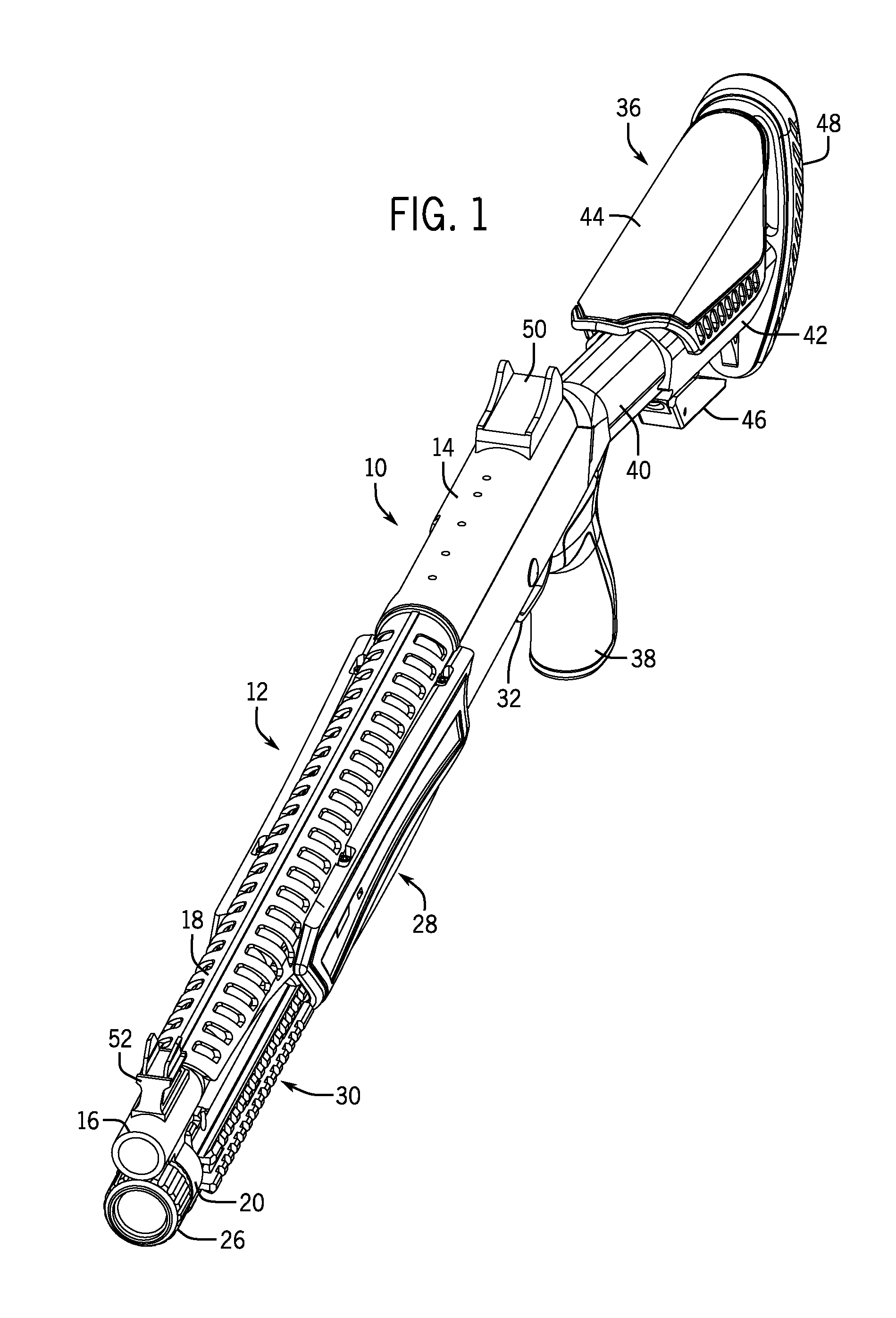
[0012] FIG. 1 is a top perspective view of a shotgun provided with a forend-mounted heatshield in accordance with the present disclosure;
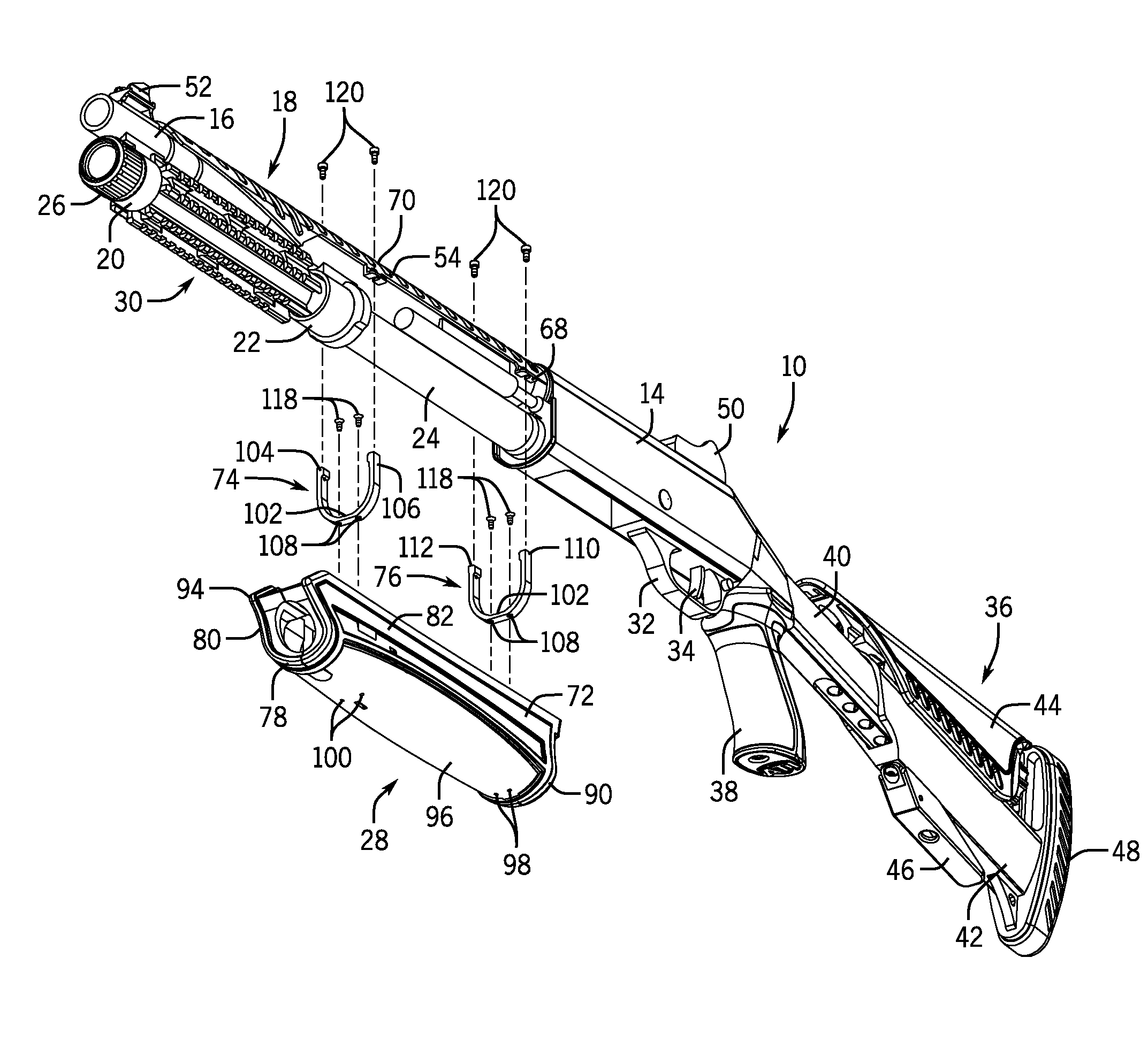
[0013] FIG. 2 is an exploded top perspective view of the shotgun and the heatshield of FIG. 1;
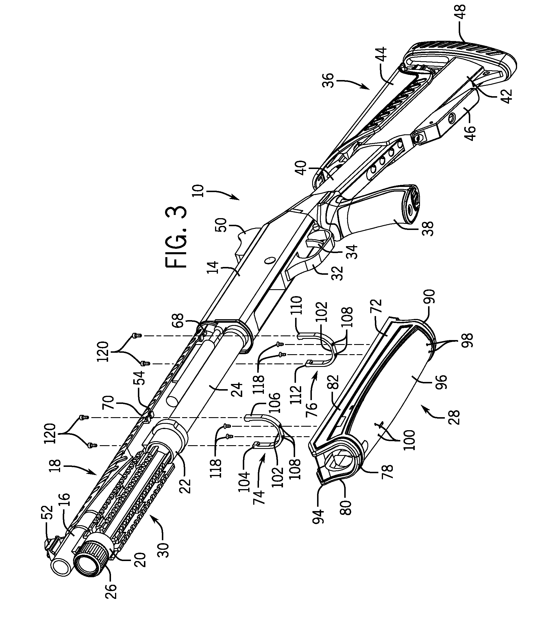
[0014] FIG. 3 is an exploded bottom perspective view of the shotgun and a forend assembly to which the heatshield is mounted;
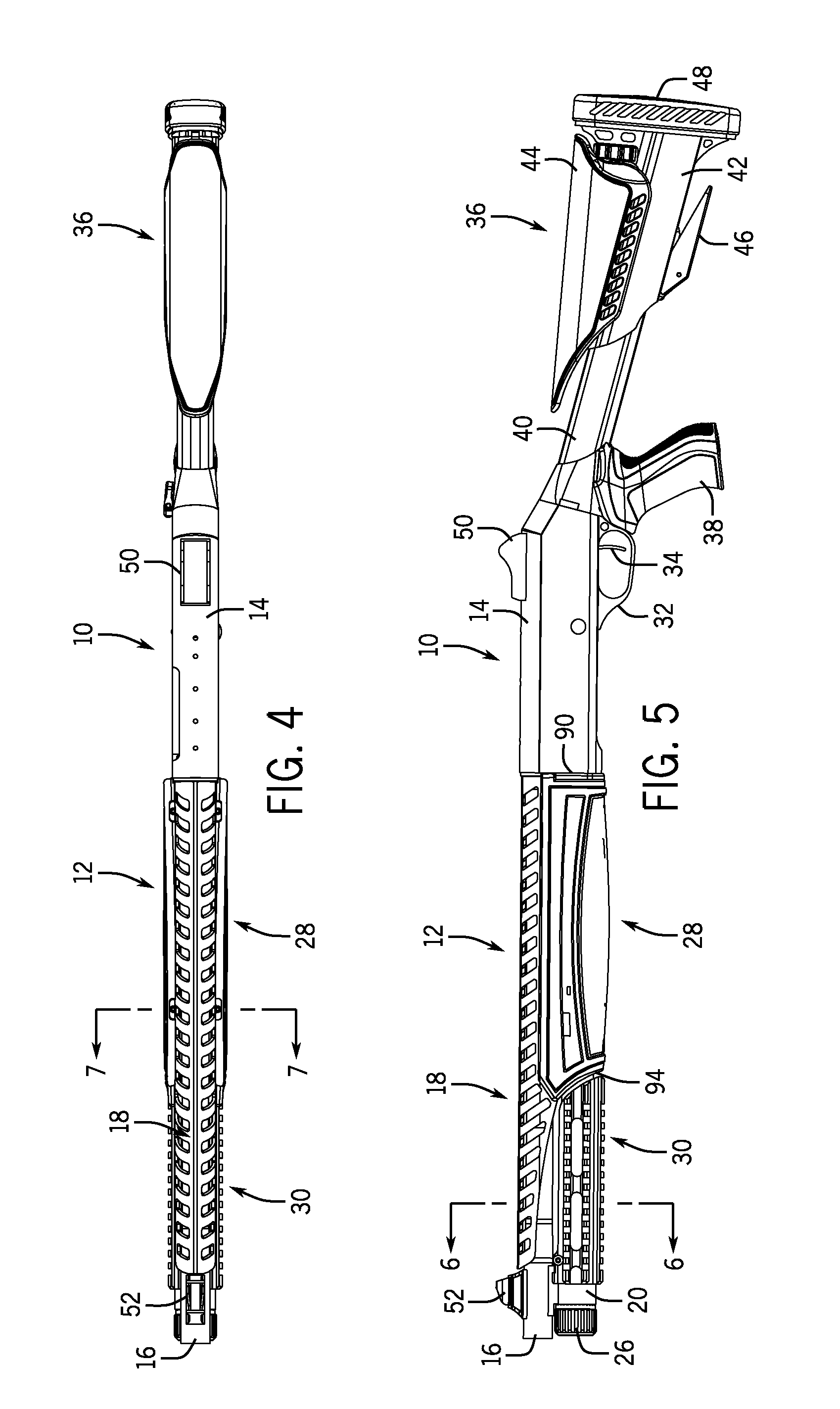
[0015] FIG. 4 is a top view of the shotgun of FIG. 1;
[0016] FIG. 5 is an elevational view of the shotgun of FIG. 1;
[0017] FIG. 6 is an enlarged sectional view taken on line 6-6 of FIG. 5; and
[0018] FIG. 7 is an enlarged sectional view taken on line 7-7 of FIG. 4.
DETAILED DESCRIPTION OF THE INVENTION
[0019] Referring to the drawings, FIGS. 1-7 illustrate a firearm, such as a shotgun 10, incorporating a heatshield mounting arrangement 12 of the present disclosure.
[0020] As illustrated in FIGS. 1-5, the shotgun 10 typically includes a receiver 14 for receiving and ejecting shotgun cartridges, and a barrel 16 extending forwardly from the receiver 14 for guiding and delivering the loads of the shotgun cartridges once the shotgun 10 is fired. A heatshield 18 is sized and shaped to be suspended over an upper portion of the barrel 16 as will be more fully described herein. The barrel 16 has a metal construction, and is integrally formed with a depending barrel lug 20 and a depending barrel collar 22 (FIG. 3). A cartridge-storing magazine tube 24 extends forwardly from the receiver 14 beneath the barrel 16, and passes through the barrel lug 20 and the barrel collar 22. A forward threaded end of the magazine tube 24 extends beyond the barrel lug 20, and is held thereto by a magazine cap 26. A gripping open top forend assembly 28 is provided at rear portions of the barrel 16 and the magazine tube 24, and a mounting rail device 30 is positioned around a forward portion of the magazine tube 24 between the barrel lug 20 and the forend assembly 28. The mounting rail device 30 allows a variety of different accessories to be mounted at different angular positions around the magazine tube 24.
[0021] In addition, shotgun 10 also includes a trigger guard 32 and a trigger 34. which depend from the receiver 14, and a pistol grip stock assembly 36 which extends rearwardly of the receiver 14. The stock assembly 36 is configured with a pistol grip 38, a buffer tube 40, a stock 42, a cheekrest 44, a lever arrangement 46 and a buttpad assembly 48. A rear sight 50 is secured to an upper portion of the receiver 14, and a front sight 52 is joined to an upper front end of the barrel 16.
[0022] Referring now to FIGS. 2, 6 and 7, the heatshield 18 has a heatshield body 54 which is constructed of an elongated, perforated and inverted shell which is preferably comprised of anodized aluminum or another suitable metal material. The heatshield body 54 is configured with a front end 56 and a rear end 58, and is integrally formed with an arcuate upper wall 60 and a pair of opposed sidewalls 62, 64 depending from the upper wall 60. The sidewalls 62, 64 are formed along the length of the heatshield body 54 with a series of spaced vent openings 66 which extend laterally outwardly and downwardly from the upper wall 60 to permit airflow through the heatshield 18. Bottom edges of the sidewalls 62, 64 are provided with a retaining structure embodied in a first pair of outwardly projecting mounting feet 68 located adjacent the rear end 58, and a second pair of outwardly projecting mounting feet 70 located in the central portion of the heatshield body 54.
[0023] As best seen in FIGS. 3 and 7, forend assembly 28 includes an elongated U-shaped forend body 72, and a bracket arrangement formed by a pair of spaced apart U-shaped brackets 74, 76 designed to be received and retained within the forend body 72. The thread body 72 is typically constructed of a polymer material, and has a length which is shorter than a length of the heatshield body 54. The forend body 72 is integrally formed with an arcuate lower wall 78 and a pair of spaced apart sidewalls 80, 82 having respective spaced upper ends 84. 86 which extend inwardly of the sidewalls 80, 82 and define an open top. As best seen in FIG. 2, the upper ends 84, 86 are formed with a first pair of recesses 88 located near a rear end 90 of the forend body 72, and a second pair of recesses 92 spaced towards a front end 94. The recesses 88, 92 are configured to receive the mounting feet 68, 70 on the heatshield body 54, and to be supported on lower apertured walls 87 of the recesses 88, 92. A portion of the lower wall 78 is preferably provided with a non-slip textured coating 96 for improving the gripping ability of the forend body 72. The lower wall 78 and coating 96 are formed therethrough with a first pair of apertures 98 adjacent the rear end 90 of forend body 72, and a second pair of apertures 100 spaced forwardly near a front end 94 of the forend body 72.
[0024] Each of the U-shaped brackets 74, 76 has an identical construction, and includes a bottom wall 102 joining a pair of opposed sidewalls 104, 106. Outer surfaces of the brackets 74, 76 are sized and shaped to engage the inner surface of the forend body 72. Each bottom wall 102 is formed with a pair of spaced apart holes 108 which are designed to be aligned with the apertures 98, 100 provided in the forend body 72. Each of the sidewalls 104, 106 has upper ends 110, 112 formed with respective throughholes 114, 116 (FIG. 6) which are alignable with suitable apertures provided in the mounting feet 68, 70 on the heatshield body 54 as well as with the recesses 88, 92 of the forend body 72.
[0025] A first set of threaded fasteners 118 is designed to be passed through the holes 108 in the bottom walls 102 of the U-shaped brackets 74, 76 and to be screwthreaded into the apertures 98, 100 formed through the lower wall 78 and coating 96 of the forend body 72. A second set of threaded fasteners 120 is designed to be passed through apertures in the mounting feet 68, 70 on the heatshield body 54 when the mounting feet 68, 70 are received in the recesses 88, 92 of the forend body 72, and to be screwthreaded into the throughholes 114. 116 of the brackets 74, 76 once the brackets 74, 76 are secured to the lower wall 78 of the forend body 72.
[0026] When it is desired to mount the heatshield body 54 on the shotgun 10, the U-shaped brackets 74, 76 are slidably received within the forend body 72 such that the bracket holes 108 are aligned with the forend body apertures 98, 100. The brackets 74, 76 are retained within the forend body 72 by turning the fasteners 118 into the apertures 98, 100 formed through the lower wall 78. The forend assembly 28 is then moved upwardly and positioned around the barrel collar 22 and the rear portion of the magazine tube 24, and the heatshield body 54 is positioned over the rear portion of the barrel 16 so that the mounting feet 68, 70 are received in the recesses 88, 92 at the upper end of the forend body 72. Thereafter, the fasteners 120 are passed through apertures in the mounting feet 68, 70 and threaded into the throughholes 114, 116 at the upper ends 110, 112 of the brackets 74, 76 secured to the lower wall 78 of the forend body 72.
[0027] With this assembly, the lower portion of the magazine tube 24 is engaged by the bottom walls 102 of the U-shaped brackets 74, 76. The sidewalls 104, 106 of the brackets 74, 76 extend upwardly spaced from the magazine tube 24, and are engaged with the inner surface of the sidewalls 80, 82 of the forend body 72. Upper ends 84, 86 of the forend body 72 lie adjacent lower portions of the barrel 16. The forend body 72 is designed to cover or shield the rear portion of the magazine tube 24, and to shield a lower rear portion of the barrel 16 as seen in FIG. 2. The entire length of the heatshield body 54 is held continuously spaced from and suspended in floating relationship over the barrel 16. The heatshield body 54 is secured to the top of the forend body 72 so as to prevent any movement of the heatshield body 54 relative to the barrel 16 during use of the shotgun 10. As seen in FIG. 5, the rear end 90 of the forend body 72 lies adjacent a front edge of the receiver 14, and the front end 94 of the forend body 72 lies adjacent a rear end of the mounting rail device 30.
[0028] In accordance with the present disclosure, the heatshield mounting arrangement 12 is defined by the heatshield body 54 having a retaining structure 68, 70 and the forend assembly 28 including the forend body 72 and the bracket arrangement 74, 76 which connects the retaining structure 68, 70 of the heatshield body 54 to the top end of the forend body 72. The heatshield mounting arrangement functions to mount the heatshield body 54 along an entire length thereof in a continuous spaced apart, floating relationship over the barrel 16. That is, the mounting arrangement 12 creates a continuous unobstructed space 122 between the outer surface of the barrel 16 and the inner surface of the heatshield body 54 over the entire length of the heatshield body 54 so that contact between the barrel 16 and the heatshield 18 is prevented. Such a design ensures that the metal barrel 16 will not be scratched or damaged, and that there is no direct transfer of heat from the barrel 16 to the heatshield 18 so that heat is dissipated and cooler ambient air is communicated through the vent openings 66 of the floating heatshield 18.
[0029] Various alternatives are contemplated as being within the scope of the following claims particularly pointing out and distinctly claiming the subject matter regarded as the invention.
* * * * *
D00000
D00001
D00002
D00003
D00004
D00005
XML
uspto.report is an independent third-party trademark research tool that is not affiliated, endorsed, or sponsored by the United States Patent and Trademark Office (USPTO) or any other governmental organization. The information provided by uspto.report is based on publicly available data at the time of writing and is intended for informational purposes only.
While we strive to provide accurate and up-to-date information, we do not guarantee the accuracy, completeness, reliability, or suitability of the information displayed on this site. The use of this site is at your own risk. Any reliance you place on such information is therefore strictly at your own risk.
All official trademark data, including owner information, should be verified by visiting the official USPTO website at www.uspto.gov. This site is not intended to replace professional legal advice and should not be used as a substitute for consulting with a legal professional who is knowledgeable about trademark law.