Harmonically De-Tuned Flash Suppressor for Firearms
Pappas; Steven Michael ; et al.
U.S. patent application number 14/120804 was filed with the patent office on 2015-12-31 for harmonically de-tuned flash suppressor for firearms. The applicant listed for this patent is Joshua Dan MacMurray, Steven Michael Pappas. Invention is credited to Joshua Dan MacMurray, Steven Michael Pappas.
| Application Number | 20150377577 14/120804 |
| Document ID | / |
| Family ID | 54930114 |
| Filed Date | 2015-12-31 |


View All Diagrams
| United States Patent Application | 20150377577 |
| Kind Code | A1 |
| Pappas; Steven Michael ; et al. | December 31, 2015 |
Harmonically De-Tuned Flash Suppressor for Firearms
Abstract
A prong-type harmonically de-tuned flash suppressor that is usable with a sound suppressor. As a consequence of its harmonic de-tuning, the flash suppressor does not produce an audible ping when the firearm to which it is attached is discharged, due to harmonic variance among the prongs of the flash suppressor. Harmonic variance, or de-tuning, of the flash suppressor is accomplished by varying centers of gravity of the prongs such that each prong of the flash suppressor has a different fundamental harmonic than each other prong. This harmonic de-tuning of the flash suppressor is accomplished while maintaining each prong at an equal length to each other prong, and while maintaining the general exterior appearance of each prong as being about the same as the general exterior appearance of each other prong. Centers of gravities of the prongs, and thus fundamental harmonics of the prongs, may be varied by placing payloads within the prongs which serve as harmonic dampers. The payloads may be fixed within the prongs, or they may be allowed to freely move within the prongs.
| Inventors: | Pappas; Steven Michael; (Marion, UT) ; MacMurray; Joshua Dan; (Murray, UT) | ||||||||||
| Applicant: |
|
||||||||||
|---|---|---|---|---|---|---|---|---|---|---|---|
| Family ID: | 54930114 | ||||||||||
| Appl. No.: | 14/120804 | ||||||||||
| Filed: | June 30, 2014 |
| Current U.S. Class: | 89/14.2 |
| Current CPC Class: | F41A 21/34 20130101 |
| International Class: | F41A 21/34 20060101 F41A021/34 |
Claims
1. A harmonically-detuned flash suppressor for a firearm, and which may be capable of use in conjunction with a sound suppressor, the flash suppressor comprising: a body which is attachable to a firearm barrel, a plurality of prongs extending from said body distally from said firearm barrel, said prongs being generally the same length as each other, at least a plurality of said prongs having load-carrying cavities therein, at least a plurality of said cavities having a payload located therein, said load-carrying cavities and payloads in combination serving to result in each prong having approximately the same mass as each other prong, said load-carrying cavities and payloads in combination serving to result in each prong having a different center of gravity as each other prong, said different centers of gravity resulting in each prong having a different fundamental harmonic resonance from each other prong, and said differing prong harmonics of yielding a harmonically de-tuned flash hider.
2. A flash suppressor as recited in claim 1 wherein said payloads serve as harmonic dampers.
3. A flash suppressor as recited in claim 2 wherein said harmonic dampers are each in a fixed position within their load-carrying cavities.
4. A flash suppressor as recited in claim 2 wherein said harmonic dampers are free to move within said load-carrying cavities.
5. A flash suppressor as recited in claim 4 further comprising plugs in said load-carrying cavities to prevent said harmonic dampers from escaping from said cavities.
6. A flash suppressor as recited in claim 1 wherein at least one of said payloads includes a matrix material.
7. A flash suppressor as recited in claim 2 wherein each of said harmonic dampers is located within its prong a different distance from the muzzle of said firearm barrel than each of said other harmonic dampers.
8. A harmonically-detuned flash suppressor for a firearm comprising: a body which is attachable to a firearm barrel, a plurality of prongs extending from said body distally from said firearm barrel, a means for attaching a sound suppressor to the flash suppressor, and at least a plurality of said prongs having cavities therein; wherein said prongs each has a different center of mass; and wherein said prongs each has a different fundamental harmonic resonance.
9. A flash suppressor as recited in claim 8 wherein the harmonic resonance of each of said prongs tends to interfere with the harmonic resonance of at least another of said prongs.
10. A flash suppressor as recited in claim 8 further comprising a harmonic damper located in each of said cavities.
11. A flash suppressor as recited in claim 10 wherein each of said prongs with said harmonic dampers installed is of approximately the same mass as each of said other prongs.
12. A flash suppressor as recited in claim 11 wherein said harmonic dampers are placed at different locations within the prongs, resulting in differing centers of mass for said prongs.
13. A flash suppressor as recited in claim 10 wherein each of said harmonic dampers has the same specific gravity of each other harmonic damper.
14. A flash suppressor as recited in claim 10 wherein each of said harmonic dampers has a different specific gravity from each other harmonic damper.
15. A flash suppressor as recited in claim 10 wherein the combination of prong and harmonic damper has the same mass as each other prong and harmonic damper combination.
16. A flash suppressor as recited in claim 10 wherein each of said harmonic dampers has a different mass from other of said harmonic dampers.
17. A harmonically-detuned flash suppressor for a firearm comprising: a body which is attachable to a firearm barrel, a plurality of prongs extending from said body, each of said prongs being of equal mass, each of said prongs being of equal length, at least a plurality of said prongs having a cavity located within it, and each of said cavities having a payload located therein; wherein each of said prongs each has a different center of mass from said other prongs; wherein each of said prongs each has a different harmonic resonance from said other prongs.
18. A flash hider as recited in claim 17 wherein at least one of said payloads is free to move within its cavity.
19. A flash hider as recited in claim 17 wherein at least one of said payloads if in a fixed position within its cavity.
20. A harmonically-detuned flash suppressor for a firearm as recited in claim 17 wherein the harmonic resonance of each prong interferes with the harmonic resonance of each other prong, so that the vibration of each prong tends to dampen the vibration of each other prong instead of adding to it.
Description
CLAIM FOR PRIORITY
[0001] This patent application claims the benefit of U.S. Provisional Patent Application Ser. No. 61/995,956 filed on Apr. 25, 2014.
BACKGROUND
[0002] When a firearm is discharged, gunpowder is burned, creating expanding gases that drive a bullet down the firearm's barrel. The bullet exits the firearm's barrel, followed by the expanding gases which typically include some residual burning gunpowder. If the firearm is discharged in the dark, the burning gunpowder will be seen as a ball of fire or "flash" coming out of the muzzle of the firearm.
[0003] A problem with the flash created when a firearm is discharged in low light conditions is that it will cause the shooter's pupils to contract, resulting in the shooter losing his night vision. In addition, the flash will tend to mark the shooter's location, so that an adversary will be able to direct fire onto that location.
[0004] In order to mitigate the problem of flash, so-called "flash hiders" or "flash suppressors" were created. These are devices that are located at the muzzle end of a firearm's barrel and tend to reduce the size of the ball of fire or flash seen when the firearm is discharged in the dark. None of those devices has been completely effective at eliminating flash, so the term "flash hider" is a misnomer. Therefore, for the remainder of this document, such devices are referred to as "flash suppressors." Most flash suppressors are effective at reducing the amount of flash seen from a firearm's muzzle.
[0005] Another issue related to the discharge of firearms is sound. Typically the discharge of a firearm is accompanied by a loud report or sound, often referred to as a "bang." The report from discharge of a firearm can be unpleasant for the shooter and can cause hearing damage. The report can also distract a shooter's team mates or companions and cause damage to their hearing as well. For a hunter, the report from shooting a firearm can frighten animals away. The report can also surprise, frighten or annoy neighbors if a firearm is discharged in a residential area. And the report of a firearm being discharged can allow a hostile adversary to locate the position of the shooter and to direct fire on that location. Therefore the loud report from a firearm is considered a disadvantage in many situations, including military, law enforcement, hobby shooting, hunting and pest elimination.
[0006] In order to mitigate the problem of the loud report which accompanies the discharge of a firearm, "sound suppressors" or "silencers" were developed. These are devices which mount to the muzzle of a firearm and through which the bullets discharged from a firearm pass when the firearm is discharged. For the purpose of this document, such devices are referred to as "sound suppressors" because they do not completely silence the report of a firearm being discharged. Sound suppressors receive and temporarily confine the expanding gases created by the discharge of a firearm. Typically sound suppressors include a tube which has a series of baffles in it. The baffles reduce the sound of the firearm report in a similar fashion to the way an automobile muffler quiets an automobile engine.
[0007] Sound suppressors that are effective at performing their desired function are not tiny, compact devices as depicted on television or in movies. They can be from several inches to a foot or more long, and therefore they increase the length of the firearm to which they are attached. Lengthening the firearm by attachment of a sound suppressor can make the firearm unwieldy to carry. Therefore many users of sound suppressors prefer to leave their sound suppressor detached from their firearm during transport, and even for some firing, but attach the sound suppressor to the firearm when the situation calls for it.
[0008] To accommodate firearm users who would like to be able to enjoy both the benefits of a flash suppressor and a sound suppressor, and who would like to be able to carry and/or use their firearm without its sound suppressor, yet have the ability to quickly mount the sound suppressor when the situation calls for it, flash suppressors to which a sound suppressor can be mounted have been developed. Often these flash suppressors have internal threads for mounting the flash suppressor to the muzzle end of a firearm barrel, and external threads (or another attachment mechanism) for mounting a sound suppressor to the flash suppressor. This arrangement is believed to offer the firearm owner great flexibility in the use of his firearm.
[0009] Unfortunately, firearm users noticed a problem when using a firearm that has a sound suppressor mounted to a flash suppressor. When the firearm is discharged, although the sound suppressor reduces the report from the firearm, there is a noticeable "ping" heard by everyone in the vicinity of the firearm. As the purpose of a sound suppressor is to reduce noise created by the firearm, the audible "ping" is considered undesirable. The source of the ping was traced to the flash suppressor.
[0010] Flash suppressors to which sound suppressors are mounted typically consist of a body that mounts to a firearm muzzle, and plurality of prongs extending distally from the body and away from the firearm, and through which the bullet and expanding gases from the firearm pass. In the prior art, those prongs act like an acoustic resonator. The prongs resonate when set vibrating by discharge of the firearm. Although the vibration dies out quickly, the sound of the resonating prongs is both audible and undesirable. In some respects, prior art flash suppressors behave as tuning forks due to their general shape and the balanced design. This vibrational effect also creates harmonics, which are a component frequency of the fundamental vibration or signal produced by the prongs. Each harmonic is an integer multiple of the fundamental frequency of the prongs. The harmonics have the property that they are all periodic at the fundamental frequency, therefore the sum of harmonics is also periodic at that frequency. Harmonic frequencies are equally spaced by the width of the fundamental frequency and can be found by repeatedly adding that frequency. The prongs of the flash suppressor will typically vibrate at more than one harmonic at a time. A tuning fork is designed to vibrate at a particular frequency or pitch, and is therefore tuned to do so. But it is not desirable for the prongs of flash suppressor to behave in the same manner. To the extent that the prongs of a flash suppressor behave in this manner, they produce an audible ping which interferes with the desired function of the sound suppressor. The undesirable effect of harmonic resonance which produces an audible ping is found in nearly all prior art prong-type flash suppressors.
[0011] The only prior art device known to the inventors that is intended to address the audible ping created by the harmonics of a flash suppressor used in conjunction with a sound suppressor is the Trifecta.RTM. flash suppressor made by Silencerco of West Valley City, Utah. The Trifecta.RTM. has three (3) prongs, each having a different length. Due to the differences in length of the prongs, each prong also has a different mass. As a result, the three (3) prongs of the Trifecta.RTM. flash suppressor each have a different harmonic resonance. This reduces the audible ping heard from other prior art flash suppressors used in conjunction with a sound suppressor. There are problems with the Trifecta.RTM. flash suppressor, however. First, it has a very strange and unusual appearance due to the different lengths of the three (3) prongs. At first glance, it appears that the flash suppressor may actually be the result of a manufacturing defect or poor quality control due to its lopsided appearance. User objections to the strange appearance of the product can be overcome by explaining the operation of the flash suppressor to the customer. Also, due to inherent limitations in the amount of length variance possible in a useful flash suppressor, the Trifecta.RTM. is also limited in the harmonic variance among the three (3) prongs.
[0012] The prior art Accu-Tac.RTM. flash suppressor offered by Wilson Combat of Berryville, Arkansas was designed to address an issue other than the audible ping heard when prior art prong-type flash suppressors were used in combination with a sound suppressor. The "Accu-Tac AR flash hider sports a three-pronged external profile and our exclusive external accurizing flutes that improve muzzle harmonics over other blast dispersing brakes. These extensively tested features effectively dissipate flash and minimize muzzle signature but unlike many competitive AR muzzle devices, the Accu-Tac.RTM. flash suppressor has no negative impact on accuracy. Hardened 4140 steel, fits standard, GI threaded AR barrels." See http://shopwilsoncombat.com/Accu-Tac-Flash-Hider-556-NATO/productinfo/TR-- ATFH/. Because the Wilson Accu-Tac.RTM. flash suppressor was designed to enhance accuracy rather than to address undesirable audible harmonics, it is not known whether that design, if adapted to be used in conjunction with a sound suppressor, would be effective or not.
[0013] There remains a need in the firearms industry for a flash suppressor usable with a sound suppressor that does not produce an audible ping due to harmonic resonance.
SUMMARY
[0014] A prong-type harmonically de-tuned flash suppressor has been invented that is usable with a sound suppressor. As a consequence of its harmonic de-tuning, the flash suppressor does not produce an audible ping when the firearm to which it is attached is discharged. This is achieved by harmonic variance among the prongs of the flash suppressor. Harmonic variance, or de-tuning, of the flash suppressor is accomplished by varying either the masses of the prongs, or the centers of gravity of the prongs, or both, such that each prong of the flash suppressor has a different mass than each other prong of the flash suppressor, or each prong of the flash suppressor has a different center of gravity than each other prong of the flash suppressor, or both. This harmonic de-tuning of the flash suppressor is accomplished while maintaining each prong at an equal length to each other prong, and while maintaining the general exterior appearance of each prong as being about the same size and shape as the general exterior appearance of each other prong. From external observation, the flash suppressor appears to the firearm user to have three (3) equal prongs, but internally the masses, centers of gravities, and harmonics of the prongs may all be different from each other. The prongs are frequency de-tuned in such a manner that each prong resonates at a different fundamental frequency and each prong produces a different pitch. In some embodiments of the invention, the resonance of each prong can interfere with the resonance of each other prong, so that the vibration of each prong tends to dampen the vibration of each other prong instead of adding to it. The methodology for achieving these functions is described in the Detailed Description below.
[0015] The valuable and desirable features and advantages of the invention as described in the prior paragraph are achieved by implementation in the interior of a plurality of the prongs of the invented flash suppressor a harmonic damper mechanism. The harmonic damper mechanism may be implemented in several ways as described in greater detail below.
BRIEF DESCRIPTION OF DRAWINGS
[0016] FIG. 1A is a perspective view of an example flash suppressor of the invention, with cavities created longitudinally in the three (3) prongs of a flash suppressor, and each cavity being of a different depth from each other cavity to yield a flash suppressor with equal length prongs but unequal masses and unequal centers of gravity, resulting in a harmonically de-tuned flash suppressor.
[0017] FIG. 1B is a front end view of the flash suppressor of FIG. 1A.
[0018] FIG. 1C is a cross sectional view of the flash suppressor of FIG. 1B at C-C
[0019] FIG. 1D is a cross sectional view of the flash suppressor of FIG. 1B at D-D.
[0020] FIG. 1E is a cross sectional view of the flash suppressor of FIG. 1B at E-E.
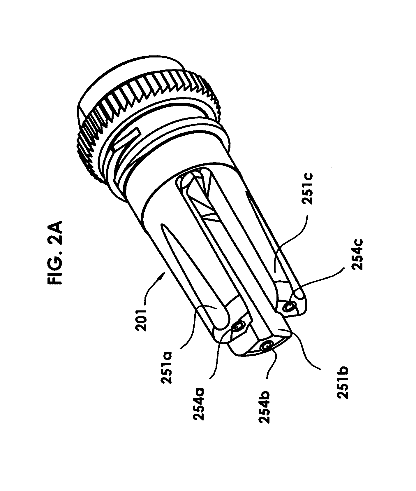
[0021] FIG. 2A depicts a perspective view of another flash suppressor of the invention using metal balls as harmonic dampers.
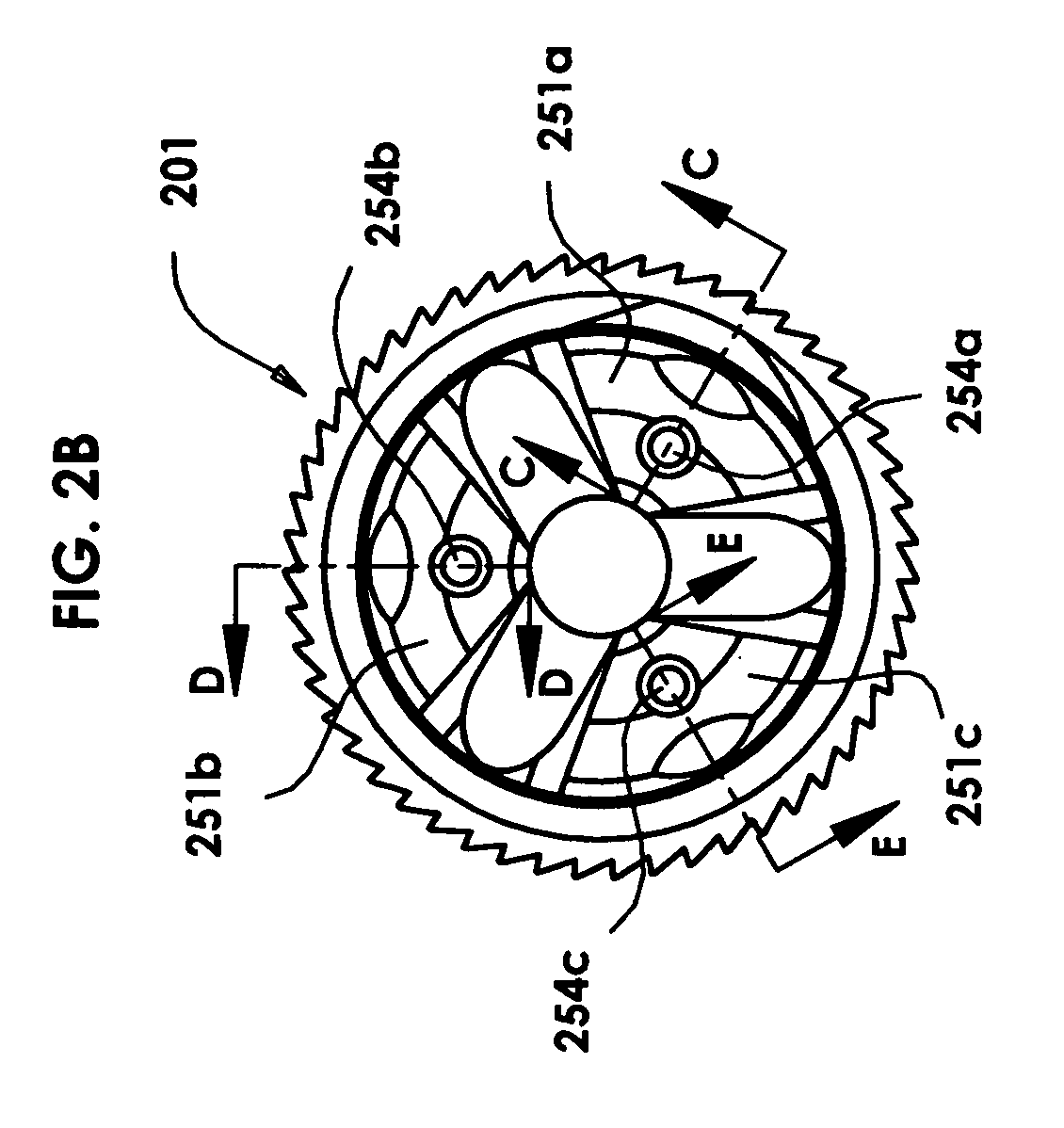
[0022] FIG. 2B depicts a front end view of the flash suppressor of FIG. 2A.
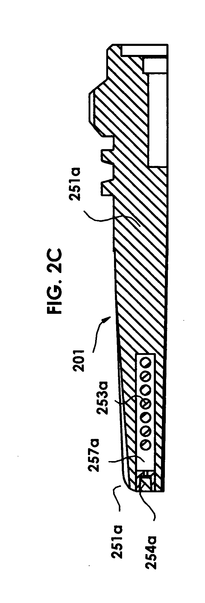
[0023] FIG. 2C depicts a cross sectional view of the flash suppressor of FIG. 2B at C-C.
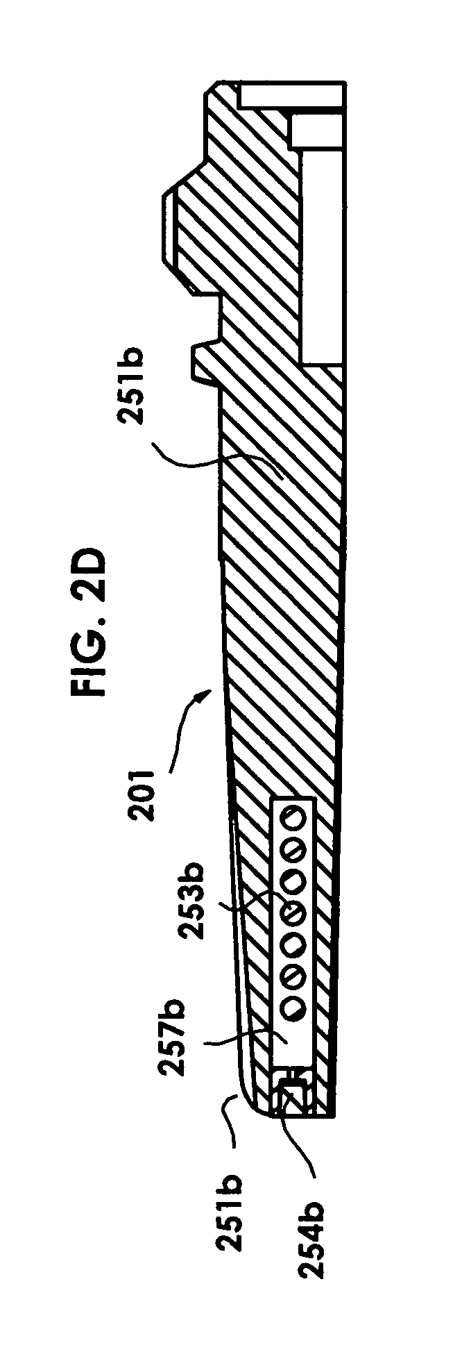
[0024] FIG. 2D depicts a cross sectional view of the flash suppressor of FIG. 2B at D-D.
[0025] FIG. 2E depicts a cross sectional view of the flash suppressor of FIG. 2B at E-E.
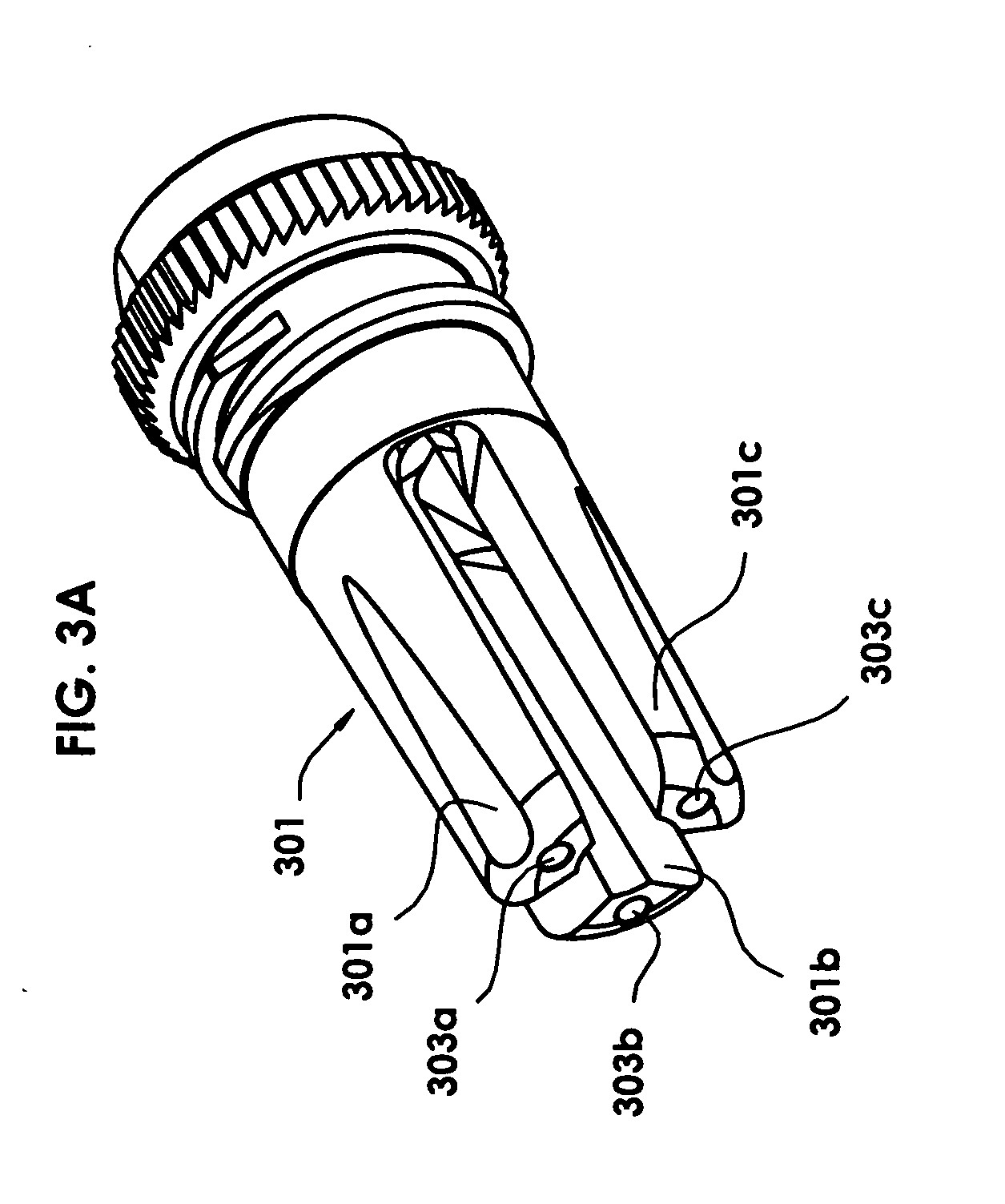
[0026] FIG. 3A depicts a perspective view of another flash suppressor of the invention using matrix as a damper.
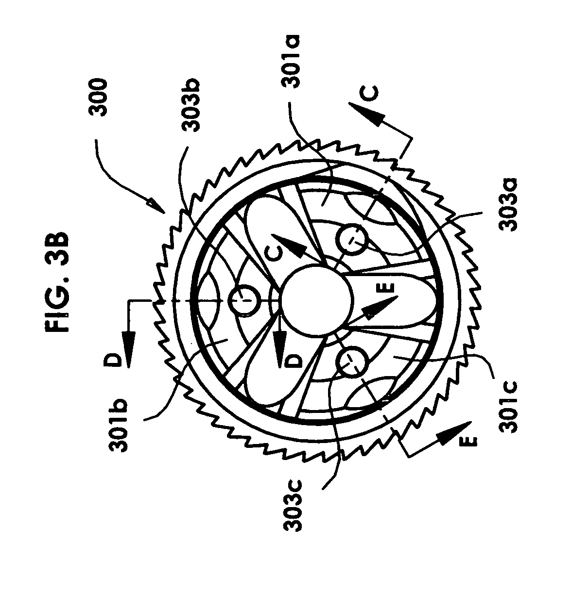
[0027] FIG. 3B depicts a front end view of the flash suppressor of FIG. 3A.
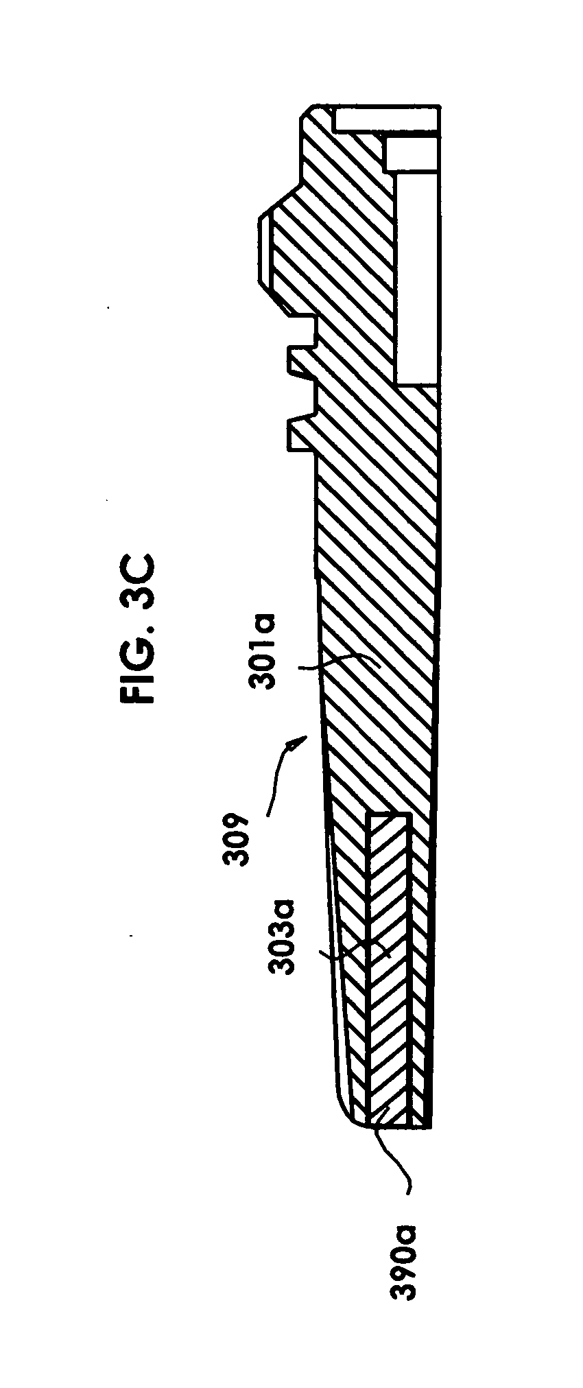
[0028] FIG. 3C depicts a cross sectional view of the flash suppressor of FIG. 3B at C-C.
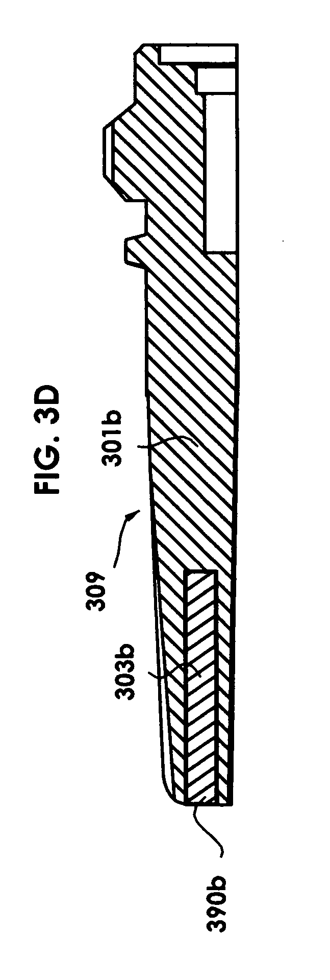
[0029] FIG. 3D depicts a cross sectional view of the flash suppressor of FIG. 3B at D-D.
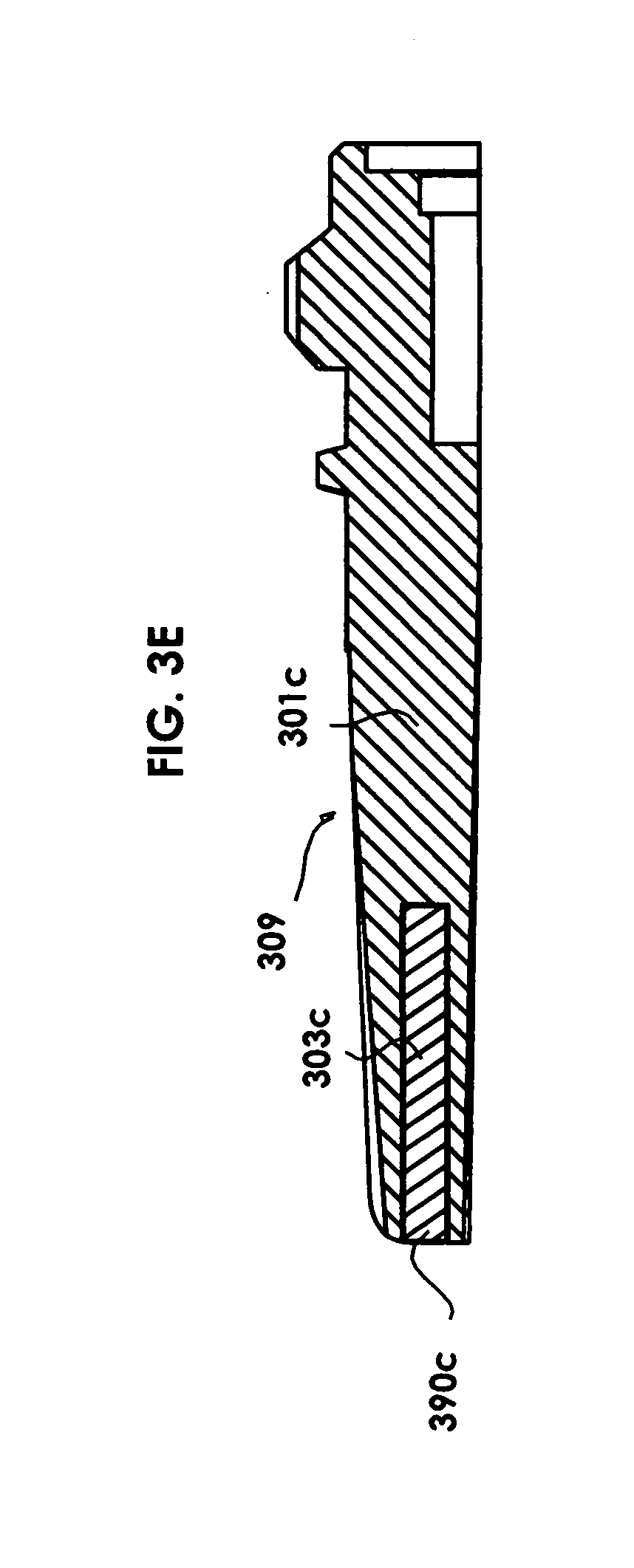
[0030] FIG. 3E depicts a cross sectional view of the flash suppressor of FIG. 3B at E-E.
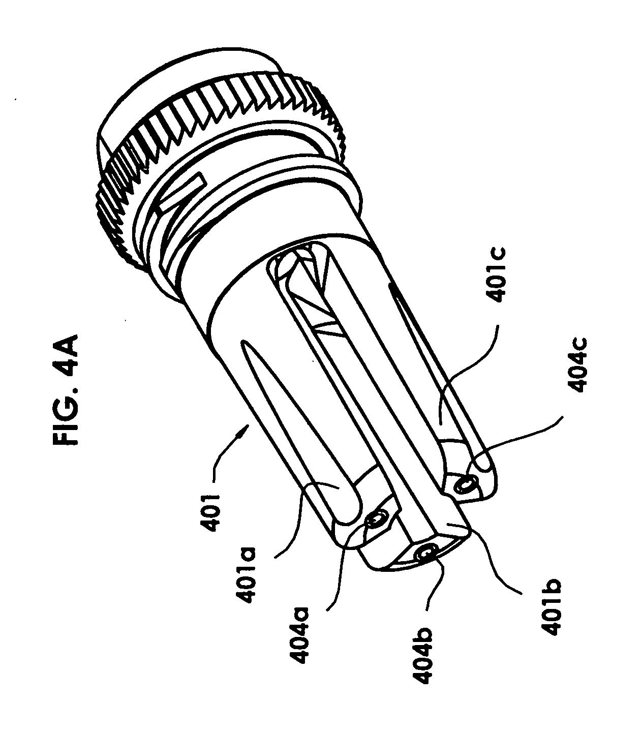
[0031] FIG. 4A depicts a perspective view of another flash suppressor of the invention using rods of equal lengths as dampers, placed into cavities of equal depths. In order to vary the centers of mass of the prongs (and the prong masses), rods of different specific gravities are used, resulting in prongs with different harmonics which are thus harmonically de-tuned.
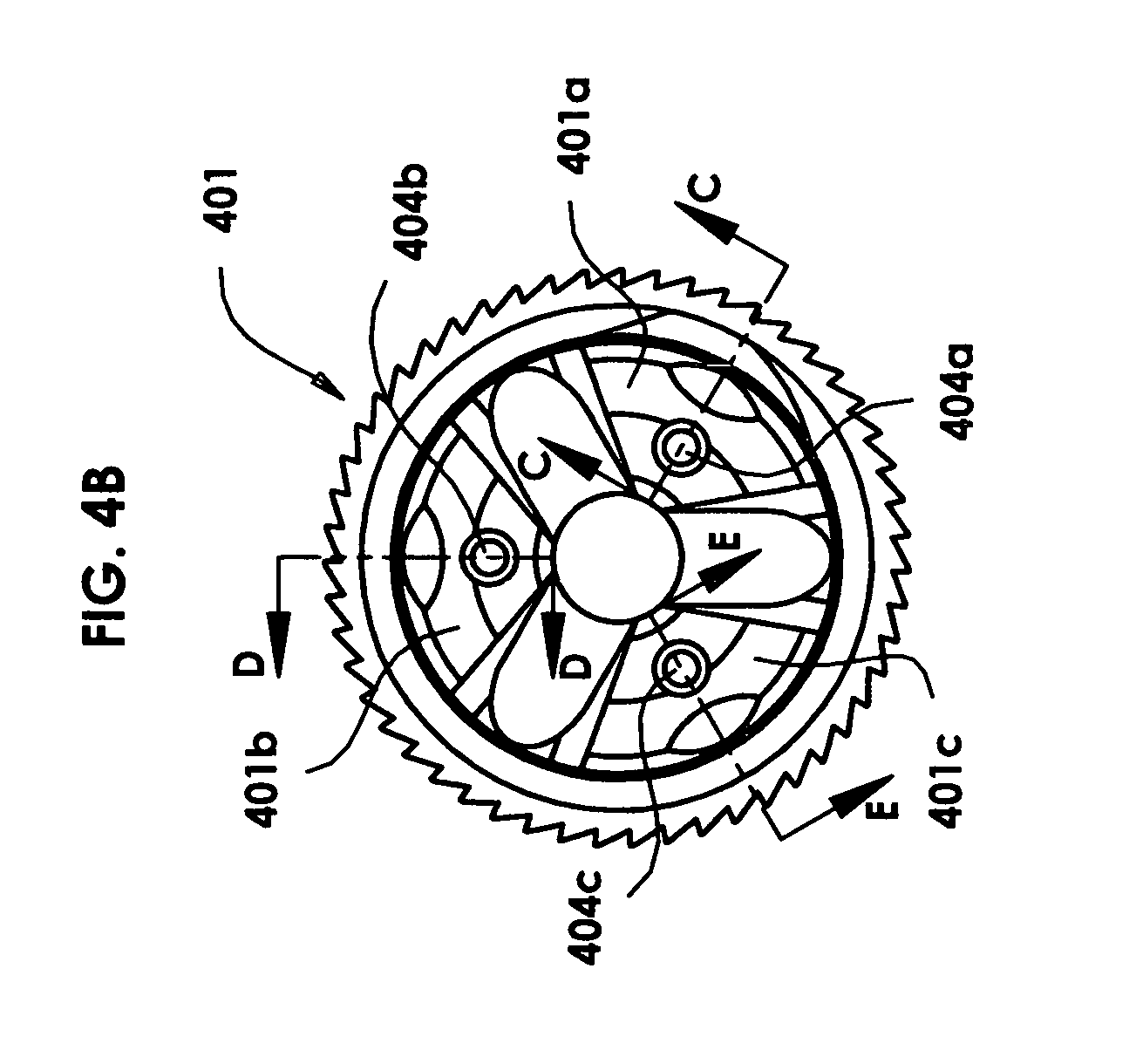
[0032] FIG. 4B depicts a front end view of the flash suppressor of FIG. 4A.
[0033] FIG. 4C depicts a cross sectional view of the flash suppressor of FIG. 4B at C-C.
[0034] FIG. 4D depicts a cross sectional view of the flash suppressor of FIG. 4B at D-D.
[0035] FIG. 4E depicts a cross sectional view of the flash suppressor of FIG. 4B at E-E.
[0036] FIG. 5A depicts a perspective view of another flash suppressor of the invention using rods of equal lengths as dampers, placed into cavities of equal depths at unequal locations along the longitudinal axis of the flash suppressor in order to create a harmonically de-tuned flash suppressor. The rods can each be of the same material and the same mass. This results in a flash suppressor with prongs of equal masses and equal lengths but unequal centers of mass and therefore unequal harmonics, resulting in a harmonically de-tuned flash suppressor.
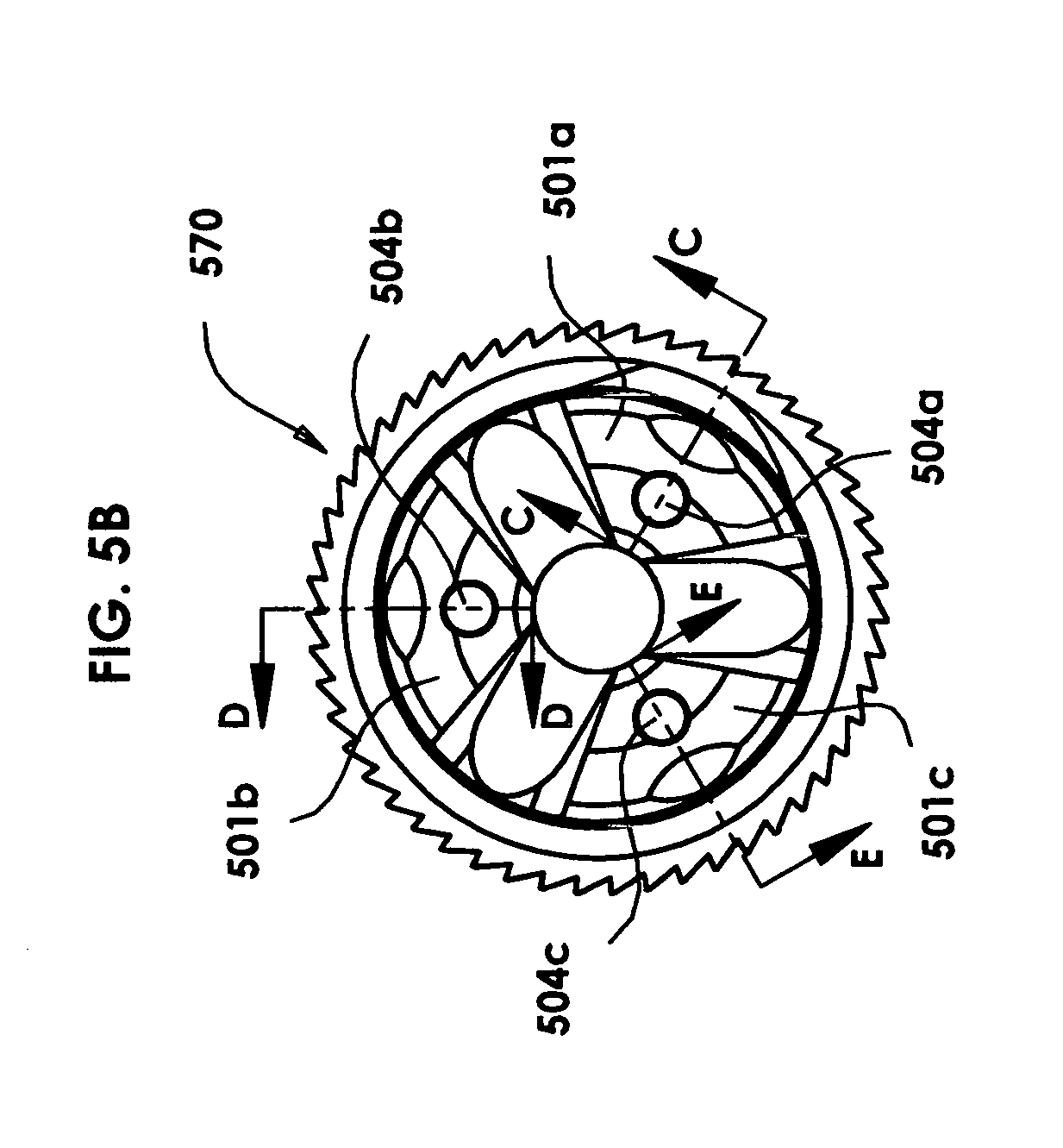
[0037] FIG. 5B depicts a front end view of the flash suppressor of FIG. 5A.
[0038] FIG. 5C depicts a cross sectional view of the flash suppressor of FIG. 5B at C-C.
[0039] FIG. 5D depicts a cross sectional view of the flash suppressor of FIG. 5B at D-D.
[0040] FIG. 5E depicts a cross sectional view of the flash suppressor of FIG. 5B at E-E.
DETAILED DESCRIPTION
[0041] There are many varied implementations of the inventive concept covered by the patent claims, several of which are described below.
[0042] One implementation of the harmonically de-tuned flash suppressor of the invention involves creating a cavity in each of the prongs of the flash suppressor. Each cavity is responsible for the same amount of mass removed from its prong as each other cavity, so that the prongs each have the same mass. The prongs also each have the same length. However, each cavity may be of a different width and depth, or may otherwise vary in dimensions from the other prongs, so that the distribution of material along the prong is different in each prong, resulting in a different center of mass of each prong. A different center of mass for each prong will yield a different fundamental harmonic for each prong, which gives the user a harmonically de-tuned flash hider that does not ping when used in conjunction with a sound suppressor. The resulting flash hider has prongs which can be described as having (a) the same masses as each other, (b) the same lengths, but (c) different centers of gravity and (d) different harmonics. The designer can go one step further and select the dimensions and placement of the cavities to achieve harmonic interference among the prongs, if desired.
[0043] Another implementation of the harmonically de-tuned flash suppressor of the invention involves creating a cavity in each of the prongs of the flash suppressor. Each cavity is responsible for a different amount of mass removed from its prong than from each other cavity, so that the prongs each have a different mass. The prongs each have the same length as each other prong. The different masses of each prong results in a different center of mass of each prong. A different center of mass for each prong will yield a different fundamental harmonic for each prong, which gives the user a harmonically de-tuned flash hider that does not ping when used in conjunction with a sound suppressor. The resulting flash hider has prongs which can be described as having (a) different masses from each other prong, (b) the same lengths, but (c) different centers of gravity and (d) different harmonics. The designer can go one step further and select the dimensions and placement of the cavities to achieve harmonic interference among the prongs, if desired.
[0044] Another implementation of the harmonically de-tuned flash suppressor of the invention involves creating a cavity in all but one of the prongs of the flash suppressor. Each cavity is responsible for a different amount of mass removed from its prong than from each other cavity, so that the prongs each have a different mass. The prongs each have the same length as each other prong. The different masses of each prong results in a different center of mass of each prong. A different center of mass for each prong will yield a different fundamental harmonic for each prong, which gives the user a harmonically de-tuned flash hider that does not ping when used in conjunction with a sound suppressor. The resulting flash hider has prongs which can be described as having (a) different masses of each prong, (b) the same lengths, but (c) different centers of gravity and (d) different harmonics. The designer can go one step further and select the dimensions and placement of the cavities to achieve harmonic interference among the prongs, if desired.
[0045] Another implementation of the harmonically de-tuned flash suppressor of the invention involves creating a harmonic damper cavity or payload cavity in a plurality of the prongs of the flash suppressor. Each cavity is of the same size. Into each harmonic damper or payload cavity a payload or harmonic damper may be secured in place in a non-movable position. Securing the payload may be accomplished by screwing, welding, gluing, friction fit or other securement. The payloads can each be of the same mass but place in different locations within the payload cavity. The prongs each have the same length as each other prong. The different locations of the payloads results in a different center of mass of each prong. A different center of mass for each prong will yield a different fundamental harmonic for each prong, which gives the user a harmonically de-tuned flash hider that does not ping when used in conjunction with a sound suppressor. The resulting flash hider has prongs which can be described as having (a) same masses of each prong, (b) the same lengths, but (c) different centers of gravity and (d) different harmonics. The designer can go one step further and select the dimensions and placement of the cavities to achieve harmonic interference among the prongs, if desired.
[0046] Another implementation of the harmonically de-tuned flash suppressor of the invention involves creating a harmonic damper cavity or payload cavity in a plurality of the prongs of the flash suppressor. Each cavity is of a different size. Into each harmonic damper or payload cavity a payload or harmonic damper may be secured in place in a non-movable position. Securing the payload may be accomplished by screwing, welding, gluing, friction fit or other securement. The payloads are each of a different mass to balance out the masses lost due to the payload cavities, resulting in prongs of equal masses. The payloads are placed in different locations within the payload cavities. The different locations of the payloads results in a different center of mass of each prong. A different center of mass for each prong will yield a different fundamental harmonic for each prong, which gives the user a harmonically de-tuned flash hider that does not ping when used in conjunction with a sound suppressor. The resulting flash hider has prongs which can be described as having (a) same masses of each prong, (b) the same lengths, but (c) different centers of gravity and (d) different harmonics. The designer can go one step further and select the dimensions and placement of the cavities to achieve harmonic interference among the prongs, if desired.
[0047] Another implementation of the harmonically de-tuned flash suppressor of the invention involves creating a harmonic damper cavity or payload cavity in a plurality of the prongs of the flash suppressor. Into each harmonic damper or payload cavity a payload or harmonic damper may placed. The harmonic dampers are not secured into position, and can slide along the interior of the payload cavity. The payload cavity is closed at the end so that the payload does not escape. When the firearm is fired, the flash suppressor experiences rearward motion due to recoil. The rearward motion of the flash suppressor tends to cause the harmonic dampers to strike the distal or front end of the flash suppressor. At the moment that the harmonic dampers strike the distal end of the flash suppressor, the harmonics of the prongs are set. Before that, the harmonics are variable or indeterminate. When the harmonics are set, the prongs each have a different center of mass to yield different harmonics for each prong, which gives the user a harmonically de-tuned flash hider that does not ping when used in conjunction with a sound suppressor. The payload cavities and payloads may be selected so that the prongs each have the same or different masses, as desired. The payloads may be solid, liquid or gas. If solid, the payloads may be one or more discrete objects. Alternatively, each payload may be a different material from each other payload, such as gas in one payload cavity, steel balls in another payload cavity, and mercury in a third payload cavity.
[0048] Another implementation of the harmonically de-tuned flash suppressor of the invention involves creating a cavity in at least some of, and perhaps each of the prongs of the flash suppressor. A harmonic damper or payload is placed into at least some of those prong cavities. Each cavity may be of the same dimensions and volume as each other cavity, and each damper object may be of the same mass and dimensions as each other damper object (or otherwise). In that situation, the damper objects could be fixed at different longitudinal locations in each prong, resulting in (a) each prong having the same length as each other prong, (b) each prong having the same mass as each other prong, (c) each prong having a different center of gravity from each other prong, and (d) each prong having a different fundamental resonance harmonic from each other prong, resulting in a harmonically de-tuned flash suppressor.
[0049] Another implementation of the harmonic damper mechanism involves creating a cavity or receptacle in each of the prongs of the flash suppressor, wherein each cavity is of the same dimensions and volume. Then a damper object is placed into each cavity of each prong. In this embodiment of the invention, each damper object has a different mass (and perhaps different dimensions) from each other damper object, but each damper object is placed in the same relative position in each cavity. In this embodiment of the invention, (a) each prong has the same length as each other prong, (b) each prong has a different mass from each other prong, (c) each prong has a different center of gravity from each other prong, and (d) each prong has a different fundamental resonance harmonic from each other prong, resulting in a harmonically de-tuned flash suppressor.
[0050] Yet another implementation of the harmonic damper mechanism involves creating a cavity or receptacle in N-1 of the prongs of the flash suppressor, where the flash suppressor has N prongs, and N is an integer. Each of the cavities created will be different dimension and volume. No damper object is placed in the cavities as the cavities themselves cause the flash suppressor prongs to be of different masses and different centers of gravity, and therefore to be harmonically de-tuned.
[0051] Another implementation of the harmonic damper mechanism of the invention involves creating a cavity or receptacle in each of the prongs of the flash suppressor, and placing a damper object in at least some of those cavities. The dimensions and volumes of the cavities are matched to the masses of the damper objects so that in the resulting flash suppressor, (a) each prong has the same length as each other prong, (b) each prong has the same mass as each other prong, (c) each prong has a different center of gravity from each other prong, and (d) each prong has a different fundamental resonance harmonic from each other prong, resulting in a harmonically de-tuned flash suppressor. This may be achieved by balancing the dimensions and volumes of the cavities with the masses of the damper objects so that the resulting finished prongs each have the same mass but a different center of gravity. Each damper object may be of the same or different dimension and the same or different masses as long as the finished prong masses remain the same, yet each prong has a different center of gravity. The harmonic damper objects may be each of the same size or each of a different size, and they may be each of the same material, or the materials may be varied, as long as the resulting prongs are each of the same mass but are harmonically de-tuned from each other.
[0052] In another embodiment of the invention, a prong-type flash hider has a body and a plurality of prongs extending distally from the body. The body is attachable to a muzzle of a firearm. The body can be structurally configured to allow a sound suppressor to be attached to the flash suppressor. In the finished harmonically de-tuned flash suppressor, each prong is of the same length as each other prong, and each prong is of the same mass as each other prong, but each prong has a different center of gravity from each other prong and each prong has a different fundamental harmonic from each other prong. The difference in centers of mass and harmonics are achieved by at least a plurality of the prongs each having a load bearing cavity, and within those cavities, each has a payload. The sizes of the load bearing cavities and the masses of the payloads may be varied from prong to prong as long as the resulting masses of the prongs remain equal. The locations and sizes of the load bearing cavities may be varied from prong to prong as long as the resulting centers of gravity of the prongs are each different from each other. The load bearing cavities may be of any desired shape or location. The payloads may be of any desired material, such as solids, liquids, or gases. Example payloads include metal rods, metal spheres, loose metal particles, ceramics, oil, mercury, alcohol, polymers, other hydrocarbons, matrix materials, wood, other natural materials, nanomaterials, compressed gas, non-compressed gas and a vacuum. The payloads may be fixed in place within the load bearing cavities or they may be allowed to freely move within the load bearing cavities.
[0053] In another embodiment of the invention, self-centering payloads cane be installed in the prong receptacles. When the firearm moves rearward during recoil, the payloads initially move, but eventually strike the end of the prongs and are temporarily fixed in that location. It is the fixed location of the payloads which determines the centers of gravity of each prong. The centers of gravities of the prongs may differ from each other for a harmonically de-tuned flash suppressor.
[0054] The cavities in the prongs of the flash suppressor may be sealed, plugged, welded or left open, as desired. The damper objects may be held in the cavities by any desired means such as by being threaded, friction fit, welded, mechanically interlocked, epoxied or otherwise secured, or they may be allowed to move or float within the cavities. The materials of the damper objects may be the same as the materials of the prongs, or they may be different materials, as long as at least some of the objects generally described above are achieved. Further, the material of the damper objects can be of a higher or lower specific gravity than the material of the prongs, as desired. If the material of the damper objects has a significantly greater specific gravity than the specific gravity of the flash suppressor prong material, then a greater variance in center of gravity of each prong and thus a greater variance in fundamental harmonic frequency of each prong can be established in the finished flash suppressor.
[0055] Referring to FIGS. 1A-1E, one example embodiment of the invented harmonically de-tuned flash suppressor usable with a sound suppressor is depicted 101. The flash suppressor 101 has a body section 102 which accommodates mounting to the muzzle of a rifle barrel (not shown), and which accommodates mounting of a sound suppressor (not shown) to the sound suppressor 101. The mounting of the flash suppressor to the muzzle of a firearm may be accomplished by use of threads or other mechanical fitment, welding, or other attachment means. Threads 103 or other attachment means will accommodate mounting of a sound suppressor to the flash suppressor 101.
[0056] The flash suppressor 101 also has a plurality of prongs which are shaped and structurally configured to minimize flash from the discharge of a rifle. In this example embodiment of the invention, three (3) prongs 104a, 104b and 104c are shown, although a different number of prongs may be used in different embodiments of the invention. Each prong is depicted as being of approximately equal length to the length of each other prong. Longitudinally placed within the distal end of each prong 104a, 104b and 104c is a cavity 105a, 105b and 105c. The cavities depicted in this embodiment of the invention each have the same radial dimension but a different depth and therefore a different volume, so that the mass of each prong differs from the mass of each other prong after formation of the cavities. The differing cavity volumes result in a different center of gravity for each prong, which yields a different harmonic resonance for each prong compared to each other prong. The cavity ends may be left open or sealed as desired. In this embodiment of the invention, no harmonic damper or payload is placed within the cavities. Alternatively, dampers or payloads could be placed in the cavities if desired. The flash suppressor 101 also has a bore 130 through which a bullet may pass without touching the prongs.
[0057] Referring to FIGS. 2A-2E, another example embodiment of the invented harmonically de-tuned flash suppressor usable with a sound suppressor is depicted 201. The flash suppressor 201 has a plurality of prongs 251a, 251b and 251c which are shaped and structurally configured to minimize flash from the discharge of a rifle. The prongs are shown to have load carrying cavities 257a, 257b and 257c . The load carrying cavities may be sealed with a plug, screw, welding or other seal 254a, 254b an 254c. The load carrying cavity seal keeps the payload 253a, 253b and 253c from escaping from the load carrying cavity.
[0058] The payloads may be established in any configuration desired. For example, the payloads can be a plurality of discrete objects such as metal balls. Or the payloads can be a liquid such as oil or mercury. Or the payloads can be a gas or a vacuum. Alternatively, the payload can vary from one payload cavity to another. In the drawings, the payloads are shown to be round balls, such as metal, ceramic or rubber balls. The payloads can be fixed in place within the cavities, or the payloads can be allowed to move within the cavities. For example, the balls could be pressed into place within the cavities, or the payloads would move within the cavities until they are forced against the payload cavity plugs under recoil, thus setting the center of gravity of the prong and thus its harmonic. One simple way to vary centers of gravity of the prongs is to have a different number of balls in each payload cavity. The masses of the plugs could be selected to balance out the masses of the payloads so that the resulting prongs each has the same mass as each other prong. The result is a flash suppressor whose prongs each have a different harmonic than each other prong.
[0059] Referring to FIGS. 3A-3E, another example embodiment of the invented harmonically de-tuned flash suppressor usable with a sound suppressor is depicted 300. The flash suppressor 300 has a plurality of prongs 301a, 301b and 301c which are shaped and structurally configured to minimize flash from the discharge of a rifle. The prongs are shown to have load carrying cavities 303a, 303b and 303c. The load carrying cavities may have payloads 390a, 390b and 390c within them. The payloads may be fixed within the load carrying cavities by a press fit, screwing, epoxy, welding or other sealing means. Each payload may be the same material as the prongs or a different material. If different materials are used, then the specific gravities of the payloads may vary from one another. The payloads may each be of the same mass as each other payload, or otherwise. The size and shape of each load carrying cavity and each payload may be different than the others, yet still result in prongs of equal masses but differing centers of gravity and differing fundamental harmonics.
[0060] The payloads may be established in any configuration desired. For example, the payloads can be a plurality of discrete objects such as metal balls. Or the payloads can be a liquid such as oil or mercury. Or the payloads can be a gas or a vacuum. Alternatively, the payload can vary from one payload cavity to another. In the drawings, the payloads are shown to be round balls, such as metal, ceramic or rubber balls. The payloads can be fixed in place within the cavities, or the payloads can be allowed to move within the cavities. For example, the balls could be pressed into place within the cavities, or the payloads would move within the cavities until they are forced against the payload cavity plugs under recoil, thus setting the center of gravity of the prong and thus its harmonic. One simple way to vary centers of gravity of the prongs is to have a different number of balls in each payload cavity. The masses of the plugs could be selected to balance out the masses of the payloads so that the resulting prongs each has the same mass as each other prong. The result is a flash suppressor whose prongs each have a different harmonic than each other prong. The payloads may be made of a matrix material, such as an epoxy embedded with metal flakes. The matrix material can be used to achieve prongs with differing harmonics from each other so that the resulting flash suppressor is harmonically de-tuned. The material may any of countless matrix materials known. For example, the matrix material could be a resin with heavy metal balls embedded in it. Or the matrix material could be a resin with microspheres embedded in it. Or the matrix material could be foamed. The matrix material could result in each prong of the flash suppressor having the same mass or different mass as each other prong as desired. Or the matrix material in each cavity could be a different matrix material from the matrix material in each other prong so that each prong has a different mass from each other prong. For example, the matrix material in prong 301a could be epoxy embedded with lead flakes. The matrix material in prong 302b could be epoxy embedded with microspheres. And the matrix material in prong 302c could be epoxy embedded with carbon fibers. As used herein, matrix materials are materials made from two or more constituent materials with significantly different physical or chemical properties, that when combined, produce a material with characteristics different from the individual components. The individual components remain separate and distinct within the finished structure, as opposed to chemically bonding with each other. Modern matrix materials include fiber-reinforced polymers and metal composites.
[0061] FIGS. 4A-4E depict a flash suppressor 401 that has a plurality of prongs 401a, 401b and 401c , each prong having a load bearing cavity 402a, 402b and 402c of equal volume and equal depth. Into the cavities are place harmonic damper rods 403a, 403b and 403c of equal lengths. In order to vary the centers of gravity of the prongs and thereby de-tune the harmonics of the prongs, it is necessary for the rods to each have a different specific gravity. That would also result in the prongs each having different masses from each other. The rods are depicted as being seated at the bottoms 420a, 420b and 420c of the cavities, although other placement could be used, or the rods could be allowed to freely move within the load bearing cavities. Each cavity has a plug 404a, 404b and 404c to prevent is payload from escaping. Plugs also help to improve the appearance of the harmonically de-tuned flash hider.
[0062] Referring to FIGS. 5A-5E, another flash suppressor 570 of the invention with prongs 501a, 501b and 501c that use rods 503a, 503b and 503c of equal lengths as dampers, the rods being fixed into prong cavities 504a, 504b and 504c of equal depths at unequal locations along the longitudinal axis of the flash suppressor in order to create a harmonically de-tuned flash suppressor. This results in a flash suppressor with prongs of equal masses and equal lengths but unequal centers of mass and unequal harmonics. In this example embodiment, the dampers are in the form of cylindrical rods. The rods could be pressed into place, screwed into place or otherwise affixed in their desired positions. The rods could each be made from the same material as each other rod. The rods could be made of the same material as the prongs or from a different material. The cavities are each designed to accept placement of a payload or harmonic damper therein. This placement of the dampers results in prongs which each have a different center of gravity and therefore a different harmonic resonance, thereby creating a harmonically de-tuned flash suppressor.
[0063] Unused voids remain in the prong payload cavities. In this example embodiment, the dampers are depicted as each being of the same dimensions as each other, each being of the same mass, and each being of the same material, although that would not necessarily be the case in other embodiments of the invention. The cavities are depicted as being unsealed, but they could be closed with a cap, plug, screw, welding, epoxy or other device as desired. Press-fit dampers are held in place by friction with the walls of the cavities. Or they could be otherwise affixed.
[0064] While the present invention has been illustrated and described with respect to a number of specific example embodiments, those skilled in the art will appreciate that variations and modifications may be made without departing from the fundamental principles of the invention as herein described, illustrated and claimed. The present invention may be implemented in a variety of different forms without departing from its fundamental characteristics or spirit. The described embodiments are to be considered as illustrative and are in no way intended to be restrictive of the scope of the invention. The scope of the invention is defined by the appending claims rather than the foregoing description. All changes which come within the meaning and range of equivalency of the claim are to be embraced within their scope.
* * * * *
References
D00000
D00001
D00002
D00003
D00004
D00005
D00006
D00007
D00008
D00009
D00010
D00011
D00012
D00013
D00014
D00015
D00016
D00017
D00018

D00019

D00020

D00021

D00022
D00023

D00024

XML
uspto.report is an independent third-party trademark research tool that is not affiliated, endorsed, or sponsored by the United States Patent and Trademark Office (USPTO) or any other governmental organization. The information provided by uspto.report is based on publicly available data at the time of writing and is intended for informational purposes only.
While we strive to provide accurate and up-to-date information, we do not guarantee the accuracy, completeness, reliability, or suitability of the information displayed on this site. The use of this site is at your own risk. Any reliance you place on such information is therefore strictly at your own risk.
All official trademark data, including owner information, should be verified by visiting the official USPTO website at www.uspto.gov. This site is not intended to replace professional legal advice and should not be used as a substitute for consulting with a legal professional who is knowledgeable about trademark law.