Tube Structures For Heat Exchanger
Taras; Michael F. ; et al.
U.S. patent application number 14/769503 was filed with the patent office on 2015-12-31 for tube structures for heat exchanger. This patent application is currently assigned to Carrier Corporation. The applicant listed for this patent is CARRIER CORPORATION. Invention is credited to Luis Felipe Avila, James T. Beals, Changsheng Guo, Loren D. Hoffman, Qinghua Huang, Eric Konkle, Michael W. Samko, Michael F. Taras, Melkamu Woldesemayat.
| Application Number | 20150377563 14/769503 |
| Document ID | / |
| Family ID | 50179946 |
| Filed Date | 2015-12-31 |

| United States Patent Application | 20150377563 |
| Kind Code | A1 |
| Taras; Michael F. ; et al. | December 31, 2015 |
TUBE STRUCTURES FOR HEAT EXCHANGER
Abstract
A heat exchanger includes a plurality of fins and a plurality of tubes passing a fluid therethrough, extending through the plurality of fins and radially expanded into an interference fit therewith. At least one tube of the plurality of tubes includes an outer diameter, an inner diameter, and a plurality of ridges extending from the inner diameter inwardly into an interior of the tube. A tube internal surface area per unit of length of the tube multiplied by the ratio of the outer diameter and tube wall thickness is equal to or greater than about 30.0.
| Inventors: | Taras; Michael F.; (Fayetteville, NY) ; Woldesemayat; Melkamu; (Liverpool, NY) ; Avila; Luis Felipe; (Manlius, NY) ; Guo; Changsheng; (South Windsor, CT) ; Samko; Michael W.; (Collierville, TN) ; Hoffman; Loren D.; (Jamestown, IN) ; Beals; James T.; (West Hartford, CT) ; Huang; Qinghua; (Shanghai, CN) ; Konkle; Eric; (Plainfield, IN) | ||||||||||
| Applicant: |
|
||||||||||
|---|---|---|---|---|---|---|---|---|---|---|---|
| Assignee: | Carrier Corporation Farmington CT |
||||||||||
| Family ID: | 50179946 | ||||||||||
| Appl. No.: | 14/769503 | ||||||||||
| Filed: | February 10, 2014 | ||||||||||
| PCT Filed: | February 10, 2014 | ||||||||||
| PCT NO: | PCT/US2014/015550 | ||||||||||
| 371 Date: | August 21, 2015 |
Related U.S. Patent Documents
| Application Number | Filing Date | Patent Number | ||
|---|---|---|---|---|
| 61767506 | Feb 21, 2013 | |||
| Current U.S. Class: | 165/183 |
| Current CPC Class: | F28F 13/187 20130101; F28D 2021/0068 20130101; F28F 1/32 20130101; F28F 1/40 20130101 |
| International Class: | F28F 1/40 20060101 F28F001/40 |
Claims
1. A heat exchanger comprising: a plurality of fins; a plurality of tubes passing a fluid therethrough, extending through the plurality of fins and radially expanded into an interference fit therewith, a least one tube of the plurality of tubes including: an outer diameter; an inner diameter; and a plurality of ridges extending from the inner diameter inwardly into an interior of the tube; wherein a tube internal surface area per unit of length of the tube multiplied by the ratio of the outer diameter to a tube wall thickness between the outer diameter and the inner diameter, is equal to or greater than about 30.0.
2. The heat exchanger of claim 1, wherein the plurality of ridges extend substantially axially along a length of the tube.
3. The heat exchanger of claim 1, wherein the plurality of ridges extend helically along a length of the tube.
4. The heat exchanger of claim 1, wherein the tube internal surface area per unit of length of the tube multiplied by the ratio of the outer diameter to the tube wall thickness between the outer diameter and the inner diameter, is equal to about 33.4.
5. The heat exchanger of claim 1, wherein an internal free volume of the tube per unit of length confined between said ridges divided by a square of the outer diameter is equal to or greater than 0.040.
6. The heat exchanger of claim 5, wherein a ratio of ridge cross-sectional area to a square of inner diameter is equal to or greater than about 0.0014.
7. The heat exchanger of claim 5, wherein an internal free volume of the tube per unit of length divided by a square of the outer diameter is about 0.047.
8. The heat exchanger of claim 1, wherein a ratio of the outer diameter to the inner diameter is less than or equal to about 1.185.
9. The heat exchanger of claim 1, wherein a ratio of a top width of each ridge to the inner diameter multiplied by the number of ridges is equal to or greater than about 1.60.
10. The heat exchanger of claim 1, wherein: a ratio of ridge cross-sectional area to a square of inner diameter is equal to or greater than about 0.0014; and a ratio of ridge height to inner diameter is equal to or greater than about 0.045.
11. The heat exchanger of claim 1, wherein the plurality of tubes is formed from and aluminum or aluminum alloy.
12. A heat exchanger comprising: a plurality of fins; a plurality of tubes passing a fluid therethrough, extending through the plurality of fins and radially expanded into an interference fit therewith, a least one tube of the plurality of tubes including: an outer diameter; an inner diameter; and a plurality of ridges extending from the inner diameter inwardly into an interior of the tube; wherein an internal free volume of the tube per unit of length confined between said ridges divided by a square of the outer diameter is equal to or greater than 0.040.
13. The heat exchanger of claim 12, wherein an internal free volume of the tube per unit of length confined between said ridges divided by a square of the outer diameter is about 0.047.
14. The heat exchanger of claim 12, wherein a ratio of the outer diameter to the inner diameter is less than or equal to about 1.185.
15. The heat exchanger of claim 12, wherein a ratio of a top width of each ridge to the inner diameter multiplied by a number of ridges in the plurality of ridges is equal to or greater than about 1.60.
16. The heat exchanger of claim 12, wherein: a ratio of ridge cross-sectional area to a square of inner diameter is equal to or greater than about 0.0014; and a ratio of ridge height to inner diameter is equal to or greater than about 0.045.
17. A heat exchanger comprising: a plurality of fins; a plurality of tubes passing a fluid therethrough, extending through the plurality of fins and radially expanded into an interference fit therewith, a least one tube of the plurality of tubes including: an outer diameter; an inner diameter; and a plurality of ridges extending from the inner diameter inwardly into an interior of the tube; wherein a ratio of the outer diameter to the inner diameter is less than or equal to about 1.185.
18. The heat exchanger of claim 17, wherein the ratio of the outer diameter to the inner diameter is less than or equal to about 1.181.
19. The heat exchanger of claim 17, wherein a ratio of a top width of each ridge to the inner diameter multiplied by a number of ridges in the plurality of ridges is equal to or greater than about 1.60.
20. The heat exchanger of claim 17, wherein: a ratio of ridge cross-sectional area to a square of inner diameter is equal to or greater than about 0.0014; and a ratio of ridge height to inner diameter is equal to or greater than about 0.045.
21. A heat exchanger comprising: a plurality of fins; a plurality of tubes passing a fluid therethrough, extending through the plurality of fins and radially expanded into an interference fit therewith, a least one tube of the plurality of tubes including: an outer diameter; an inner diameter; and a plurality of ridges extending from the inner diameter inwardly into an interior of the tube; wherein a ratio of a top width of each ridge to the inner diameter multiplied by a number of ridges in the plurality of ridges is equal to or greater than about 1.60.
22. The heat exchanger of claim 21, wherein: a ratio of ridge cross-sectional area to a square of inner diameter is equal to or greater than about 0.0014; and a ratio of ridge height to inner diameter is equal to or greater than about 0.045.
23. A heat exchanger comprising: a plurality of fins; a plurality of tubes passing a fluid therethrough, extending through the plurality of fins and radially expanded into an interference fit therewith, a least one tube of the plurality of tubes including: an outer diameter; an inner diameter; and a plurality of ridges extending from the inner diameter inwardly into an interior of the tube; wherein: a ratio of ridge cross-sectional area to a square of inner diameter is equal to or greater than about 0.0014; and a ratio of ridge height to inner diameter is equal to or greater than about 0.045.
Description
BACKGROUND
[0001] The subject matter disclosed herein relates to heat exchangers. More specifically, the subject disclosure relates to improved tube structures for a heat exchanger.
[0002] A simplified typical vapor compression refrigeration cycle includes an evaporator, a compressor, a condenser and an expansion device. Refrigerant flow is such that low pressure refrigerant vapor passes through a suction line to the compressor. The compressed refrigerant vapor is pumped to a discharge line that connects to the condenser. A liquid line receives liquid refrigerant exiting the condenser and directs it to the expansion device. A two-phase refrigerant is returned to the evaporator, thereby completing the cycle.
[0003] Two of the main components in a vapor compression cycle are the evaporator and condenser heat exchangers. The most common type of heat exchanger in use is of the round tube plate fin (RTPF) construction type. Historically, the tubes were made of copper while the fins were typically made of aluminum in such heat exchangers. The thermal performance of a heat exchanger, the ability to transfer heat from one medium to another, is inversely proportional to the sum of its thermal resistances. For a typical heating, ventilation, air conditioning and refrigeration (HVAC&R) application using refrigerant inside the tubes and air on the external fin side, the airside thermal resistance contributes 50-70% while refrigerant side thermal resistance is 20-40% and the metal resistance is relatively small and represents only 6-10%. Due to the continuous market pressure and regulatory requirements to make HVAC&R units more compact and cost effective, a lot of effort has been devoted to improving the heat exchanger performance on the refrigerant side as well as the airside.
[0004] Internally enhanced round tubes used in RTPF heat exchangers allow significant heat exchanger thermal performance enhancement by improving refrigerant side heat transfer. These tubes are typically fabricated via extrusion or drawing process and mechanically expanded into the fin pack to assure good metal-to-metal contact between the tubes and the fins. The internally grooved (IG) tube technology is mature for Cu alloys, allowing helically shaped enhancement profiles to be fabricated by the drawing process and expanded without significant tube internal enhancement damage. In recent years, the HVAC&R industry started to move from Cu to Al, primarily due to the cost reasons. The Al alloys have inherently different mechanical properties and the Al IG tubes typically produced by the extrusion manufacturing process have axial enhancements that are not as advanced as helical configurations promoting wetting the entire internal perimeter of the tube by the liquid refrigerant and more efficient annular refrigerant flow at the extended range of refrigerant mass fluxes. Therefore internal enhancements for Al tubes require higher secondary-to-primary heat transfer surface ratios and more compact internally enhanced finned surfaces that, along with the softer Al material, create significant challenges for the expansion process.
BRIEF DESCRIPTION
[0005] In one embodiment, a heat exchanger includes a plurality of fins and a plurality of tubes passing a fluid therethrough, extending through the plurality of fins and radially expanded into an interference fit therewith. At least one tube of the plurality of tubes includes an outer diameter, an inner diameter, and a plurality of ridges extending from the inner diameter inwardly into an interior of the tube. A tube internal surface area enhancement ratio multiplied by the ratio of the tube outer diameter and tube wall thickness is equal to or greater than about 30.0.
[0006] In another embodiment, a heat exchanger includes a plurality of fins and a plurality of tubes passing a fluid therethrough, extending through the plurality of fins and radially expanded into an interference fit therewith. At least one tube of the plurality of tubes includes an outer diameter, an inner diameter, and a plurality of ridges extending from the inner diameter inwardly into an interior of the tube. An internal free volume confined between tube internal surface enhancements per unit of length divided by a square of the outer tube diameter is equal to or greater than 0.040.
[0007] In yet another embodiment, a heat exchanger includes a plurality of fins and a plurality of tubes passing a fluid therethrough, extending through the plurality of fins and radially expanded into an interference fit therewith. At least one tube of the plurality of tubes includes an outer diameter, an inner diameter, and a plurality of ridges extending from the inner diameter inwardly into an interior of the tube. A ratio of the outer tube diameter to the inner tube diameter is less than or equal to about 1.185.
[0008] In another embodiment, a heat exchanger includes a plurality of fins and a plurality of tubes passing a fluid therethrough, extending through the plurality of fins and radially expanded into an interference fit therewith. At least one tube of the plurality of tubes includes an outer diameter, an inner diameter, and a plurality of ridges extending from the inner diameter inwardly into an interior of the tube. A ratio of a top width of each ridge to the inner tube diameter multiplied by a number of ridges in the plurality of ridges is equal to or greater than about 1.60.
[0009] In still another embodiment, a heat exchanger includes a plurality of fins and a plurality of tubes passing a fluid therethrough, extending through the plurality of fins and radially expanded into an interference fit therewith. At least one tube of the plurality of tubes includes an outer diameter, an inner diameter, and a plurality of ridges extending from the inner diameter inwardly into an interior of the tube. A ratio of ridge cross-sectional area to a square of inner diameter is equal to or greater than about 0.0014 and a ratio of ridge height to inner diameter is equal to or greater than about 0.045.
[0010] These and other advantages and features will become more apparent from the following description taken in conjunction with the drawings.
BRIEF DESCRIPTION OF THE DRAWINGS
[0011] The subject matter, which is regarded as the invention, is particularly pointed out and distinctly claimed in the claims at the conclusion of the specification. The foregoing and other features, and advantages of the invention are apparent from the following detailed description taken in conjunction with the accompanying drawings in which:
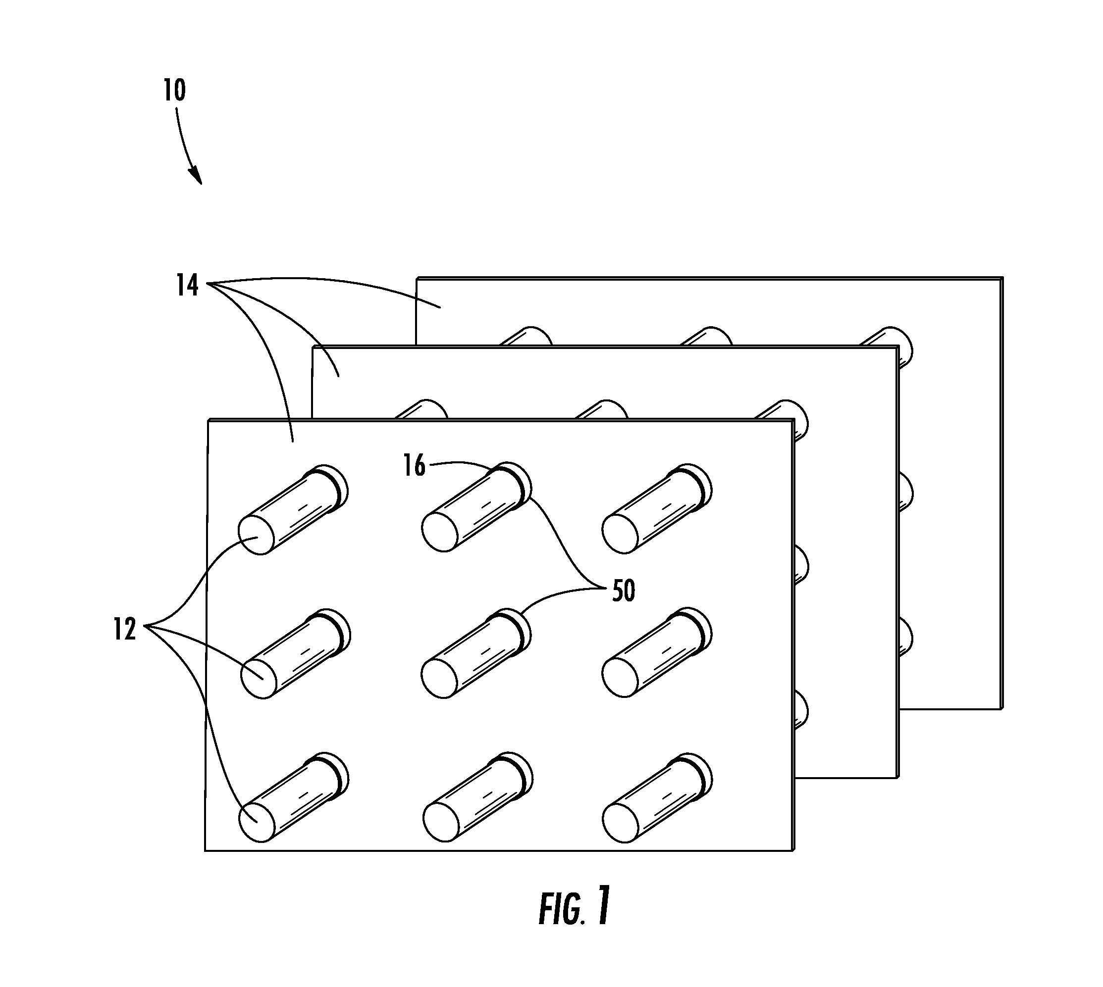
[0012] FIG. 1 is a schematic view of an embodiment of a heat exchanger;
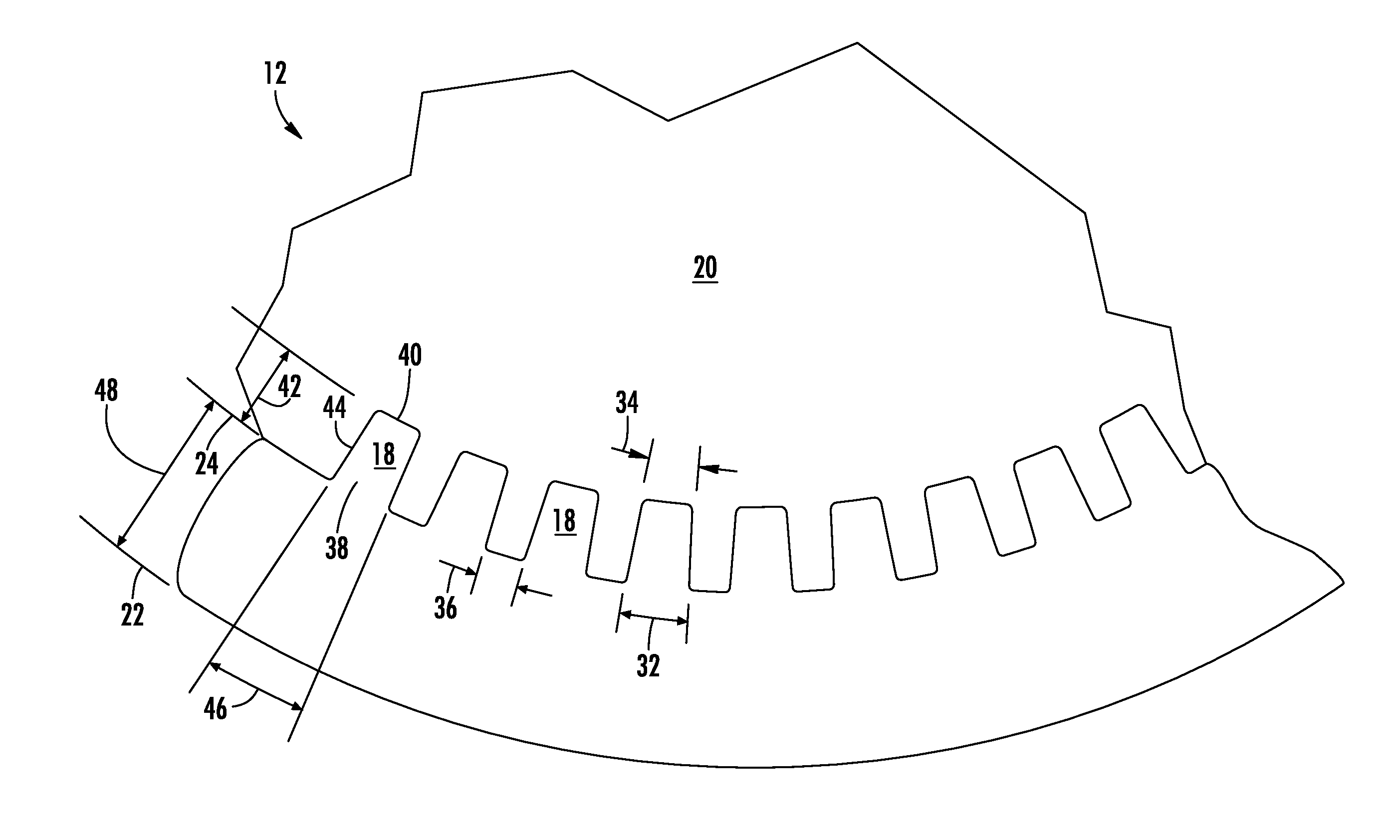
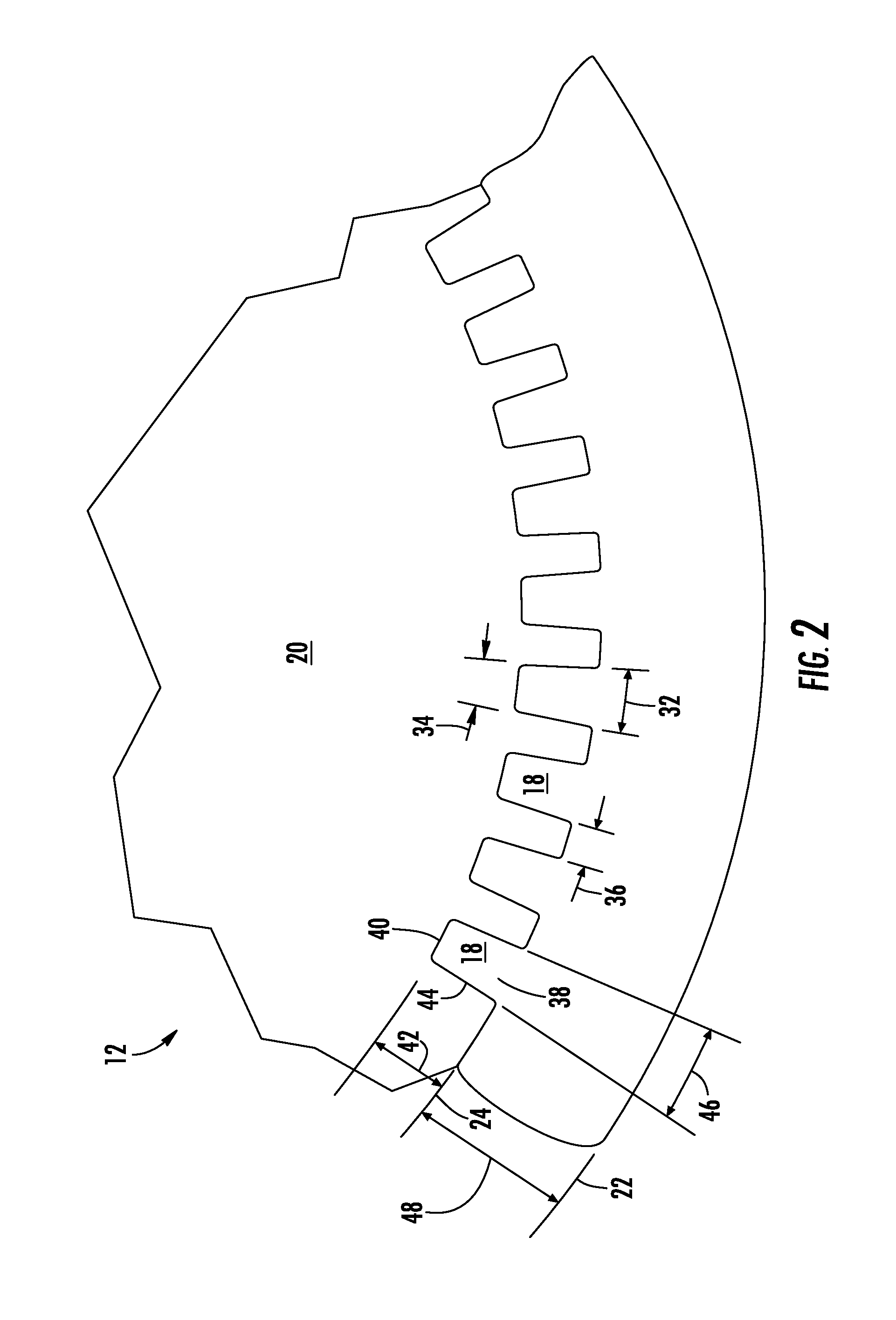
[0013] FIG. 2 is a partial cross-sectional view of an embodiment of a heat exchanger tube;
[0014] FIG. 3 is a perspective view of an embodiment of a heat exchanger tube; and
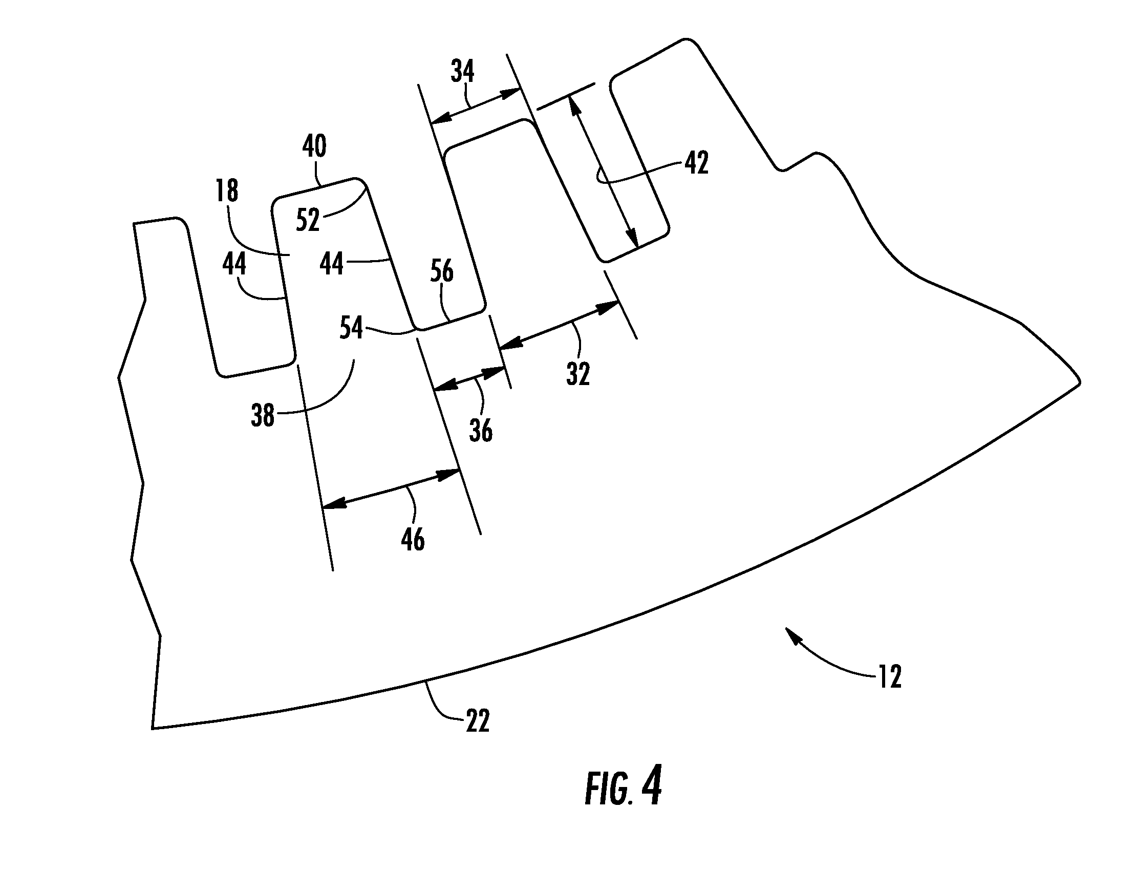
[0015] FIG. 4 is a partial cross-sectional view of another embodiment of a heat exchanger tube.
[0016] The detailed description explains embodiments of the invention, together with advantages and features, by way of example with reference to the drawings.
DETAILED DESCRIPTION
[0017] Shown in FIG. 1 is an embodiment of a round tube plate fin (RTPF) heat exchanger 10, such as one utilized as an evaporator or condenser. The RTPF heat exchanger 10 includes a plurality of tubes 12 and a plurality of fins 14. The plurality of tubes 12 carries a fluid, for example, a refrigerant. Thermal energy is exchanged between the fluid and air flowing past the plurality of fins 14. In some embodiments, the tubes 12 may be formed of an aluminum or aluminum alloy by, for example, an extrusion or drawing process, while in other embodiments, the tubes 12 maybe formed of other materials, for example, copper, Cu--Ni, steel or plastic. In manufacturing the heat exchanger 10, the tubes 12 are inserted into the openings 16 in the fins 14 and mechanically expanded via, for example, one or more bullets inserted into an interior of the tubes 12. The expansion of the tubes 12 ensures sufficient tube 12 to fin 14 contact for heat transfer purposes and also secures the tubes 12 in a predetermined position in the heat exchanger 10, relative to the fins 14.
[0018] FIG. 2 illustrates a partial cross-sectional view of a tube 12 of a heat exchanger 10. The tube 12 includes a plurality of enhancements, or ridges 18 extending into an interior 20 of the tube 12. As shown in FIG. 3, the tube 12 has an outer diameter 22 and an inner diameter 24, with the ridges 18 (also called in-tube fins or enhancements) extending inwardly from the inner diameter 24 into the interior 20 of the tube 12. The ridges 18 extend along a length 26 of the tube 12. In some embodiments, the ridges 18 extend substantially axially, while in other embodiments, the ridges 18 extend helically along the tube 12 at a helix angle 30 with respect to a tube axis 28. Additionally, the ridges 18 have a base width 32 at a base 38 of the ridge 18, a top width 34 at a tip 40, or most radially inwardly portion of the ridge 18, with a groove width 36 spacing between adjacent ridges 18 at the base of adjacent ridges 18. Further, each ridge 18 extends from base 38 to tip 40 defining a ridge height 42, and sides 44 of each ridge 18 may converge at a ridge angle 46, so-called the apex angle of the ridge 18. Referring to FIG. 4, it is to be appreciated that, in some embodiments, each ridge 18 includes a top fillet 52 between the tip 40 and sides 44. In such embodiments, the top width 34 is defined herein as a distance along the tip 40 to a theoretical intersection between the tip 40 and the sides 44. Similarly, in some embodiments, a base fillet 54 may connect sides 44 and groove 56. Base width 32 and groove width 36 are similarly defined using a theoretical intersection point between the sides 44 and the groove 56. It is to be appreciated that while circular tubes having inner and outer diameters are described herein, the present disclosure may also be applied to tubes 12 with non-circular cross-sections.
[0019] The particular features of tubes 12 and ridges 18 described herein all relate to the post-expanded state of the tube 12, or dimensions and features of the tubes 12 and ridges 18 after the tubes 12 have been expanded, securing the tubes 12 to the fins 14.
[0020] An embodiment of the expanded tube 12 has a internal surface area, or internal surface area per unit length defined as:
A=N*[2h/cos (.alpha./2)+a+c] (1)
[0021] where A=the surface area per unit length [0022] N=the number of ridges in the tube [0023] h=the ridge height 42 [0024] .alpha.=the ridge angle 46 [0025] a=ridge top width 34 and [0026] c=groove width 36.
[0027] An unenhanced tube 12 has an internal surface area per unit length A. When A is divided by ID, it results in a surface enhancement ratio, .zeta.. In an embodiment of the tube 12 design, .zeta. is related to a ratio of tube wall thickness 48 and the outer diameter 22 by the expression:
.zeta..gtoreq.30.0*(T.sub.w/OD) (2)
[0028] where T.sub.w=wall thickness 48 and [0029] OD=outer diameter 22.
[0030] The tubes 12 satisfying this requirement in the post-expanded state achieve sufficient tube 12 to fin 14 interference for thermal performance and for securing the tube 12 to the fin 14, while ensuring minimal thermal performance degradation due to distortion of the interior surfaces of the tube 12, such as the groove 36 and ridge 18 structure.
[0031] Liquid layer distribution and containment within the ridged area, or the individual areas between ridges 18, is directly related to the size of this area and has an immediate impact on heat transfer coefficient or thermal resistance of single-phase or two-phase refrigerant flowing inside the tubes 12. Free internal volume per unit of length of the tube 12, S, or the portion of the interior 20 confined between the ridges 18 can be expressed as:
S=N*h.sup.2*(c/h+tan (.alpha./2)) (3)
[0032] for axially enhanced tubes.
[0033] Further, for the tube 12 to have a desired internal heat transfer coefficient or thermal resistance, it is required that in the post-expanded state, a ratio of S to a square of the outer diameter 22 to be greater than or equal to 4%, or:
S/(OD).sup.2>0.040 (4)
[0034] Further, proper mechanical expansion of the tube 12 and tube 12 to fin 14 interference or contact is critical to the overall heat exchanger 10 performance. Thermal contact resistance defines the extent to which the tube 12 is properly expanded onto a fin collar 50 (shown in FIG. 1). Insufficient expansion will lead to poor contact while overexpansion will result in excessive tube shrinkage and may lead to external fin collar 50 splits that will reduce the contact surface area between the tube 12 and fin 14 for heat transfer. A change in the internal diameter 24 is directly related to internal tube surface deformation. Therefore, the expansion process should be controlled such that tube 12 internal surface deformation is reduced and proper tube 12 to fin 14 contact is maintained. Such an optimized process will yield a post-expansion ratio of outer diameter 22 to inner diameter 24 to be less than or equal to 1.185 or
OD/ID.ltoreq.1.185. (5)
[0035] An amount of surface area available for contact with an expansion bullet (not shown) utilized in the interior 20 of the tube 12 is critical in determining an axial force required to be applied to the expansion bullet to achieve the necessary expansion of the tube 12. It is desired to achieve the expansion with the smallest force possible to prevent excessive deformation of ridges 18, buckling and/or galling of interior tube 12 surfaces and features, so it is desired to have wider ridges 18 as compared to the inner diameter 24 so that a lower axial expansion force is required to achieve a desired, uniform radial expansion of the tube 12. As such it is desired that a ratio of the ridge top width 34 to the inner diameter 24 multiplied by the number of ridges 18 is greater than or equal to 1.60 or
a*N/ID.gtoreq.1.60 (6)
[0036] The ridge angle 46 is the key to determining the surface enhancement ratio .zeta., the free volume S contained between ridges 18 and a weight of the tube 12. Surface enhancement ratio .zeta. and free volume S drive thermal performance of the tube 12, while tube weight affects cost of the tube 12. The ridge angle 46 must be designed to yield optimal results given these competing constraints, and defines a cross-sectional area of the ridges 18. Desired ratios of ridge 18 size to inner diameter 24 is expressed as follows:
[(a+b)*h*0.5/(ID).sup.2].gtoreq.0.0014 and (7)
h/ID.gtoreq.0.045 (8)
[0037] In one embodiment of tube 12, the outer diameter 22 is about 7 mm, with an inner diameter 24 of 5.8 mm, resulting in a wall thickness 48 of about 0.6 mm. The tube 12 has 50 ridges 18, each ridge 18 having a ridge height 42 of about 0.32 mm, a base width 32 of about 0.212 mm and a top width 34 of about 0.185 mm. The ridge angle 46 is about 4.8 degrees.
[0038] In this embodiment, utilizing equation (2), requiring that .zeta.*(OD/T.sub.w).gtoreq.30.0, the result is 33.4. Equation (4), requiring that S/(OD).sup.2 is greater than or equal to 0.040, yields the result 0.047. Equation (5), requiring that OD/ID.ltoreq.1.185, results in a ratio of 1.181. The ratio of enhancement top width 34 to inner diameter 24 multiplied by the number of ridges, required to be greater than or equal to 1.60 by expression (6), gives a result of 1.655. Equations (7) and (8) yield results of 0.0016 and 0.046 compared to requirements of greater than or equal to 0.0014 and greater than or equal to 0.045, respectively.
[0039] While the invention has been described in detail in connection with only a limited number of embodiments, it should be readily understood that the invention is not limited to such disclosed embodiments. Rather, the invention can be modified to incorporate any number of variations, alterations, substitutions or equivalent arrangements not heretofore described, but which are commensurate with the spirit and scope of the invention. Additionally, while various embodiments of the invention have been described, it is to be understood that aspects of the invention may include only some of the described embodiments. Accordingly, the invention is not to be seen as limited by the foregoing description, but is only limited by the scope of the appended claims.
* * * * *
D00000
D00001
D00002
D00003
D00004
XML
uspto.report is an independent third-party trademark research tool that is not affiliated, endorsed, or sponsored by the United States Patent and Trademark Office (USPTO) or any other governmental organization. The information provided by uspto.report is based on publicly available data at the time of writing and is intended for informational purposes only.
While we strive to provide accurate and up-to-date information, we do not guarantee the accuracy, completeness, reliability, or suitability of the information displayed on this site. The use of this site is at your own risk. Any reliance you place on such information is therefore strictly at your own risk.
All official trademark data, including owner information, should be verified by visiting the official USPTO website at www.uspto.gov. This site is not intended to replace professional legal advice and should not be used as a substitute for consulting with a legal professional who is knowledgeable about trademark law.