Cooling Delta For A Dry Cooling System
Csaba; Gabor ; et al.
U.S. patent application number 14/765070 was filed with the patent office on 2015-12-31 for cooling delta for a dry cooling system. This patent application is currently assigned to GEA EGI Energiagazdalkodasi Zrt.. The applicant listed for this patent is GEA EGI ENERGIAGAZD LKOD SI ZRT.. Invention is credited to Csaba Bannerth, Gabor Csaba.
| Application Number | 20150377559 14/765070 |
| Document ID | / |
| Family ID | 50555157 |
| Filed Date | 2015-12-31 |


| United States Patent Application | 20150377559 |
| Kind Code | A1 |
| Csaba; Gabor ; et al. | December 31, 2015 |
Cooling Delta For A Dry Cooling System
Abstract
The invention is a cooling delta for cooling liquids, gases or vapours, said cooling delta comprising cooling panels arranged at an angle relative to one another, in which cooling panels cooling tubes are arranged, the cooling tubes extend horizontally or substantially horizontally, and the cooling delta further comprising a first media flow header being connected to the cooling tubes at a junction of the cooling panels, and providing a flow communication space for the cooling tubes, and second media flow headers being connected to opposite ends of the cooling panels with respect to the first media flow header, and providing a flow communication space for the cooling tubes.
| Inventors: | Csaba; Gabor; (Budapest, HU) ; Bannerth; Csaba; (Budakalasz, HU) | ||||||||||
| Applicant: |
|
||||||||||
|---|---|---|---|---|---|---|---|---|---|---|---|
| Assignee: | GEA EGI Energiagazdalkodasi
Zrt. Budapest HU |
||||||||||
| Family ID: | 50555157 | ||||||||||
| Appl. No.: | 14/765070 | ||||||||||
| Filed: | February 11, 2014 | ||||||||||
| PCT Filed: | February 11, 2014 | ||||||||||
| PCT NO: | PCT/HU2014/000016 | ||||||||||
| 371 Date: | July 31, 2015 |
| Current U.S. Class: | 165/143 ; 165/144 |
| Current CPC Class: | F28F 9/013 20130101; F28D 1/0426 20130101; F28B 1/06 20130101 |
| International Class: | F28D 1/04 20060101 F28D001/04; F28B 1/06 20060101 F28B001/06; F28F 9/013 20060101 F28F009/013 |
Foreign Application Data
| Date | Code | Application Number |
|---|---|---|
| Feb 11, 2013 | HU | P1300085 |
Claims
1. A cooling delta for cooling liquid, gaseous or steam media, said cooling delta comprising cooling panels arranged at an angle relative to one another, in which cooling panels cooling tubes are arranged, characterised in that the cooling tubes extend horizontally or substantially horizontally, and the cooling delta further comprises a first media flow header being connected to the cooling tubes at a junction of the cooling panels, and providing a flow communication space for the cooling tubes, and second media flow headers being connected to respective opposite ends of the cooling panels with respect to the first media flow header, and providing a flow communication space for the cooling tubes.
2. The cooling delta according to claim 1, characterised in that the first media flow header and/or the second media flow headers are formed as columns.
3. The cooling delta according to claim 1, characterised by having a reinforcing steel structure comprising the first media flow header as an inside support column and the second media flow headers as outside support columns, and by comprising fixed and/or loose tube bundle sheets adapted for holding together the cooling tubes.
4. The cooling delta according to claim 3, characterised in that the tube bundle sheet receiving the cooling tubes is formed in the support column, and the cooling tubes are welded or roll-pressed in the bores of the support columns.
5. The cooling delta according to claim 3, characterised in that chambers adapted for media inlet and media outlet are connected to the cooling tubes extending through the bores or openings of the support columns supporting the cooling tubes, the chambers being disposed separately from the structures of the support columns.
6. The cooling delta according to claim 3, characterised in that the cooling tubes are arranged in cooling columns, and the cooling tubes are held together in the cooling columns by one or more fixed or loose tube bundle sheets structurally separated from the support columns, and the cooling columns, thereby forming separate assembly units, are secured to the outside and inside support columns, and flexible sealing material is disposed between respective flat, bored surfaces formed on the support columns and the tube bundle sheets holding together the cooling tubes.
7. The cooling delta according to claim 6, characterised in that the tube bundle sheets, seals of resilient material, bracing screws and optionally transition pieces are arranged at both ends of the cooling columns, and that the cooling tubes disposed in the cooling columns are removable together with the fixed and/or loose tube bundle sheets holding them together without dismantling the outside or inside support columns by displacing the cooling tubes in a direction perpendicular to the tubes.
8. The cooling delta according to claim 6, characterised in that resilient rubber sealing rings are arranged between tube bundle sheets being arranged at both ends of the cooling columns, and being loose and--at least at one end of the cooling columns--fixed, connecting screws, transition pieces, and sealing surfaces of the outside and inside support columns, and the cooling column is displaceable either in the direction of the support column or in a direction opposite to that by removing a loose tube bundle sheet being arranged between the fixed tube bundle sheet and the flat surface of the support column, and a transition piece being removable sideways after loosening the attachment screws, and thus the cooling column is removable, without dismantling the outside and inside support columns, by displacing it first in a direction perpendicular to the cooling tubes at the side opposite the fixed tube bundle sheet and then at the side near the fixed tube bundle sheet.
9. The cooling delta according to claim 1, characterised in that means adapted for draining the cooling delta are connected to the bottommost part of the inlet support column, and the cooling tubes are arranged ascending from the support column adapted for inletting the media towards the outlet support column.
10. The cooling delta according to claim 1, characterised in that means adapted for draining the cooling delta are connected to the bottommost part of the inlet support column, and the cooling tubes (2) are arranged descending from the support column adapted for inletting the media towards the outlet support column, and the resistance of the cooling tubes (2) is chosen to be larger than the hydrostatic pressure difference resulting from the height difference between both ends of a cooling tube (2).
11. The cooling delta according to claim 1, characterized in that a degassing means is connected to the uppermost part of the outlet support column.
Description
TECHNICAL FIELD
[0001] The invention relates to a cooling delta applicable for a dry cooling system.
BACKGROUND ART
[0002] It is known that dry cooling towers are frequently applied for cooling the condensers of power plants. These cooling towers include a large number of finned heat exchangers, providing very high airside surface area. Most frequently, these heat exchangers are installed along the circumference of the cooling tower, in a so-called delta arrangement exemplified in FIGS. 1, 2 and 3. This arrangement has the characteristic feature that the axis of the cooling tubes 2 of the heat exchangers is vertical, the tubes being arranged parallel with one another, along one or more planes in so-called tube rows to form heat exchanger bundles 1. In order that as many heat exchanger bundles 1 can be installed along the circumference as possible, adjoining bundles are arranged at an angle relative to each other, in a so-called delta arrangement. In principle, such a solution may also be possible wherein the delta angle is 180 degrees, i.e. the heat exchangers are arranged in a single plane.
[0003] The deltas, of which each consists of two heat exchanger bundles 1 arranged at an angle relative to each other, are assembled by means of a common steel structure 8, each delta thereby forming an individual assembly unit.
[0004] Inlet and outlet chambers 4, adapted for inletting and outletting the medium to be cooled, are mounted at the bottom portion of the heat exchanger bundles 1 installed in the delta, and return chambers 5, adapted for reversing the flow direction of the medium, are mounted at the top of the bundles.
[0005] This solution is satisfactory and efficient as long as the water flow of the cooling tower does not exceed a critical limit value.
[0006] This critical water flow value is determined by two factors. One of these is the water-side resistance of the cooling tubes 2, the other factor (closely related to the first one) is the inlet velocity at which erosion may begin to occur at the cooling tube inlets.
[0007] To better understand this, consider that the larger the extracted thermal power is, the larger the water flow will be. In proportion to the increasing thermal power, the air flow should also increase, which goes hand in hand with the increasing combined front surface area of the heat exchanger bundles 1 that have to be built in. This increased front surface area may be provided by increasing the circumference of the cooling tower, as well as the height of the cooling column 7.
[0008] Assuming a twofold target increase of cooling power, it is obtained--somewhat simplified--that in case the geometrical proportions are kept, both the base diameter of the cooling tower and the height of the cooling columns 7 should be increased by a factor of 2.
[0009] Therefore, if the thermal load increases e.g. twofold, the water flow also increases by the same amount.
[0010] From the above it follows that, since the area of the cooling tower is increased only by a factor of 2, the water flow of the heat exchangers at a given section of the circumference also increases by a factor of 2. This, in turn, results in that the velocity of water at the inlets of the heat exchangers--having a height increasing 2 times with the increasing water flow--increases 2 times in proportion to the increasing cooling power.
[0011] According to our calculations, the critical inlet velocity is reached in case of a conventional power plant of 500-700 MW, and a nuclear power plant of 300-500 MW.
[0012] The tube velocity may of course be reduced by applying multiple tube rows. This solution is, however, limited by the increasing airside resistance of the heat exchanger, which in case of natural draft necessitates an increase of tower height, and in case of using fans the energy expenses of the self-consumption increase.
[0013] The tube velocity may also be reduced by applying larger diameter tubes, as illustrated in the top drawing of FIG. 2. This solution also has its limits, namely that relative to the unit front surface area of the heat exchanger bundle 1 an increasing portion of the cross-section available for the free flow of air is taken up by the larger-diameter cooling tubes 2. Thereby, in case of natural draft, tower height is increased due to increasing air resistance, while in case of using fans the energy consumption of the tower is increased. Viewed from a different aspect, assuming the air flow is kept constant, the horizontally measurable length of the heat exchangers has to increase, which increases the circumference of the tower.
[0014] It could also be possible to increase the number of the applied cooling towers. However, this option is much more costly compared to single-tower solutions.
[0015] It becomes apparent that, in case a single cooling tower is applied, some provisions have to be made in case power is to be further increased, since the above mentioned limitations may in certain cases put in question the feasibility of indirect cooling systems.
[0016] Returning now to the variant comprising a single cooling tower having vertically arranged cooling deltas disposed along the circumference in a conventional manner, two options suggest themselves for solving the problem.
[0017] One of these options is known from prior art, namely that, by vertically dividing the heat exchanger surface area of the tower to two or more storeys, and increasing the number of the inlet and outlet chambers 4, as well as of the return chambers 5, to twice or multiple times the original, the height of the individual cooling columns--and in proportion to that, their water load--is reduced.
[0018] This solution has the disadvantage that, on the one hand, a significant amount of ascending and descending distribution tubing has to be installed, and, on the other hand, the number of the inlet and outlet chambers 4 (arranged at the bottom), as well as of the return chambers 5 (arranged at the top) increases in proportion to the number of storeys.
[0019] This solution is based on the hitherto unquestioned presupposition that the axis of the cooling tubes 2 has to be arranged vertically.
DESCRIPTION OF THE INVENTION
[0020] The primary object of the invention is to provide a cooling delta which are free of the disadvantages of the prior art solutions to the greatest possible extent.
[0021] The objects of the invention can be achieved by the cooling delta according to claim 1. Preferred embodiments of the invention are defined in the dependent claims.
[0022] The cooling delta according to the invention is adapted for cooling liquid, gaseous or steam media to be cooled (in the following: media). The cooling delta according to the invention comprises cooling panels arranged at an angle relative to one another, in which cooling panels cooling tubes are arranged. In the cooling delta according to the invention the cooling tubes extend horizontally or substantially horizontally, the cooling delta further comprises a first media flow header--arranged preferably vertically or substantially vertically--being connected to the cooling tubes at a junction of the cooling panels, and providing a flow communication space for the cooling tubes, and second media flow headers--arranged preferably vertically or substantially vertically--connected to opposite ends of the cooling panels with respect to the first media flow header, and providing a flow communication space for the cooling tubes. The media flow headers are preferably implemented as chambers. According to the invention, the cooling tubes extend horizontally or substantially horizontally, which is to be meant that the cooling tubes may have a maximum inclination of a few degrees. In some embodiments, a slight inclination is explicitly required; however, in conventional cooling deltas the cooling tubes are arranged vertically, from which the horizontal or substantially horizontal arrangement of the cooling tubes is fundamentally different.
[0023] In an embodiment of the invention, the first media flow header and/or the second media flow headers are formed as columns.
[0024] In an embodiment of the cooling delta according to the invention, loading forces arising from the weight of the cooling columns and from wind load act on the outside and inside support columns partly via the steel structure, and partly via the flat surfaces of the support columns, which surfaces comprise openings or bores and are adapted for holding together the cooling tubes.
BRIEF DESCRIPTION OF THE DRAWINGS
[0025] Preferred embodiments of the invention are described below by way of example with reference to the following drawings, where
[0026] FIG. 1 is a drawing of a prior art cooling delta that has heat exchanger bundles 1 and cooling columns 7, inlet and outlet chambers 4 and return chambers 5, chamber stubs 6 and a steel structure 8,
[0027] FIG. 2 shows a magnified view of a component of a prior art cooling delta that has cooling tubes of two different diameters, illustrating the cooling tubes 2 and cooling fins 3,
[0028] FIG. 3 shows a prior art multi-storey cooling delta arrangement comprising distribution conduits 9,
[0029] FIG. 4 illustrates the delta arrangement according to the invention, showing the inside support columns 10, the outside support columns 11, and particularly in- and outlet, inlet, outlet and return chambers for media flowing, all integrated in the support column,
[0030] FIG. 5 shows magnified detail views of the media flow chambers integrated in the inside support columns 10 and outside support columns 11 arranged according to FIG. 4,
[0031] FIG. 6 shows a top plan view of the flow pattern that occurs in a cross section of the delta in case of side wind,
[0032] FIG. 7 shows an embodiment of the delta arrangement according to the invention, the deltas having cooling panels 19 arranged at two sides of the delta extending to the full height and width thereof, cooling columns 7 arranged horizontally in the cooling panels 19, inside support columns 10, outside support columns 11, a steel structure 8, the drawing also showing arrows indicating the flow direction of the media to be cooled,
[0033] FIG. 8 illustrates the interconnections applied in the example of FIG. 7, showing cut out details of the horizontal cooling column 7, the fixed tube bundle sheets 12 and loose tube bundle sheets 13, 22, a transition piece 15, rubber rings 17, cut out portions of the inside support columns 10 and outside support columns 11 adapted for flowing the media, and, towards the bottom, right- and left-side details of the cooling column illustrating the different assembly and disassembly positions,
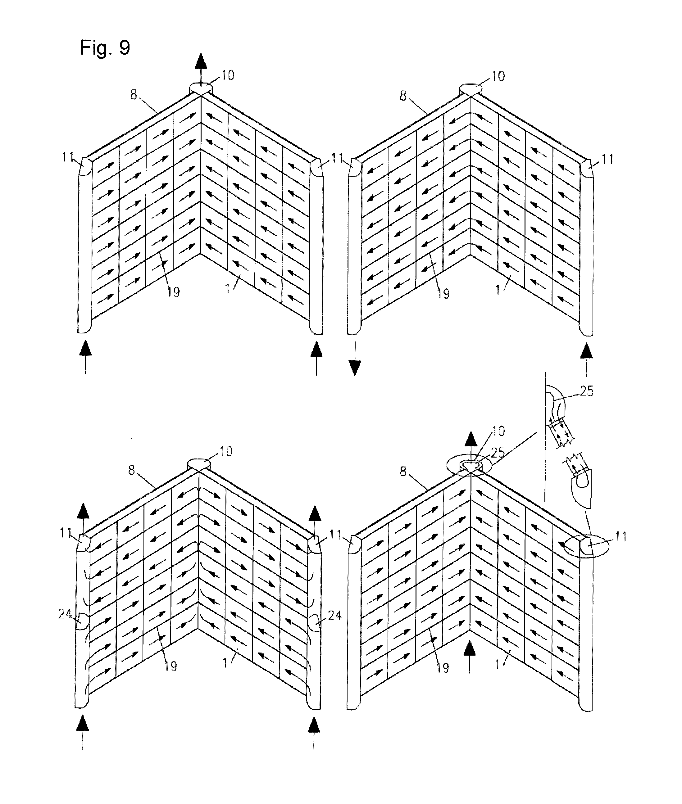
[0034] FIG. 9 shows exemplary connection options of the cooling panels 19, and
[0035] FIG. 10 shows implementations of the tube bundle sheet connections applying, respectively, rubber plates 26, and a combination of rubber plates 26 and O-rings 17.
MODES FOR CARRYING OUT THE INVENTION
[0036] The solution according to the invention provides an alternative of the prior art solutions (see FIGS. 4, 5, 6, 7, 9) by arranging the cooling columns 1 and thereby the cooling tubes 2 horizontally, or substantially horizontally, while keeping the advantageous vertical arrangement of the cooling delta. The ends of tubes are passed through bores arranged on the vertical support columns of the--otherwise necessarily applied--delta structure, and are introduced into inlet and outlet chambers 4, or, without applying these, directly into the inside support column 10 or outside support column 11. In these solutions multiple horizontal cooling columns 7, stacked above one another, constitute a cooling panel 19. In the former case, the chambers 4, 5 may be arranged at the other side (not shown) of the support columns, while in the latter case they are formed integrated in the support columns 10, 11. In this latter case the bores receiving the cooling tubes are disposed on the support columns 10, 11 themselves (see 14, FIG. 8), and the support columns are implemented as enclosed structures. This arrangement provides that the water flows through an enclosed space into and out of the cooling tubes 2 of the heat exchanger bundles 1.
[0037] While in conventional cooling deltas the length of the cooling tubes reaches 25-30 m, in the cooling delta according to the invention the tubes may be much shorter. The reduced tube length involves reducing the flow speed of water in the heat exchanger tubes, with the water side resistance also decreasing according to the third power. The horizontal width of the heat exchanger bundles built into conventional cooling deltas is 2.5-2.7 m. The bundles of the cooling delta according to the invention may exceed that by a factor of 3 to 5.
[0038] The combination of these features allow that the 600-700 MW power limit for single-tower dry cooling systems applied for conventional power stations may be raised to 1200-1600 MW, also allowing the application of the single-tower system for 800-1200 MW PWR or BWR nuclear power station blocks.
[0039] The inventive solution has further important advantages, namely that it reduces the sensitivity to wind and the danger of freezing damage that conventional cooling towers having vertically arranged tubes are subjected to. This may be understood contemplating FIG. 6.
[0040] On a top sectional view of the delta, the flow pattern in wind is shown for a cooling delta arranged at the side of the tower. Since in the air flowing around the tower the wind speed increases to twice the speed measurable further from the building structures, according to the Bernoulli equation air pressure drops, which results in a reduced air flow entering into these deltas. However, this reduced air flow enters the air space of the delta at high velocity at an oblique angle, and is distributed unevenly along the width of the cooling columns 7. Thereby, the outside portions 20 (from the perspective of the centre of the tower) of the downwind cooling column 7 receive wind at high speed, while other portions of the column receive wind at low speeds. The outside corner of the cooling column 7 being in leeward is in a vortex 27, with no or slight inflow, while further inside the space of the delta the inflow speed is higher due to the stronger vertices. As a result of that--assuming a vertically arranged tube axis--the tubes situated at the outside portion 20 of the cooling column shown in the right of the drawing may be overcooled, or, in winter, may be damaged by freezing. This is related to the vertical arrangement of the tubes, as the high air flow density affects the entire length of the cooling tubes in question. The same holds for the cooling tubes 2 situated in the inside portion 21 of the left-side cooling column. Conversely, due to the depression, the cooling tubes 2 of the outside portion of the upwind column provide little or no cooling. As a result of the uneven airflow distribution illustrated above, the heat exchanger tubes are prone to freezing damage, and, in addition to that, the cooling power of the cooling tower is also reduced, which poses problems of operation especially in case of winds occurring in the hottest summer period.
[0041] The situation is completely different in the case of the horizontal tube arrangement implemented according to the invention. Referring also to FIG. 6, at the outside portion of the cooling panel 19, consisting of multiple horizontal cooling columns 7 shown in the right of the drawing, freezing damage cannot occur due to the high air flow density because, on the one hand, the water flowing in from the direction of the outside support column 11 is still warm, and, on the other hand, because the high air flow density occurs only at a relatively short section of the cooling tube 2. The more intensive cooling which occurs at the inside portion of the left-side cooling panel 19 also does not pose any danger, because the effect occurs only at a relatively short longitudinal section of the cooling tubes of the horizontal heat exchanger bundle 1 rather than along the full length of the tubes, as is the case with the vertical cooling tube arrangement. On the other hand, because the water cools down to a relatively smaller extent in the vicinity of the outside support column 11 of this particular cooling panel 19, it enters the critical inside portion 21 at a relatively warm. It may also be conceived that in case of the solution according to the invention all cooling tubes 2 situated at a given side of a cooling panel 19 have almost identical cooling effect. The temperature of outlet water is less uneven than in case of the conventional solution applying vertically arranged cooling tubes. As a result of that, on the whole all cooling deltas have better cooling power than in case of the conventional solution, i.e. wind deteriorates cooling power to a lesser extent.
[0042] Since the suggested dimensions and weight of the cooling deltas is several times bigger than that of conventional deltas, and no suitable lifting equipment is available any more after construction is completed, it would not be possible to dismount and remove a completed cooling delta. Therefore, it should be provided for that the heat exchangers built into the deltas may be removed in smaller units. The invention also contains provisions, explained below, addressing this problem.
[0043] The deltas illustrated in FIG. 7 have two cooling panels 19 arranged at an angle relative to each other and facing to each other. Parallelly arranged, horizontally extending cooling columns 7 are arranged in the cooling panels 19. The cooling columns 7 consist of one or more heat exchanger bundle 1 or bundles connected to each other (the attachments are not shown in themselves). The heat exchanger bundle 1 is the smallest heat exchanger assembly unit of the cooling column 7, i.e. the smallest unit to which the column may be disassembled without cutting. The cooling columns 7, consisting of one or more interconnected heat exchanger bundle 1 or bundles 1, can be integrally removed from the delta. The cooling column has the same width as the cooling components, and its width cannot be further reduced without cutting. The cooling columns 7 are manufactured by joining at least one end of each cooling tube 2 to a tube bundle sheet (or tubesheet) made from continuous plates applying rolling, welding, or any other technology that produces permanent joints. The major constituent parts of the steel structure 8 adapted for supporting the cooling delta are the three--vertical or substantially vertical--inside 10 and outside support columns 11 situated in the three corners of the delta. The surfaces of the support columns facing the cooling columns are machined flat to form flat walls 14, and are configured to comprise bores arranged in a pattern corresponding to the arrangement of the cooling tubes 2 in the heat exchanger bundle 1. The flat wall 14 constitutes either a flat surface or the tube bundle sheet itself through which the media flows to and from the cooling tubes 2. A plurality of cooling columns 7 are connected to each support column pair made up of an inside support column 10 and an outside support column 11. The bored flat walls 14 of the corresponding inside support columns 10 and outside support columns 11 are arranged parallel with each other. The steel structure 8 of the delta, and thereby the inside and outside support columns 10, 11, are fixedly secured. This constraint has to be borne in mind when producing the cooling columns 7 so as to allow them to be removed from between the inside and outside support columns 10, 11.
[0044] A possible embodiment of the invention is presented as follows. A solution extensively applied in conjunction with dry cooling towers is sealing the ends of the cooling tubes 2 by means of rubber rings 17. Such a solution is shown in FIG. 8, in the groove extending between the loose tube bundle sheet 13, the flat wall 14, and the cooling tube 2. The primary advantage of this solution is that the costly welding-in process of the cooling tubes 2 may be omitted. Another advantage is that it is capable of simultaneously sealing the gaps between the cooling tube 2 and the loose tube bundle sheet 13 and between the loose tube bundle sheet 13 and the flat wall 14 (in this case, the support column wall). This sealing solution also allows--and it has not been applied so far--that the loose tube bundle sheet 13 situated at the end portion of the heat exchanger may be inserted in place loosely, without rolling. This allows that a fully installed cooling column may be pulled out from the flat wall 14, i.e. in the present case from the bores of the flat wall 14 formed integrally with the support column 18, in a direction parallel with the tube axis. All that has to be done is to loosen the tube bundle sheet screws 16 joining the tube bundle sheets.
[0045] This, however, would not be sufficient to provide for the removability of the cooling columns if axial displacement were not allowed at the other side of the column (shown in the right side in FIG. 8). To allow the cooling columns to be removed, the following solution may be applied. It is obvious that the cooling tubes 2 of the cooling blocks of the heat exchanger should be arrested in the longitudinal direction in at least one plane perpendicular to the tubes. To achieve that, it is imperative that the cooling tubes 2 are rolled or welded into a fixed tube bundle sheet 12 on at least one side. One end of the cooling column 7 is therefore configured accordingly. The axial displaceability of the cooling tubes 2 is provided for by extending the end of the cooling tubes 2 over the tube bundle sheet to the required extent. Since the cooling column 7 must be fixed in the axial direction, for which the rubber rings are not sufficient, a fixed connection must be provided between the fixed tube bundle sheet 12, disposed at this end of the cooling column 7 and adapted to fixedly engage the tubes, and the flat wall 14 formed on the support column. In addition to that, it should also be provided that, in case this fixed connection is loosened, the free tube ends of the cooling column 7 may be slid into the inside support column 10 through the bores thereof adapted for receiving the cooling tubes 2. This is achieved by applying the following solution:
[0046] A loose tube bundle sheet 13, adapted for receiving in a non-fixed manner the cooling tube ends extending over the fixed tube bundle sheet 12, is placed on the tube ends of the cooling column. Rubber rings 17 are placed on the distal side of the loose tube bundle sheet, on the ends of the cooling tubes 2. In the assembled state, the rubber rings 17 situated between the loose tube bundle sheet 13 and the flat wall 14 functioning as the sealing surface of the inside support column 10 are constricted by inserting such transition pieces 15 between the fixed tube bundle sheet 12 and the loose tube bundle sheet 13 that are resilient, but fixed enough to transfer a pressure force to the loose tube bundle sheet 13 that is sufficient to provide the required sealing effect by deforming the rubber rings 17. In case this transition piece 15 is removed, and the fixed tube bundle sheet 12 is pressed against the flat wall 14 functioning as the sealing surface of the inside support column 10 by tightening the tube bundle sheet screws 16, the cooling column 7 may be longitudinally displaced towards the inside of the inside support column 10 by an extent corresponding to the thickness of the transition piece 15. To achieve that, all that has to be done is to loosen the screws 23 of the loose tube bundle sheet 22 situated at the opposite side. The thickness of the transition piece 15 is chosen such that on the other side the ends of the cooling tubes 2 may come out from bores of the outside support column 11. After that, provided that the tube bundle sheet screws 16, 23 are removed at both sides, the cooling column 7 may be removed by first lifting it at the--now freed up--side facing the outside support column 11, and then pulling and lifting it out at the side facing the inside support column 10. To allow for that, the spatial steel structure of the delta (not shown) is configured such that the side through which the damaged cooling columns 7 are to be removed is free, or arranged to be able to be freed up.
[0047] A major advantage of this solution should be mentioned here, i.e. that this sealing and tube bundle sheet attachment method does not require high manufacturing accuracy. It is not important that the flat walls 14 of the inside and outside support columns 10, 11, being adapted for sealing, fall perfectly in the same plane. It is also not a problem if the sealing flat walls 14 of the respective inside and outside support columns 10, 11 facing each other are not perfectly parallel, and there can even be an angle allowance in their perpendicular angle relative to the cooling tubes 2. There can also be difference in the distances between the sealing flat walls 14 of the inside and outside support columns 10, 11. What is important is the positional accuracy of the bores disposed on the cooling columns, and the bores of the tube bundle sheets 12, 13, 14, but this requirement is not different from requirements set for conventional heat exchangers.
[0048] The connections between the cooling tubes 2 and the inside and outside support columns 10, 11 may be implemented as welded connections. In that case, the components designated by reference numerals 12, 13, 15, 16, 17, 22, 23 in FIG. 8 may be omitted. Damaged cooling tubes 2 may only be repaired in this case by destructively dismantling those surfaces of the corresponding inside and outside support columns 10, 11 that are situated facing the axes of the cooling tubes 2. At the end the repair operation, the dismantled support column must be reconstructed. This may be carried out by closing the previously cut out opening by welding.
[0049] Another possible embodiment of the invention is illustrated in the top drawing of FIG. 10. In this embodiment, the fixed tube bundle sheets 12 of the cooling column 7 are connected at both ends of the cooling column 7 to the machined flat walls 14 of the inside and outside support columns 10, 11 by means of a respective sealing rubber plate 26.
[0050] The above described solution may also be realised (see the drawing at the bottom of FIG. 10) by for instance applying the latter rubber plate solution at the left-side connection, and the arrangement including rubber rings 17 shown in the right in FIG. 8 at the right-side connection. The cooling column may be dismantled from the structure also in this case.
[0051] The circuit connection options of the heat exchangers implemented according to the invention are not different from those of conventional heat exchangers; full cross-flow being the simplest to implement. In this case, the medium to be cooled flows in the same direction in all of the tubes of a given cooling column. According to the examples illustrated in FIGS. 4, 5, 6 the cooling water inlet is at the outside support column 11 of the deltas, while the cooled down water is let out at the inside support column 10. A reversed solution may also be possible, but, as it was shown in the above discussion on the danger of freezing damage, the former solution is more advantageous.
[0052] Further connection options may also be carried out, some of these embodiments being shown in FIG. 9. The top left drawing of the figure illustrates the connection scheme of the embodiment described in relation to FIG. 7.
[0053] An alternative arrangement is also possible (top right drawing, FIG. 9) wherein for instance only the flow direction of the cooling water is changed at the inside support column 10, and the inlet and outlet are disposed on the two outside columns. In this case, each two adjoining cooling columns are connected serially on the water side.
[0054] In a further possible solution (bottom left drawing) that one of the support columns is divided in two by a divider member 24 along a plane perpendicular to the longitudinal axis of the column, while the opposite column is left undivided. Thereby, two flow paths may be configured along the column's axis by installing inlet and outlet stubs on only the divided columns but not on the opposite ones, which latter columns therefore become adapted for only reversing the flow direction of the media. By including multiple vertical divisions, more than two flow paths may also be formed.
[0055] Applying a longitudinal division 25 to the inside support columns 10 in a direction parallel with their axis, a cross-counter-flow connection of the cooling columns may also be realised, as it is shown in the bottom right drawing in FIG. 9. In this solution, the outside support columns 11 may function as the common return chamber of the cross-counter-flow cooling panel 19 having separate inlets through the two inside support columns. Of course, a similar solution may be provided by implementing the double water conduction in the outside support column 11. This may also be realised by arranging the water inlets and outlets exclusively at the bottom of the structure.
[0056] A solution for filling and draining the cooling deltas should also be found which provides that air can flow out from the cooling tubes during filling and water can flow out therefrom during draining. This may be achieved by raising to a small extent the axis of the cooling tubes 2 (seen from the direction of the inlet support column). The same effect may be obtained for instance by disposing the bores of the inside support column 10 a few centimeters higher, which is allowed by the resilient sealing method described above. According to this solution, the draining ports of the cooling delta are disposed at the bottommost portion of the inlet support columns.
[0057] Such an arrangement is also possible wherein the cooling tubes 2 descend towards the direction of oufflowing air (taking into account the filling direction). In this case, the draining means is disposed at the bottommost portion of the outlet support column. In such an embodiment, the hydraulic resistance of the cooling tube 2 must exceed the hydrostatic pressure difference caused by the height difference resulting from the tube's inclination.
[0058] In case of this example, the media enters the outside support column 11 at the bottom, and is let out at the top of the inside support column 10. The deltas are filled also in this direction, such that air is let out at the top portion of the inside support column 10. Draining may be carried out in the opposite direction.
[0059] The invention is, of course, not limited to the preferred embodiments described in details above, but further variants, modifications and developments are possible within the scope of protection determined by the claims.
* * * * *
D00000
D00001
D00002
D00003
D00004
D00005
D00006
D00007
XML
uspto.report is an independent third-party trademark research tool that is not affiliated, endorsed, or sponsored by the United States Patent and Trademark Office (USPTO) or any other governmental organization. The information provided by uspto.report is based on publicly available data at the time of writing and is intended for informational purposes only.
While we strive to provide accurate and up-to-date information, we do not guarantee the accuracy, completeness, reliability, or suitability of the information displayed on this site. The use of this site is at your own risk. Any reliance you place on such information is therefore strictly at your own risk.
All official trademark data, including owner information, should be verified by visiting the official USPTO website at www.uspto.gov. This site is not intended to replace professional legal advice and should not be used as a substitute for consulting with a legal professional who is knowledgeable about trademark law.