Passive Pump Filter
LEE; JOSEPH B.
U.S. patent application number 13/546736 was filed with the patent office on 2015-12-31 for passive pump filter. The applicant listed for this patent is JOSEPH B. LEE. Invention is credited to JOSEPH B. LEE.
| Application Number | 20150377511 13/546736 |
| Document ID | / |
| Family ID | 54930090 |
| Filed Date | 2015-12-31 |
| United States Patent Application | 20150377511 |
| Kind Code | A1 |
| LEE; JOSEPH B. | December 31, 2015 |
PASSIVE PUMP FILTER
Abstract
A portable forced air heating unit provided with a filter cover. The filter cover reduces the dust and particulates that may enter the air intake filter of an air compressor or unit. The filter cover deflects particulates carried by the forced air. The filter cover may extend from the air compressor.
| Inventors: | LEE; JOSEPH B.; (Bowling Green, KY) | ||||||||||
| Applicant: |
|
||||||||||
|---|---|---|---|---|---|---|---|---|---|---|---|
| Family ID: | 54930090 | ||||||||||
| Appl. No.: | 13/546736 | ||||||||||
| Filed: | July 11, 2012 |
| Current U.S. Class: | 432/92 ; 126/110R; 126/99D; 432/222 |
| Current CPC Class: | F24H 9/1881 20130101; F24H 3/0488 20130101; F24H 9/2085 20130101; Y02B 30/00 20130101; Y02B 30/28 20130101 |
| International Class: | F24H 3/04 20060101 F24H003/04; F24H 9/20 20060101 F24H009/20; F24H 9/00 20060101 F24H009/00 |
Claims
1. A portable forced air heating unit comprising: an outer housing having an inlet end and an outlet end; an air compressor, a motor, and a fan positioned within said outer housing, wherein said air compressor includes a filter opening defined by an upstream end surface, said filter opening having an air intake filter therein; wherein said fan forces air in a longitudinal first direction from said inlet end to said outlet end; a filter cover having an end plate with a longitudinal flange and skirt, wherein said end plate is semicircular in shape with an outer periphery having an curved edge connected by a straight edge, and said flange projects from said curved edge and said skirt projects from said straight edge, said flange and skirt circumscribing an outer periphery of said filter opening, wherein said skirt extends between said air compressor end surface and said end plate thereby said end plate is longitudinally spaced upstream from said air compressor end surface and radially disposed beyond said filter opening outer periphery creating a longitudinal gap radially across said air intake filter; wherein said longitudinal flange of said filter cover extends longitudinally from said end plate in said longitudinal first direction and is radially spaced from an outer wall of said air compressor by said skirt towards said outer housing creating a radial gap, and a free end of said longitudinal flange, said skirt, and a cylindrical outer wall of said air compressor defines an inlet opening, said inlet opening in fluid communication with said air intake filter through said radial gap and said longitudinal gap, wherein said inlet opening faces substantially towards said outlet end of said outer housing thereby allowing air to enter said inlet opening in a longitudinal second direction, wherein said longitudinal second direction is opposite to said longitudinal first direction.
2. (canceled)
3. (canceled)
4. The portable forced air heating unit of claim 1 wherein said inlet opening is circumferential in shape.
5. The portable forced air heating unit of claim 1 wherein inlet opening is longitudinally positioned downstream of said filter opening of said air compressor.
6. The portable forced air heating unit of claim 1 further including one or more tabs spacing said end plate from said end surface of said air compressor.
7. A portable heater comprising: an outer housing having an inlet end and an outlet end; an air compressor, a motor, and a fan positioned within said outer housing, wherein said air compressor includes a cylindrical outer wall longitudinally extending from an upstream end surface, wherein said end surface includes a filter opening defined by an outer periphery, said filter opening is in fluid communication with an air intake filter; wherein said fan forces air in a longitudinal first direction from said inlet end to said outlet end; a filter cover having an end plate with a longitudinally extending flange and skirt, wherein said endplate is spaced upstream from said filter opening and wherein said flange and said skirt circumferential surrounds said outer periphery of said filter opening to define a longitudinal gap between said end surface of said compressor and said end plate of said filter cover, wherein said longitudinal gap further extends radially across said air intake filter between said flange and said skirt; wherein said flange of said filter cover extends longitudinally from said end plate in said longitudinal first direction and is radially spaced from said outer wall of said air compressor towards said outer housing creating a radial gap in fluid communication with said longitudinal gap; said flange, said skirt, and said cylindrical outer wall of said air compressor defining an inlet opening, wherein said inlet opening is circumferentially discontinuous about said cylindrical outer wall of said air compressor, said inlet opening is in fluid communication with said air intake filter through said radial gap and said longitudinal gap; and wherein said filter cover is positioned upstream from said filter opening to deflect particulates from longitudinal entering said air intake filter in said longitudinal first direction.
8. The portable heater of claim 7 wherein said filter cover is longitudinally aligned with said filter opening and larger than said outer periphery of said filter opening.
9. The portable heater of claim 7 wherein said endplate is substantially perpendicular to said longitudinal first direction.
10. The portable heater of claim 9 wherein said flange extends from said endplate upstream from said filter opening to a position downstream from said filter opening.
11. The portable heater of claim 7 wherein said filter cover extends from a first longitudinal position upstream from said filter opening to a second longitudinal position downstream from said filter opening.
12. The portable heater of claim 7 wherein said filter cover projects from said air compressor.
13. The portable heater of claim 7 wherein said filter cover defines a first directional flow of air into said air intake filter in a longitudinal second direction, wherein said longitudinal second direction is opposite to said longitudinal first direction.
14. The portable heater of claim 13 wherein said filter cover defines a second directional flow of air into said air intake filter, wherein said second directional flow of air flows in a radial direction that is substantially perpendicular to said longitudinal second direction.
15. A portable forced air heating unit comprising: an outer housing having an inlet end and an outlet end; an air compressor, a motor, a fan, and a filter cover positioned within said outer housing, wherein said air compressor includes a cylindrical outer wall longitudinally extending from an upstream end surface, wherein said air compressor includes an upstream facing filter opening in said upstream end surface, said filter opening includes an air intake filter therein; wherein said fan forces air in a longitudinal first direction from said inlet end to said outlet end; a filter cover defines an inlet opening longitudinally positioned downstream of a filter opening of said air compressor, wherein said inlet opening is circumferentially discontinuous about said cylindrical outer wall of said air compressor, said inlet opening receives a first directional flow of air into said air intake filter, wherein said first directional flow of air is in a longitudinal second direction substantially opposite to said longitudinal first direction of forced air; and wherein said filter cover defines a second directional flow of air, wherein said second directional flow of air flows in a radial direction that is substantially perpendicular to said longitudinal second direction.
16. (canceled)
17. The portable forced air heating unit of claim 15 wherein said filter cover includes an endplate and a longitudinally extending flange.
18. The portable forced air heating unit of claim 15 wherein said filter cover and said air compressor combine to define at least said first directional flow of air into said air intake filter.
19. (canceled)
20. The portable forced air heating unit of claim 15 wherein said inlet opening faces downstream in said longitudinal first direction.
21. A portable forced air heating unit comprising: a housing having an inlet end and an outlet end; an air compressor, a motor, a fan, and a filter cover positioned within said housing, wherein said air compressor includes an upstream facing filter opening in said upstream end surface, said filter opening includes an air intake filter therein; wherein said fan forces air in a longitudinal first direction from said inlet end to said outlet end; a filter cover defining a longitudinal air channel, wherein said longitudinal air channel allows a first directional flow of air to be in upstream fluid communication with said air intake filter of said air compressor, wherein said first directional flow of air travels in a longitudinal second direction substantially opposite to said longitudinal first direction of forced air; and wherein said filter cover deflects air particulates within forced air in said longitudinal first direction from entering said longitudinal air channel in said substantially opposite said longitudinal second direction.
22. The portable forced air heating unit of claim 21 further comprising a radial air channel in fluid communication between said air intake filter and said longitudinal air channel.
Description
TECHNICAL FIELD
[0001] The present invention relates to heaters in particular to a portable forced air heating unit with a filter.
BACKGROUND OF THE INVENTION
[0002] Portable heating units may be used in a variety of environments as desired by the user. However, in dusty environments, such as but not limited to construction (ex: drywall) and agricultural applications, the level of ambient particulates can be substantial, quickly clogging an exposed pump air intake filter. Frequent cleaning or replacement of this air intake filter is common in these environments. Undesirable buildup of particles upon the air intake filter may lead to malfunction of the air compressor, motor pump assembly, or heater. As such, there is a need to effectively separate or reduce dust and particulates from the portable heating unit's forced air from entering the pump air intake filter or heater filter.
BRIEF DESCRIPTION OF THE DRAWINGS
[0003] In the drawings, like reference characters generally referred to the same parts throughout the different views. Also, the drawings are not necessarily to scale, emphasis instead generally being placed upon illustrating the principals of the invention.
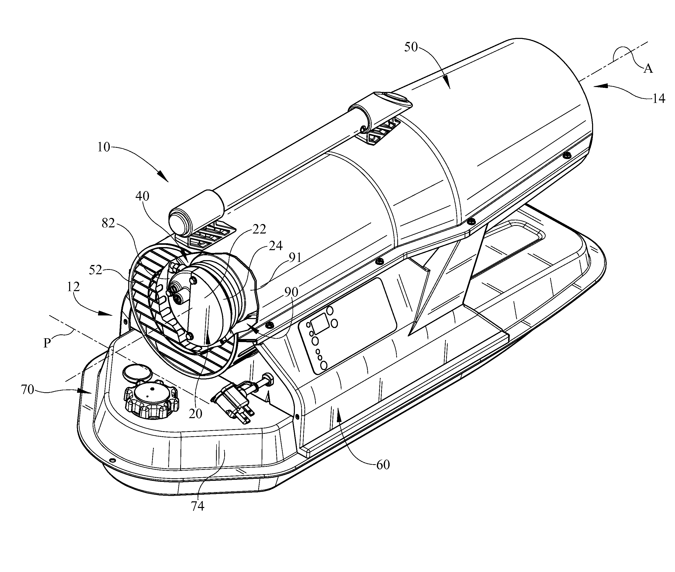
[0004] FIG. 1 is a perspective view of a portable forced air heating unit according to one embodiment with portions of the housing broken away illustrating the filter cover;
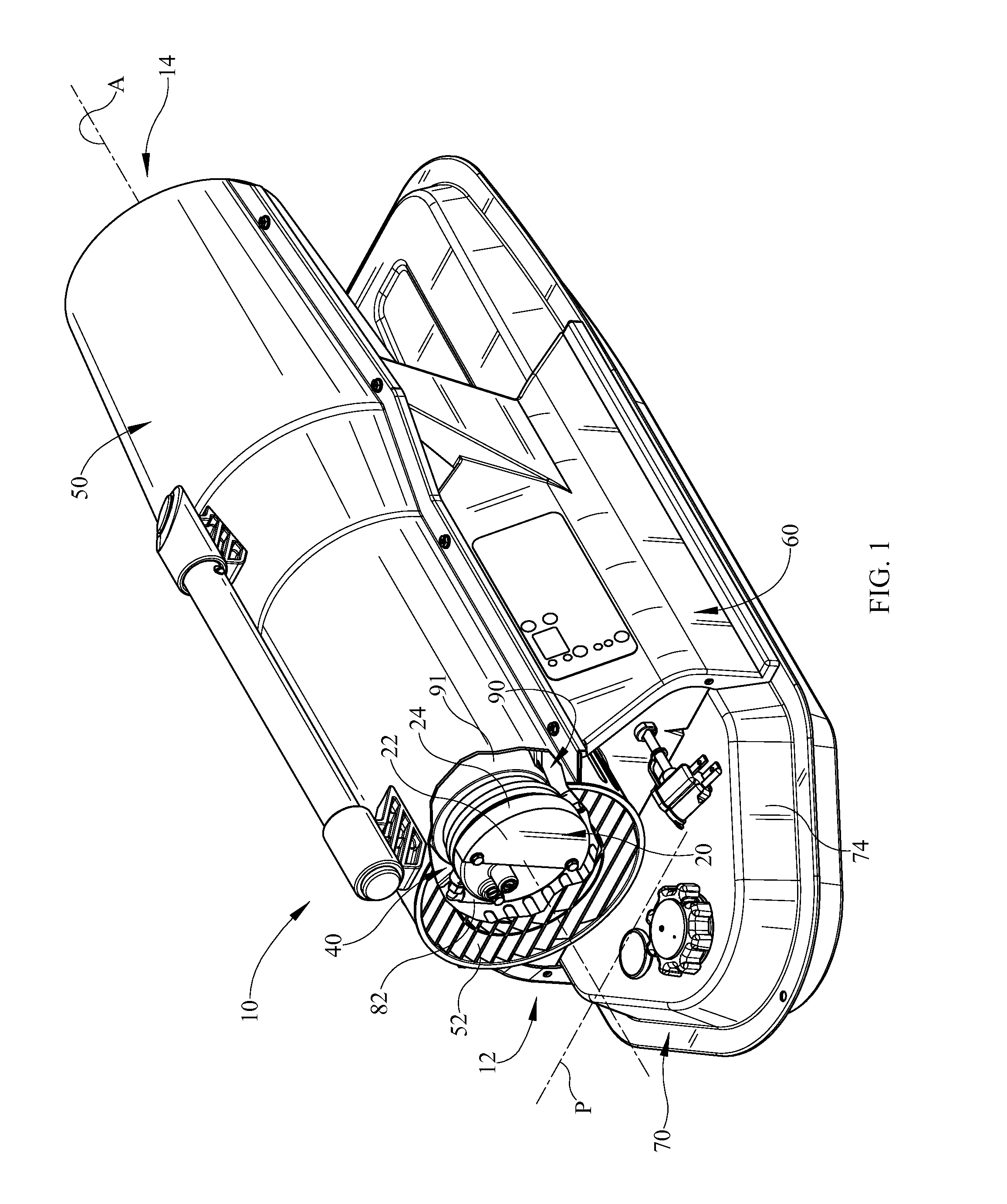
[0005] FIG. 2 is a perspective view of the filter cover exploded from the air compressor and motor of FIG. 1 with portions of the heating unit broken away;
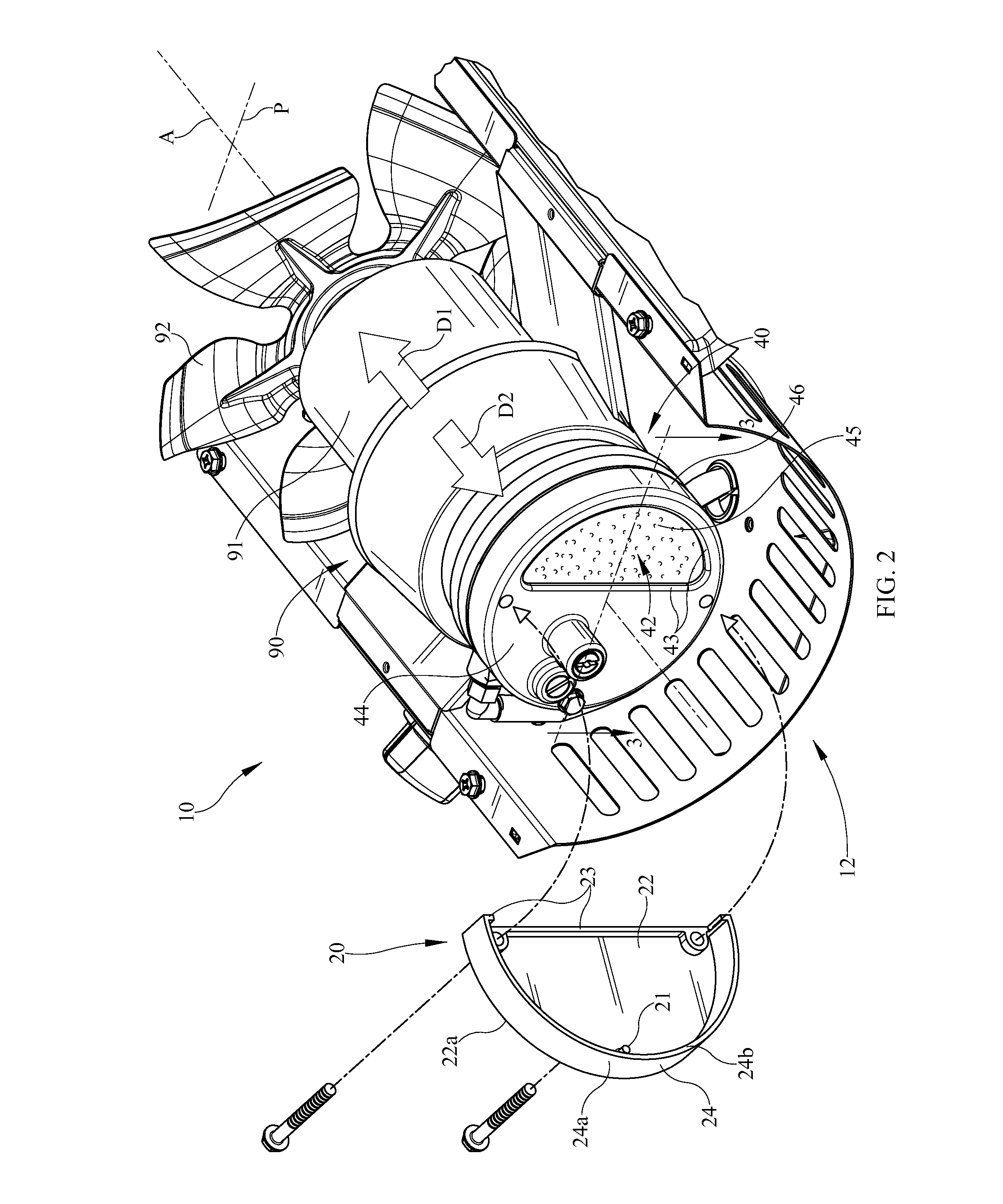
[0006] FIG. 3 is a sectional, perspective view of the filter cover engaged with the air compressor of the heating unit of FIG. 2 taken along line 3-3 with portions of the heating unit broken away;
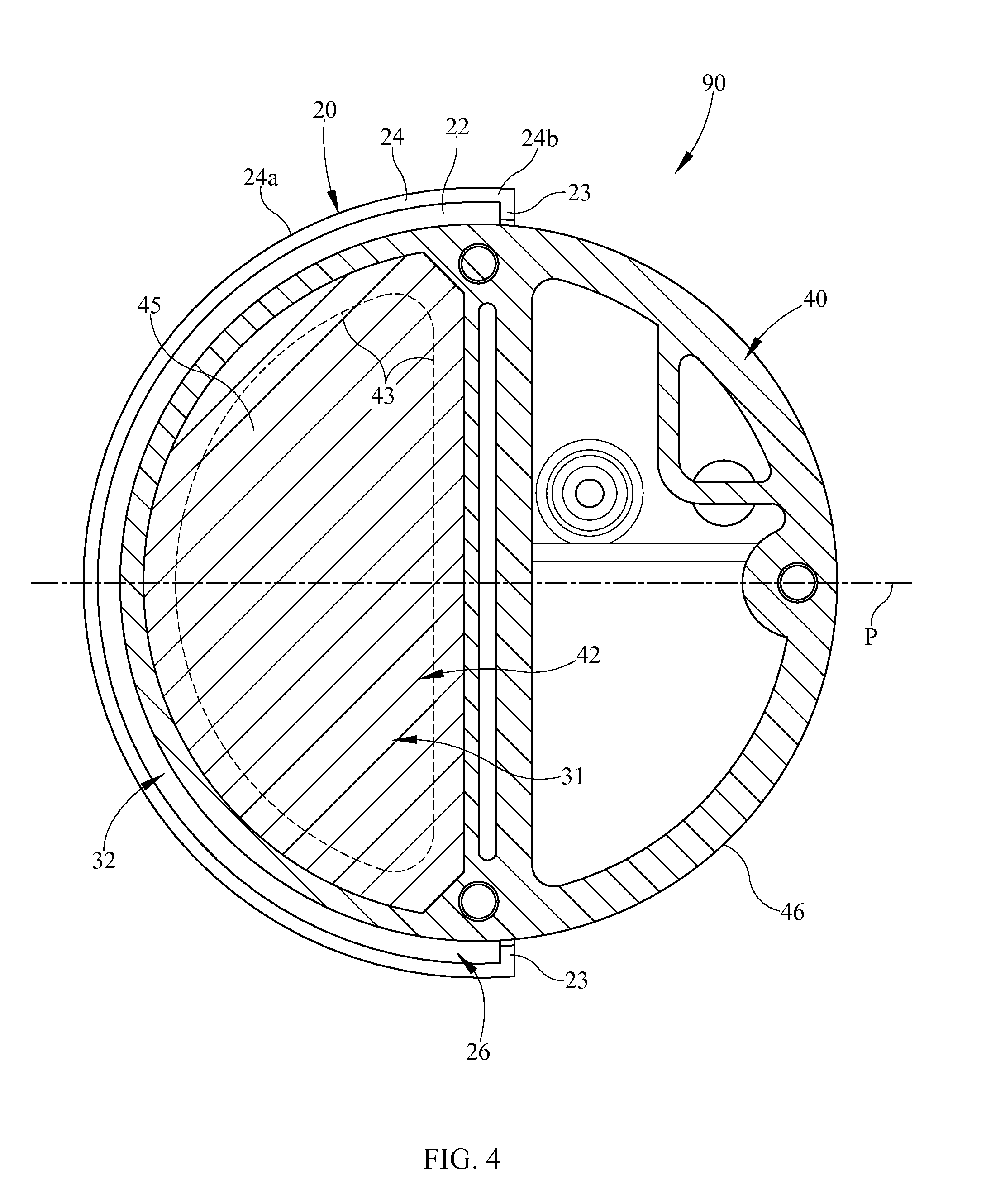
[0007] FIG. 4 is a sectional view of the filter cover and air compressor of FIG. 3 taken along 4-4 with the air intake filter removed; and
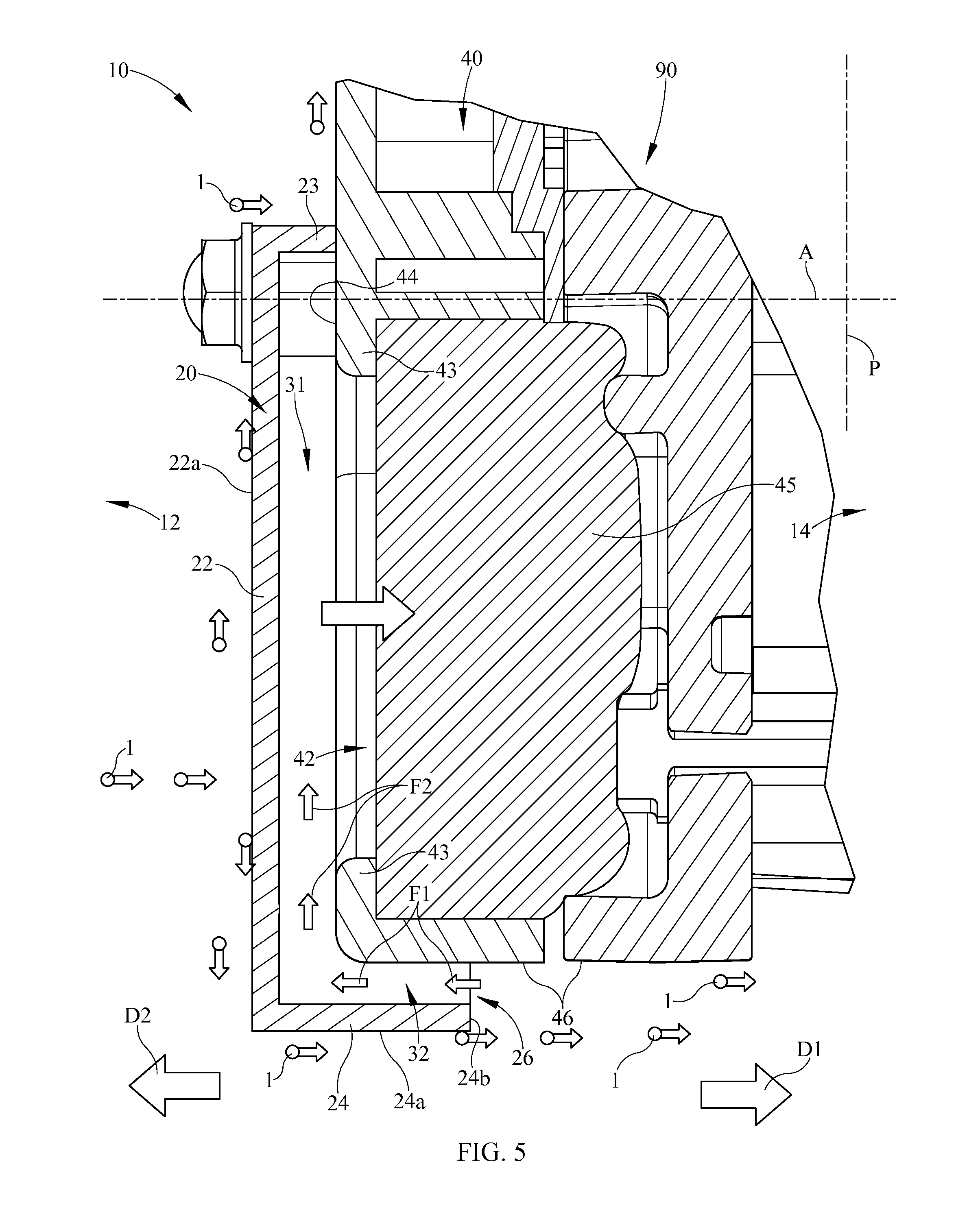
[0008] FIG. 5 is an enlarged sectional view of the heating unit of FIG. 2 taken along line 3-3 with portions of the heating unit broken away and the filter cover tab removed.
DETAILED DESCRIPTION
[0009] It is to be understood that the invention is not limited in its application to the details of construction and the arrangement of components set forth in the following description or illustrated in the drawings. The invention is capable of other embodiments and of being practiced or of being carried out in various ways. Also, it is to be understood that the phraseology and terminology used herein is for the purpose of description and should not be regarded as limiting. The use of "including," "comprising," or "having" and variations thereof herein is meant to encompass the items listed thereafter and equivalents thereof as well as additional items. Unless limited otherwise, the terms "connected," "coupled," "in communication with" and "mounted," and variations thereof herein are used broadly and encompass direct and indirect connections, couplings, and mountings. In addition, the terms "connected" and "coupled" and variations thereof are not restricted to physical or mechanical connections or couplings.
[0010] Furthermore, and as described in subsequent paragraphs, the specific mechanical configurations illustrated in the drawings are intended to exemplify embodiments of the invention and that other alternative mechanical configurations are possible.
[0011] The portable forced air heating unit 10 depicted in the drawings provides for a filter cover or baffle 20 that effectively deflects particulates from entering an air intake filter 45 of the heating unit 10. Filter cover 20 may be made from a variety of material not limited to plastic, metal, or combinations thereof. The particles may be a variety of undesirable dust, materials, or liquid that may be forced through the heater during operational use in different environments such as, but not limited to, construction and agricultural environments.
[0012] Kerosene forced air heaters conventionally include a housing, a burner head assembly mounted within the housing, and an air blower system within the housing behind the burner head assembly. Fuel (kerosene, fuel oil, or diesel fuel, etc.) is conveyed to the burner head assembly and combustion chamber assembly. The blower supplies combustion air to the burner head assembly and forces hot combustion gases from the burner head assembly while cooling the exterior of the burner head assembly and combustion chamber assembly. Although a kerosene forced air heater is shown in detail it is understood that the embodiments of the invention may be used in any type of portable forced air heater such as, but not limited to, a gas or multi-fuel forced air heater.
[0013] As shown in FIGS. 1-5, there is one embodiment of a portable forced air heating unit 10 within which a filter cover 20 is utilized. Unit 10 includes a fuel tank assembly 70, an elongated housing 50 superposed upon the fuel tank assembly 70, and a controls compartment 60 disposed between so as to join the housing 50 to fuel tank assembly 70. Housing 50 includes a combustion chamber assembly (not shown), described herein, within which a mixture of fuel and air is burned, and the fuel tank assembly 70 contains a reservoir or tank 74 of fuel for burning within the combustion chamber assembly. Routed through controls compartment 60 between fuel tank assembly 70 and housing 50 is a fuel line (not shown) and air line 82 and appropriate controls whose structure and function are well-known in the art are associated with the housing 50 and fuel tank assembly 70 for controlling the heater operation. It should also be understood that the controls compartment 60 may be located or mounted in any number of positions and be a variety of dimensions, shapes, quantities, and construction. Further, additional components may be included in the unit such as the type shown in U.S. application Ser. No. 12/186,110 filed Aug. 5, 2008 and entitled LOW PRESSURE FORCED AIR HEATER, which is herein incorporated by reference.
[0014] Housing 50 is generally cylindrical and supports a combustion chamber assembly. Housing 50 and/or combustion chamber assembly may be a variety of different shapes, sizes, configurations, constructions, and still be within the scope of the embodiments. Combustion chamber assembly includes a cylindrical outer shell or heat shield and a cylindrical inner shell or combustion chamber therewithin. Combustion chamber is arranged substantially centrally of heat shield so that an annular spacing exists between combustion chamber and heat shield. One end or inlet end of the combustion chamber is covered by a burner head assembly (not shown), and the opposing end or outlet end of combustion chamber 44 may be covered by an afterburner. Combustion chamber assembly is supported within housing 50 by, for example, brackets joined between housing 50 and heat shield.
[0015] During operation of heating unit 10, air is drawn from the surrounding environment through inlet end 12 of housing 50, heated, and then forced in the downstream or longitudinal first direction D1 along the longitudinal axis A and out of outlet end 14 to heat the surrounding environment. Housing 50 may include one or more louvers 52 at inlet end 12. Burner head assembly includes an air line 82 in fluid communication with the motor and pump assembly 90. Motor 91 drives a fan 92 to draw air from the back of the unit or inlet end 12 in order to circulate or push air into and around a combustion chamber assembly. Motor 91 may also drive the pump or air compressor 40. Air may be circulated through a rear plate when entering combustion chamber assembly. A mixture of fuel and air is routed into the combustion chamber through burner head assembly where it is burned in a combustion process. The fuel may be delivered to the combustion chamber through fuel line in the form of oil droplets formed by an atomizing process. Regardless of the atomizing process, however, incomplete combustion may occur within the combustion chamber due to non-uniformity in size of the fuel droplets or an uneven mixing of the fuel droplets with air. Combustion chamber outlet end provides the discharge end for combustion chamber, and the afterburner is positioned adjacent the outlet end of the chamber for burning fuel particles which are not burned within the combustion chamber to reduce the likelihood that unburned fuel particles will be discharged from heater 10 and enter the surrounding environment. The air is heated and provides a stream of clean, hot air out of the exit or outlet end 14 of unit 10. Air circulated between the combustion chamber assembly and housing 50 cools the burner head assembly, combustion chamber assembly, and housing 50.
[0016] As shown in FIGS. 1-5, air compressor 40 may be of a variety of compressor types and sizes so long as it is capable of compressing a quantity of air appropriate for the particular force air heating unit 10 to a pressure that is also appropriate for the particular unit in which it is installed. In some embodiments, air compressor 40 is of the carbon vane type. Air compressor 40 includes a filter opening 42 defined by an outer periphery edge or rim 43 of the air compressor end surface 44 allowing air to enter the air intake filter 45. One embodiment of the filter opening 42 is shown as positioned on the axial end surface 44 of the air compressor 40 facing in the upstream or longitudinal second direction D2, thereby the longitudinal forced air in the opposing longitudinal first direction D1 could directly enter the filter 45 without the use of the filter cover 20. As such, filter cover 20 in operation (FIG. 5) deflects this longitudinal forced air, and its carried particulates 1, away from the filter 45 or filter opening 42. The filter cover 20 redirects the longitudinal air flow before entering the filter 45 through a serpentine or multi-directional flow or another direction, as described in more detail below, to deflect away from the filter opening 42 or filter 45. This passive filtration of dust particles or particulates 1 therefore occurs without the use of additional filtering media. It is understood that a variety of filtering media, such as but not limited to open cell foam, could also be used in combination with the filter cover 20 if desired. This advantageously reduces the buildup of particles in the filter 45 as well as reducing such particles from entering the carbon vane pump.
[0017] Although filter cover 20 is shown in detail in the drawings, it merely represents one embodiment, and it is to be understood that there are a variety of shapes, dimensions, quantities, positions within the unit, compositions, and constructions which may be used and still be within the scope of these embodiments to deflect airborne particles from entering the air intake filter 45. It should be understood, that a variety of filter cover embodiments may be used with a variety of air compressor, filter, and filter opening embodiments.
[0018] As shown in FIGS. 1-5, filter cover 20 is positioned within the forced air longitudinal flow along longitudinal axis A of the housing 50 between the inlet end 12 and the outlet end 14. In one embodiment, filter cover 20 is releasably secured or fixed to air compressor 40. In other embodiments the filter cover 20 may be integral with the air compressor 40, mounted to other structure of the heating unit 10, or combination thereof. Filter cover 20 is longitudinally aligned with the air intake filter 45 and may be larger than the filter opening 42 thereby at least partially extending outside the outer peripheral extent of the filter opening 42 or rim 43. Filter cover 20 may include an end plate 22 and a longitudinally extending flange 24. End plate 22 is longitudinally spaced upstream from the end surface 44 of the air compressor 40 thereby creating a longitudinal gap 31 (FIGS. 3 and 5). End plate 22 is shown as being substantially perpendicular to the longitudinal axis A of the unit 10. However it should be understood that the end plate 22 and/or the flange 24 may be of a variety of sizes, shapes, constructions, orientations, and positions with the unit 10. In some embodiments, a projecting skirt 23 from end plate 22 may abut the end surface 44 and circumferentially connect with the flange 24 to define the longitudinal spacing distance creating the longitudinal gap 31. An additional tab 21 may be used between the skirt 23 and flange 24 to abut the end surface 44 to support the end plate's longitudinal spacing from the air compressor 40. The flange 24 is radially and outwardly spaced along the perpendicular axis P from the outer surface 46 of the air compressor 40 thereby creating a radial gap 32 (FIGS. 3-5). The filter cover 20, or more specifically the flange 24, may extend from a first longitudinal position upstream from the filter opening 42 to a second longitudinal position downstream from the filter opening 42. The filet cover 20 may include an inlet opening 26 from which air enters the filter cover 20 and continues to air intake filter 45. Inlet opening 26 may be integral or defined solely by the filter cover 20, but is shown in FIGS. 3-5 as being defined by a combination of the filter cover flange 24 and the outer surface 46 of the air compressor 40. Inlet opening 42 may also be described as being downstream of the filter opening 42 or air compressor end surface 44. Inlet opening 26 faces downstream towards the outlet end 14 and may circumferentially surround at least a portion of the air compressor 40. The orientation of the inlet opening 26 is in a substantially perpendicular plane, along axis P, relative to the longitudinal axis A of the unit 10 (FIG. 4). Although shown as discontinuous or circumferentially surrounding only a portion of the outer diameter of the air compressor 40 (FIG. 4), the inlet opening 26 may extend 360 degrees about the compressor. As such, the inlet opening 26 may be a variety of shapes, positions, orientations relative to the filter cover, sizes, constructions, and quantities and still be within the scope of the embodiments.
[0019] In operation, as best illustrated in FIGS. 5, the filter cover 20 creates a multi-directional or another directional flow of intake air in fluid communication with the air intake filter 45 through inlet opening 26 to deflect airborne particles 1. During operation of the heating unit 10, the longitudinal forced air with particulates 1 enters from inlet end 12 of the heating unit 10 and travels in longitudinal first direction D1 to outlet end 14 of the heating unit 10. The forced or carried particulates 1 contact or deflect around the outer surface 22a of the end plate 22 and generally move outwardly beyond the flange 24. Particulates 1 then may travel along or outside the outer surface 24a of the longitudinal flange 24 until the particulates 1 continue downstream past the inlet opening 26. In this manner, particulates 1 are prevented from entering the inlet opening 26 of the filter cover 20. Therefore, particles 1 pulled into the inlet end 12 and carried by the longitudinal forced air along the longitudinal axis A in the longitudinal first direction D1 have a tendency to continue downstream to the outlet end 14 instead of flowing against the direction of forced air around the free end 24b of the flange 24 and back into the inlet opening 26 or radial gap 32.
[0020] As shown in FIGS. 4 and 5 the inlet opening 26 of the filter cover 20 faces downstream, intake air flow travels at least in an upstream or first directional flow of air F1 upon entering the inlet opening 26, opposite to the forced longitudinal air flow in the longitudinal first direction D1. Subsequently, the intake air flow continues to travel through the radial gap 32 before redirecting in a radially inward direction or second directional flow of air F2, transverse to the longitudinal axis A, into the axial gap 31. The air intake flow continues from the axial gap 31 downstream into the filter opening 42 containing the air intake filter 45.
[0021] Although the air intake flow may travel in one or more directions dissimilar to the longitudinal first direction D1, it merely represents one embodiment, and it is to be understood that there are a variety of constructions, quantities, shapes, sizes, and orientations of the filter cover 20, alone or in combination with the air compressor 40, that may be used and still be within the scope of the embodiments to deflect or redirect air flow into the filter.
[0022] It is understood that while certain embodiments of the invention have been illustrated and described, it is not limited thereto except insofar as such limitations are included in the following claims and allowable functional equivalents thereof.
* * * * *
D00000
D00001
D00002
D00003
D00004
D00005
XML
uspto.report is an independent third-party trademark research tool that is not affiliated, endorsed, or sponsored by the United States Patent and Trademark Office (USPTO) or any other governmental organization. The information provided by uspto.report is based on publicly available data at the time of writing and is intended for informational purposes only.
While we strive to provide accurate and up-to-date information, we do not guarantee the accuracy, completeness, reliability, or suitability of the information displayed on this site. The use of this site is at your own risk. Any reliance you place on such information is therefore strictly at your own risk.
All official trademark data, including owner information, should be verified by visiting the official USPTO website at www.uspto.gov. This site is not intended to replace professional legal advice and should not be used as a substitute for consulting with a legal professional who is knowledgeable about trademark law.