System And Method For Controlling And Diagnosing Passive Storage Devices In Exhaust Aftertreatment Systems
Yezerets; Aleksey ; et al.
U.S. patent application number 14/753698 was filed with the patent office on 2015-12-31 for system and method for controlling and diagnosing passive storage devices in exhaust aftertreatment systems. The applicant listed for this patent is Cummins Inc.. Invention is credited to Neal W. Currier, Michael J. Ruth, Aleksey Yezerets.
| Application Number | 20150377102 14/753698 |
| Document ID | / |
| Family ID | 54929989 |
| Filed Date | 2015-12-31 |

| United States Patent Application | 20150377102 |
| Kind Code | A1 |
| Yezerets; Aleksey ; et al. | December 31, 2015 |
SYSTEM AND METHOD FOR CONTROLLING AND DIAGNOSING PASSIVE STORAGE DEVICES IN EXHAUST AFTERTREATMENT SYSTEMS
Abstract
An internal combustion engine system includes an engine and an aftertreatment system that is connected to the engine to receive exhaust flow from the engine. The aftertreatment system includes a passive storage device for passively storing NO.sub.x and/or hydrocarbons produced by the engine during cold start and low temperature operating conditions, and a NO.sub.x reduction catalyst downstream of the passive storage device for receiving the NO.sub.x released from the passive storage device when temperature conditions in the exhaust flow and/or NO.sub.x reduction catalyst are above an effective temperature for NO.sub.x reduction. Diagnostics of the passive storage device and/or a sensor downstream of the passive storage device are contemplated that are based at least in part on an expected sensor output in response to a storage mode of operation or a release mode of operation of the passive storage device. Furthermore, reductant injection control is provided in response to a NO.sub.x amount released from the passive storage device.
| Inventors: | Yezerets; Aleksey; (Columbus, IN) ; Ruth; Michael J.; (Franklin, IN) ; Currier; Neal W.; (Columbus, IN) | ||||||||||
| Applicant: |
|
||||||||||
|---|---|---|---|---|---|---|---|---|---|---|---|
| Family ID: | 54929989 | ||||||||||
| Appl. No.: | 14/753698 | ||||||||||
| Filed: | June 29, 2015 |
Related U.S. Patent Documents
| Application Number | Filing Date | Patent Number | ||
|---|---|---|---|---|
| 62017892 | Jun 27, 2014 | |||
| Current U.S. Class: | 60/274 |
| Current CPC Class: | F01N 3/2066 20130101; Y02T 10/26 20130101; F01N 3/2033 20130101; F01N 2610/02 20130101; F01N 11/007 20130101; F01N 3/0814 20130101; F01N 3/208 20130101; F01N 3/103 20130101; F01N 2550/03 20130101; F01N 9/00 20130101; F01N 2900/1402 20130101; Y02T 10/24 20130101; Y02T 10/47 20130101; F01N 2610/03 20130101 |
| International Class: | F01N 3/08 20060101 F01N003/08; F01N 3/10 20060101 F01N003/10; F01N 3/20 20060101 F01N003/20; F01N 11/00 20060101 F01N011/00; F01N 9/00 20060101 F01N009/00 |
Claims
1. A method, comprising: operating an internal combustion engine to produce an exhaust flow to an aftertreatment system including at least a passive storage device and a NO.sub.x reduction device downstream of the passive storage device; storing NO.sub.x from the exhaust flow with the passive storage device during a NO.sub.x storage mode of operation that occurs when the exhaust flow is in a low temperature condition; releasing NO.sub.x from the passive storage device in a NO.sub.x release mode of operation when the NO.sub.x reduction device is above an effective reduction temperature threshold for reducing NO.sub.x across the NO.sub.x reduction device; determining a differential between an oxygen amount downstream of the passive storage device and an oxygen amount upstream of the passive storage device; and providing a system output in response to the differential.
2. The method of claim 1, further comprising: determining whether the passive storage device is in the NO.sub.x storage mode of operation or the NO.sub.x release mode of operation; in response to the mode of operation, determining an expected differential between the oxygen amount upstream of the passive storage device and the oxygen amount downstream of the passive storage device; and wherein providing the system output includes diagnosing a fault condition of the passive storage device in response to the determined differential deviating from the expected differential by more than a threshold amount.
3. The method of claim 1, wherein determining the differential includes measuring an oxygen amount downstream of the passive storage device and measuring an oxygen amount upstream of the passive storage device.
4. The method of claim 3, wherein measuring the oxygen amount downstream of the passive storage device includes determining an oxygen component of an output of a NO.sub.x sensor downstream of the passive storage device.
5. The method of claim 4, wherein measuring the oxygen amount upstream of the passive storage device includes measuring the oxygen amount with an oxygen sensor.
6. The method of claim 4, wherein measuring the oxygen amount upstream of the passive storage device includes determining the oxygen amount from one or more operating parameters of the engine.
7. The method of claim 1, wherein determining the differential includes measuring a difference between an oxygen amount downstream of the passive storage device and an oxygen amount upstream of the passive storage device.
8. The method of claim 1, wherein the system output is operating the internal combustion engine to induce one of the NO.sub.x storage mode of operation and the NO.sub.x release mode of operation of the passive storage device.
9. The method of claim 8, further comprising: determining an expected output of a NO.sub.x sensor downstream of the passive storage device in response to the induced mode of operation of the passive storage device; and determining a fault condition of the NO.sub.x sensor in response to a measured output of the NO.sub.x sensor deviating from the expected output by more than a threshold amount.
10. The method of claim 1, wherein the NO.sub.x reduction device is a selective catalytic reduction (SCR) catalyst and the aftertreatment system includes a reductant source operationally to provide an ammonia based reductant upstream of the SCR catalyst and downstream of the passive storage device.
11. The method of claim 1, wherein providing the system output includes at least one of modulating a NO.sub.x output of the engine and modulating a temperature of the exhaust flow in response to the differential.
12. A method, comprising: operating an internal combustion engine to produce an exhaust flow to an aftertreatment system including at least a passive storage device and a NO.sub.x reduction device downstream of the passive storage device; storing hydrocarbons from the exhaust flow with the passive storage device during a hydrocarbon storage mode of operation of the PSD that occurs when the exhaust flow is in a low temperature condition; oxidizing hydrocarbons from the passive storage device in a hydrocarbon release mode of operation of the passive storage device that occurs when the passive storage device is above a light-off temperature; determining a differential between an air-fuel ratio downstream of the passive storage device and an air-fuel ratio upstream of the passive storage device; and providing a system output in response to the differential.
13. The method of claim 12, further comprising: determining whether the passive storage device is in the hydrocarbon storage mode of operation or the hydrocarbon release mode of operation; in response to the mode of operation, determining an expected differential between the air-fuel ratio upstream of the passive storage device and the air-fuel ratio downstream of the passive storage device; and wherein providing the system output includes diagnosing a fault condition of the passive storage device in response to the determined differential deviating from the expected differential by more than a threshold amount.
14. The method of claim 12, wherein determining the differential includes measuring a difference between an oxygen and hydrocarbon amount downstream of the passive storage device and an oxygen and hydrocarbon amount upstream of the passive storage device.
15. The method of claim 14, wherein the oxygen amount downstream of the passive storage device is determined by an oxygen component of an output of a NO.sub.x sensor downstream of the passive storage device.
16. The method of claim 15, wherein the oxygen amount upstream of the passive storage device is determined by an oxygen sensor.
17. A method, comprising: operating an internal combustion engine to produce an exhaust flow to an aftertreatment system including at least a passive storage device and a NO.sub.x reduction device downstream of the passive storage device; storing NO.sub.x from the exhaust flow with the passive storage device during a NO.sub.x storage mode of operation of the passive storage device that occurs when the exhaust flow is in a low temperature condition; releasing NO.sub.x from the passive storage device in a NO.sub.x release mode of operation of the passive storage device that occurs when the NO.sub.x reduction device is above an effective reduction temperature threshold for reducing NO.sub.x across the NO.sub.x reduction device; determining a NO.sub.x amount released from the passive storage device during the NO.sub.x release mode of operation with a NO.sub.x sensor between the passive storage device and the NO.sub.x reduction device; and injecting a reductant amount into the exhaust flow upstream of the NO.sub.x reduction device in response to the NO.sub.x amount released.
18. The method of claim 17, further comprising modulating a NO.sub.x output of the engine in response to the NO.sub.x amount released.
19. The method of claim 17, further comprising: determining whether the passive storage device is in the NO.sub.x storage mode of operation or the NO.sub.x release mode of operation in response to a differential between an oxygen amount released from the passive storage device and an oxygen amount upstream of the passive storage device; in response to the mode of operation, determining an expected differential between the oxygen amount upstream of the passive storage device and the oxygen amount released by the passive storage device; and diagnosing a fault condition of the passive storage device in response to the determined differential deviating from the expected differential by more than a threshold amount.
20. The method of claim 19, wherein the oxygen amount downstream of the passive storage device is determined by an oxygen component of an output of a NO.sub.x sensor downstream of the passive storage device.
21. The method of claim 20, wherein the oxygen amount upstream of the passive storage device is determined by an oxygen sensor.
22. The method of claim 17, further comprising determining an expected NO.sub.x amount to be released during the NO.sub.x release mode of operation, and determining a fault condition for the NOx sensor in response to a measured NO.sub.x amount by the NO.sub.x sensor deviating from the expected NO.sub.x amount by more than a threshold amount.
Description
CROSS-REFERENCE TO RELATED APPLICATION
[0001] This application claims the benefit of the filing date of U.S. Provisional App. Ser. No. 62/017,892 filed on Jun. 27, 2014, which is incorporated herein by reference.
TECHNICAL FIELD
[0002] This disclosure relates to a system and method for controlling and diagnosing low temperature passive storage devices that store NO.sub.x and/or hydrocarbons produced by internal combustion engine operations during cold start and low temperature conditions and subsequently release the stored NO.sub.x for NO.sub.x reduction treatment by a downstream NO.sub.x reduction catalyst and/or that oxidizes stored hydrocarbons when a temperature exceeds an oxidation threshold. This disclosure further relates to a system and method for determining a NO.sub.x release from the storage device and controlling reductant dosing to the downstream NO.sub.x reduction catalyst in response to the NO.sub.x release.
BACKGROUND
[0003] During cold start of an internal combustion engine, the temperature of a NO.sub.x reduction catalyst and other components in the aftertreatment system may be insufficient for efficient or effective operation. For example, a selective catalytic reduction (SCR) catalyst, may be insufficient to initiate NO.sub.x conversion or to provide efficient NO.sub.x conversion. During low exhaust temperature operating conditions, the temperature of engine exhaust gases and mass flow entering the aftertreatment system may also be insufficient to raise or maintain the temperature of the SCR device for immediate NO.sub.x conversion, which results in relatively high and undesirable NO.sub.x emissions from the exhaust tailpipe or other atmospheric venting location. Improving cold start and low temperature performance of aftertreatment systems would decrease undesirable NO.sub.x emissions during such conditions and may indirectly improve fuel efficiency.
[0004] Systems have therefore been proposed in which one or more devices store NO.sub.x output from the engine during cold start and low temperature conditions. However, monitoring of operating parameters associated with such devices and providing an output based on such operating parameters for effective control, operation, and servicing of aftertreatment systems that employ NO.sub.x storage devices have not been provided. Therefore, further contributions in this area are needed.
SUMMARY
[0005] There is disclosed an internal combustion engine system that includes an engine, an aftertreatment system, and an exhaust flow path connecting the aftertreatment system to the engine. The aftertreatment system includes at least a passive storage device for storing NO.sub.x and/or hydrocarbons, and a NO.sub.x reduction catalyst downstream of the passive storage device. Systems and methods are disclosed for providing an output of the internal combustion engine system in response to a differential in the oxygen amount downstream of the passive storage device and upstream of the passive storage device. Systems and methods are also disclosed for providing a reductant dosing command to inject a reductant amount upstream of the NO.sub.x reduction catalyst in response to a NO.sub.x release by the passive storage device.
[0006] In one embodiment, the output includes determining the mode of operation of the passive storage device. In another embodiment, the output includes diagnosing the passive storage device in response to an interpretation of NO.sub.x storage mode or a NO.sub.x release mode of operation for the passive storage device, and the oxygen amount differential across the passive storage device. For example, if the passive storage device is in a NO.sub.x storage mode, the inlet oxygen amount to the passive storage device is greater than the outlet oxygen amount from the passive storage device. If the passive storage device is in a NO.sub.x release mode of operation, the oxygen amount to the inlet of the passive storage device is less than the oxygen amount from the outlet of the passive storage device.
[0007] In another embodiment, the output includes diagnosing the passive storage device in response to an interpretation of a hydrocarbon (HC) storage mode or a HC release mode of operation for the passive storage device, and the air-fuel ratio differential across the passive storage device. For example, if the passive storage device is in a HC storage mode, the inlet air-fuel ratio to the passive storage device is greater than the outlet air-fuel ratio amount from the passive storage device due to the HC storage. If the passive storage device is in a HC release mode of operation, the air-fuel ratio to the inlet of the passive storage device is less than the air-fuel ratio from the outlet of the passive storage device due to HC oxidation.
[0008] The oxygen amount and/or air-fuel ratio downstream of the passive storage device can be measured by or determined from a NO.sub.x sensor that includes an oxygen amount sensing component, a dedicated oxygen sensor, a lambda (.lamda.) sensor, or other suitable sensor or sensors from which an oxygen amount and/or air-fuel ratio can be determined. The oxygen amount and/or air-fuel ratio upstream of the passive storage device can be measured by an oxygen sensor, a lambda (.lamda.) sensor, a virtual sensor that determines the engine-out NO.sub.x amount from the outputs of one or more other sensors, an engine-out NO.sub.x sensor with an oxygen amount sensing component, or other suitable sensors or methods for determining the oxygen amount and/or air-fuel ratio.
[0009] There is also disclosed systems and methods for diagnosing a NO.sub.x sensor downstream of the passive storage device. For example, during a NO.sub.x storage mode of operation, the output of the NO.sub.x sensor can be compared to an expected output of the NO.sub.x sensor, and a NO.sub.x sensor fault condition can be determined by a deviation of the actual NO.sub.x sensor output from the expected NO.sub.x sensor output by more than a threshold amount. In a NO.sub.x release mode of operation of the passive storage device, an expected NO.sub.x amount could be estimated from the NO.sub.x amount stored by the passive storage device. The expected NO.sub.x amount could be compared to a measured NO.sub.x amount to diagnose the NO.sub.x sensor by, for example, indicating a fault condition if the measured amount deviates from the expected amount by more than a threshold amount. The expected NO.sub.x amount to be released could also be compared to a measured amount of NO.sub.x that is released and a fault condition can be provided if a deviation occurs by more than a threshold amount. A NO.sub.x sensor failure condition can be provided in response to one or more NO.sub.x sensor faults in a predetermined period of time or segment of operation.
[0010] There is also disclosed systems and methods for diagnosing a health of the passive storage device using a .lamda. or O.sub.2 sensor, or lambda sensor component, downstream of the passive storage device and a hydrocarbon amount in the exhaust flow. For example, in a HC storage mode of operation of the passive storage device, an expected air-fuel ratio could be estimated and compared to a measured air-fuel ratio to diagnose the health of the passive storage device by, for example, indicating a fault condition if the measured amount deviates from the expected amount by more than a threshold amount since hydrocarbon storage modifies the air fuel ratio downstream of the passive storage device. A passive storage device failure condition can be provided in response to one or more faults in a predetermined period of time or segment of operation.
[0011] This summary is provided to introduce a selection of concepts that are further described below in the illustrative embodiments. This summary is not intended to identify key or essential features of the claimed subject matter, nor is it intended to be used as an aid in limiting the scope of the claimed subject matter. Further embodiments, forms, objects, features, advantages, aspects, and benefits shall become apparent from the following description and drawings.
BRIEF DESCRIPTION OF THE DRAWINGS
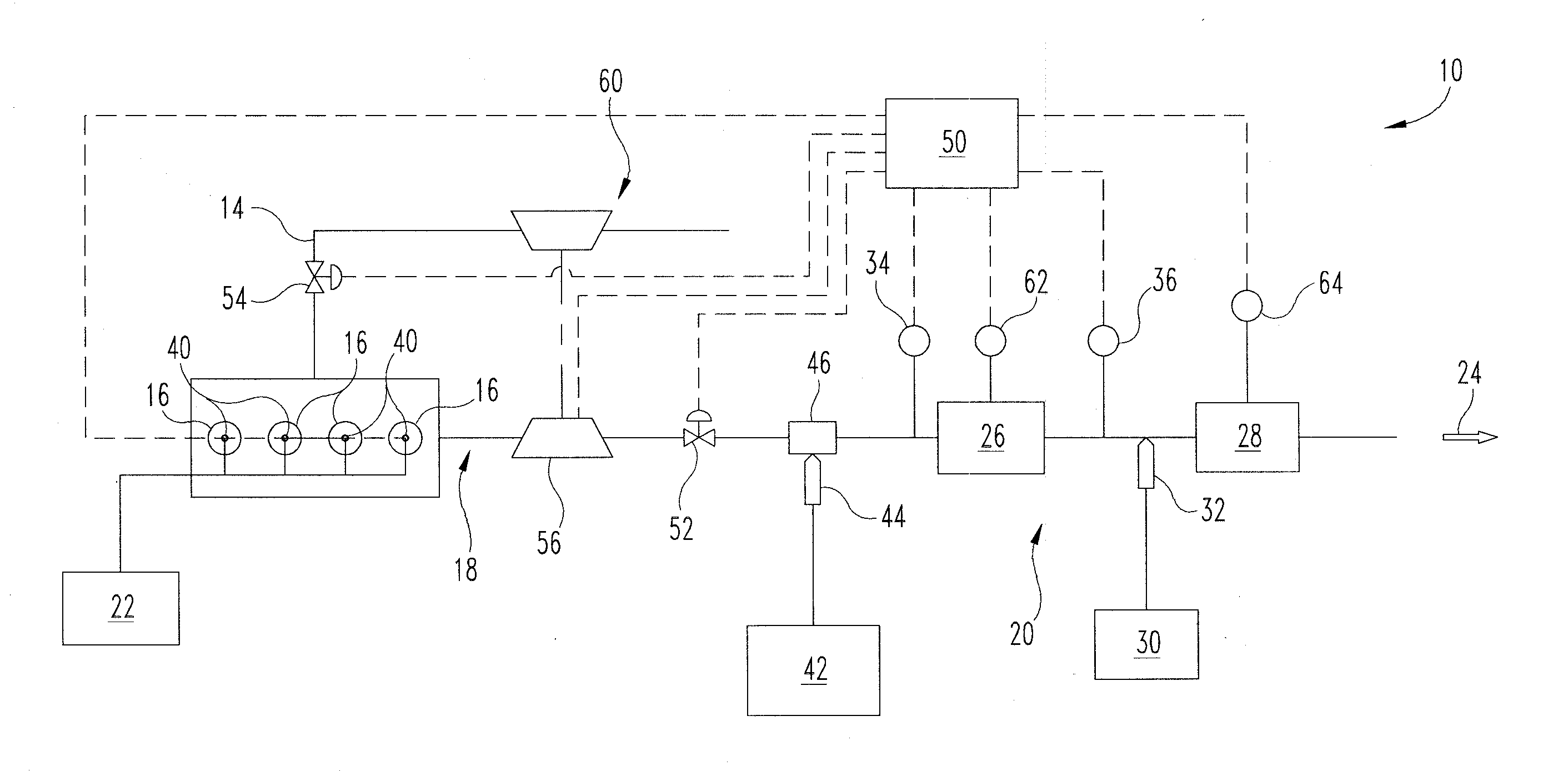
[0012] FIG. 1 is a schematic of one embodiment of an internal combustion engine and aftertreatment system including a passive storage device and a NO.sub.x reduction device.
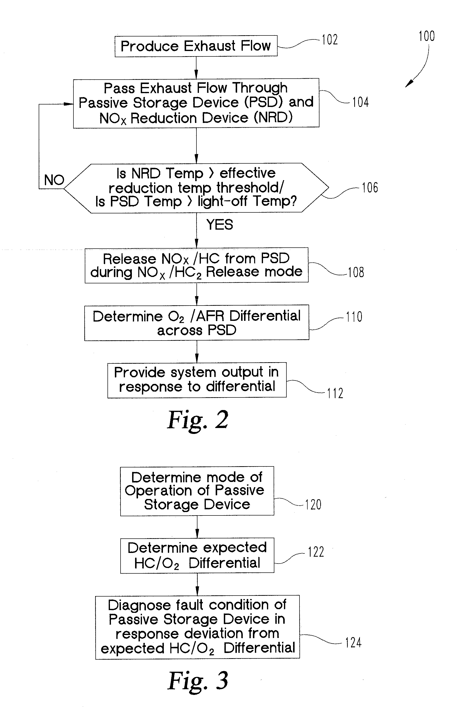
[0013] FIG. 2 is a schematic of a procedure for operating an internal combustion engine and aftertreatment system including a passive storage device and a NO.sub.x reduction device.
[0014] FIG. 3 is a schematic of one embodiment of the procedure of FIG. 2.
[0015] FIG. 4 is a schematic of another embodiment of the procedure of FIG. 2.
[0016] FIG. 5 is a schematic of another procedure for operating an internal combustion engine and aftertreatment system including a passive storage device and a NO.sub.x reduction device.
DETAILED DESCRIPTION
[0017] For the purposes of promoting an understanding of the principles of the invention, reference will now be made to the embodiments illustrated in the drawings and specific language will be used to describe the same. It will nevertheless be understood that no limitation of the scope of the invention is thereby intended, any alterations and further modifications in the illustrated embodiments, and any further applications of the principles of the invention as illustrated therein as would normally occur to one skilled in the art to which the invention relates are contemplated herein.
[0018] As shown in FIG. 1, an exemplary internal combustion engine system 10 includes an internal combustion engine 12 that receives fuel from at least one fuel source 22 and combusts the fuel with a charge flow from intake system 14 in a plurality of cylinders 16. The combusted charge flow/fuel mixture exits cylinders 16 as exhaust gas via an exhaust flow 24 into an exhaust system 18. Exhaust system 18 includes an aftertreatment system 20 that is configured to passively store NO.sub.x and hydrocarbons via, for example, adsorption on a catalyst substrate during certain operating conditions, as discussed further below. In one embodiment, engine 12 is a diesel engine. Engine 12 is shown with four cylinders 16 that may be configured in an in-line arrangement as shown, but any suitable cylinder arrangement and number of cylinders are contemplated.
[0019] Engine 12 receives fuel from fuel source 22 via any suitable arrangement. For example, in the illustrated embodiment, fuel source 22 is connected to cylinders 16 with at least one fuel line and a plurality of direct injectors 40. One or more direct injectors 40 may be associated with each cylinder 16 at any suitable injection location. In other embodiments, the fuel injectors include port injectors, or injection of fuel into intake system 14 upstream of cylinders 16. One or more fuel control valves can control the amount, duration, and timing of fuel injection into cylinders 16. In one embodiment, the direct injectors 40 are operated by a controller 50 to provide a post-combustion injection of fuel that inserts unburned hydrocarbons into the exhaust gas flow for management and control of exhaust gas temperatures. In another embodiment, a hydrocarbon source 42 that is in addition to fuel source 22 is provided with a hydrocarbon injector 44 for injection of hydrocarbons directly into the exhaust stream downstream of cylinders 16. In yet another embodiment, injector 44 is connected to fuel source 22.
[0020] System 10 may further include various features, such as a turbocharger 60, an exhaust gas recirculation system (not shown), a charge air cooler or intercooler (not shown), variable geometry turbine 56, an intake throttle 54, and/or exhaust throttle 52. In any arrangement, aftertreatment system 20 includes a passive storage device 26 that receives exhaust flow 24 from engine 12 and provides passive storage of NO.sub.x that is produced by engine 12 and/or passive storage of hydrocarbons that are injected into the exhaust gas stream or released from the cylinders 16, at least under certain operating conditions. Aftertreatment system 20 also includes a NO.sub.x reduction device 28, such as an SCR catalyst, downstream of passive storage device 26. Aftertreatment system 20 is also connected to a reductant source 30 at a second location that is downstream of the passive NO.sub.x adsorption location and upstream of at least the NO.sub.x reduction device 28. Reductant source 30 can include, for example, diesel exhaust fluid, urea, ammonia derived from urea, ammonia gas, a solid storage media that stores ammonia gas until heated above a threshold release temperature, or any suitable reductant and reductant delivery system. The reductant from reductant source 30 can be delivered to aftertreatment system 20 with a reductant injector 32. Air assisted reductant delivery systems and systems without air assistance are contemplated.
[0021] Aftertreatment system 20 can be connected to any one or more temperature generation devices 46 that provide an output to system 10, such as by increasing or decreasing a temperature of the exhaust flow 24 upstream of passive storage device 26. The temperature generation devices 46 may include an exhaust heating apparatus that includes a source of reductant such as H.sub.2, small and long chain hydrocarbons (liquid or gaseous) that are provided to an optional thermal device, or hydrocarbons (liquid or gaseous) that are injected by hydrocarbon doser or injector 44 upstream of passive storage device 26. Any thermal device is contemplated, including a thermal generator or thermal enhancer, such as a catalytic burner, rich burner, or lean burner. Other temperature generation devices that provide heat to or facilitate the increase in heat of exhaust flow 24 upstream of the passive storage device 26 are contemplated. Temperature generation devices include, for example, fuel injectors such as direct injectors 40 operated by controller 50 to provide the late post-combustion injection of fuel into the exhaust gas produced by the respective cylinder 16. Other temperature generation devices include an exhaust throttle 52 actuated by controller 50, an intake throttle 54 actuated by controller 50, a turbine 56 having a controllable inlet actuated by controller 50 to be positioned in a high exhaust backpressure position, a variable valve timing device (not shown) associated with cylinders 16 operable by controller 50 to vary the lift profile of the valves of cylinders 16 to control exhaust temperatures, and an operating state of engine 12 produced by controller 50 that produces increased exhaust gas temperatures.
[0022] In one embodiment passive storage device 26 is a separate catalyst device that readily passively adsorbs and stores NO.sub.x and hydrocarbons on its surface under low exhaust temperature conditions, and then desorbs this NO.sub.x and oxidizes the stored hydrocarbons as the exhaust temperature increases and therefore as the temperature of passive storage device 26 increases. In a further embodiment, passive storage device 26 is a passive NO.sub.x adsorption washcoat applied to a DOC substrate having hydrocarbon storage capability in low temperature and cold start operating conditions. The washcoat can be applied preferentially on an upstream side of the DOC substrate, preferentially on a downstream side of the DOC substrate, or uniformly on the DOC substrate. In still other embodiments, passive storage device 26 includes a DOC washcoat and a passive NO.sub.x adsorption washcoat applied to a common substrate. Again the passive NO, adsorption washcoat can be applied preferentially upstream, preferentially downstream, or uniformly relative to the oxidation catalyst washcoat. In yet other embodiments of passive storage device 26, the oxidation catalyst is applied as a washcoat to a passive NO.sub.x adsorption substrate. The oxidation catalyst washcoat can be applied preferentially upstream, preferentially downstream, or uniformly on the passive NO.sub.x adsorption substrate. In any arrangement, the passive storage device 26 is configured to release the stored NO.sub.x at an exhaust flow temperature where the temperature of the NO.sub.x reduction catalyst 28 is effective for reducing NO.sub.x to N.sub.2 and H.sub.2O, and or to oxidize stored hydrocarbons when a light-off temperature is reached.
[0023] Aftertreatment system 20 enables NO.sub.x storage on passive storage device 26 in a NO.sub.x storage mode of operation at low exhaust temperatures when NO.sub.x reduction catalyst 28 is not active, and releases the stored NO.sub.x in a NO.sub.x release mode of operation when NO.sub.x reduction catalyst 28 is at a temperature effective for NO.sub.x conversion. In one embodiment, the effective temperature for efficient NO.sub.x conversion by NO.sub.x reduction catalyst 28 is a temperature above about 200.degree. C., although other effective temperature thresholds are contemplated depending on catalyst formulation, feed gas composition, and other parameters. As used herein a low temperature condition is a condition in which the temperature of NO.sub.x reduction catalyst 28 is less than the effective temperature threshold of NO.sub.x reduction catalyst 28.
[0024] The release of NO.sub.x and/or oxidation of hydrocarbons from passive storage device 26 in the release modes of operation can be managed by controlling the heating of passive storage device 26 with one or more of the temperature generation devices 46. The heating of exhaust flow 24 and passive storage device 26 to a NO.sub.x release temperature, NO.sub.x release temperature range, and/or HC oxidation temperature (light-off temperature) can be actively managed, and/or can occur as a result of nominal operations of engine 12. The low temperature storage of NO.sub.x by passive storage device 26 allows delay of injection of reductant from reductant injector 32 until higher operating temperatures for NO.sub.x reduction catalyst 28 are reached, such as those above the effective temperature threshold. Furthermore, in embodiments where second sensor 36 is a NO.sub.x sensor, a reductant injection command can be determined and provided to reductant injector 32 to provide a reductant injection amount that treats the NO.sub.x amount that is released with NO.sub.x reduction catalyst 28.
[0025] System 10 includes controller 50 that is operationally coupled to various sensors, actuators and components of system. The controller 50 may be in communication with any sensor, actuator, datalink, and/or network in the system 10. In FIG. 1, controller 50 is operably connected to a first sensor 34 upstream of passive storage device 26 and a second sensor 36 downstream of passive storage device 26. First sensor 34 can be, for example, an O.sub.2 or lambda sensor, or combination of sensors operable to provide signals indicative of an oxygen amount upstream of passive storage device 26. First sensor 34 can also be a virtual sensor that provides the oxygen amount from calculations involving one or more other operating parameters of engine 12 using any known technique for determining an oxygen amount in the exhaust flow. In one embodiment, second sensor 36 is a NO.sub.x sensor that includes various signal components, one of which is an oxygen component signal that provides a signal indicative of an oxygen amount downstream of passive storage device 26. Second sensor 36 also provides a measurement of a NO.sub.x amount that is released from passive storage device 26. In still other embodiments, second sensor 36 could be an O.sub.2 or lambda sensor instead of, or in addition to, a NO.sub.x sensor. Controller 50 may also be connected to other sensors, such as temperature sensor 64 that measures an exhaust temperature at or near NOx reduction device 28 (or a temperature sensor at passive storage device 26), or temperature sensor(s) anywhere along the exhaust system and/or at any component of the exhaust system. Controller 50 may also be connected to sensors that provide NO.sub.x amounts, ammonia amounts, pressure conditions, and engine operating parameters, for example. Controller 50 is operable to interpret the operating parameters and signals and control one or more outputs of system 10 in response thereto.
[0026] In one embodiment, the output from controller 50 includes a determination that the passive storage device 26 is operating in a NO.sub.x storage mode or a NO.sub.x release mode. Using sensors 34, 36, the oxygen amount differential across the passive storage device 26 can be determined and used to interpret the mode of operation. For example, if the passive storage device 26 is in a NO.sub.x storage mode, the inlet oxygen amount to the passive storage device 26 is greater than the outlet oxygen amount from the passive storage device 26 since NO.sub.x is stored on passive storage device 26. If the passive storage device 26 is in a NOx release mode of operation, the oxygen amount to the inlet of the passive storage device 26 is less than the oxygen amount from the outlet of the passive storage device 26.
[0027] In a further embodiment, the output from controller 50 includes a determination that the passive storage device 26 is operating in a HC storage mode or a HC release mode. Using sensors 34, 36, the air-fuel ratio differential across the passive storage device 26 can be determined from oxygen amounts and hydrocarbon amounts in the exhaust gas and used to interpret the mode of operation. For example, if the passive storage device 26 is in a HC storage mode, the inlet air-fuel ratio to the passive storage device 26 is greater than the outlet air-fuel ratio from the passive storage device 26 since hydrocarbons are stored on passive storage device 26. If the passive storage device 26 is in a HC release mode of operation, the air-fuel ratio to the inlet of the passive storage device 26 is less than the air-fuel ratio from the outlet of the passive storage device 26 due to hydrocarbon oxidation.
[0028] The oxygen amount downstream of the passive storage device 26 can be measured by second sensor 36 that includes, for example, a NO.sub.x sensor with an oxygen amount sensing component, a dedicated oxygen sensor, or other suitable sensor from which an oxygen amount can be determined. The oxygen amount upstream of the passive storage device 26 can be measured by a first sensor 34 that is an oxygen sensor, a virtual sensor that determines the engine out NO.sub.x amount from the outputs of one or more other sensors, an engine-out NO.sub.x sensor with an oxygen amount sensing component, or other suitable device or method for determining the oxygen amount. In still another embodiment, a single sensor 62 is provided that measures the oxygen amount differential across passive storage device 26. In still other embodiments, the mode of operation of passive storage device 26 is determined additionally or alternatively from a temperature condition of the aftertreatment system 20.
[0029] In a further embodiment, the system output from controller 50 in response to the oxygen amount differential across passive storage device 26 is a diagnostic of NO.sub.x storage capabilities of the passive storage device 26. The passive storage device 26 is diagnosed by determining that the oxygen amount differential across passive storage device 26 deviates from an expected differential by more than a threshold amount. For example, in a NO.sub.x storage mode of operation, the expected oxygen amount differential should indicate, for example, a negative oxygen amount differential between the downstream and upstream sides of passive storage device 26. If the actual oxygen amount differential is near 0 or positive in a NO.sub.x storage mode of operation, then a fault condition of the passive storage device can be output in response to the actual or measured oxygen amount differential exceeding the expected oxygen amount differential by more than a threshold amount. One or more faults over a time period or segment of engine operation can be used to determine a service condition exists for passive storage device 26.
[0030] In a further embodiment, the system output from controller 50 in response to the oxygen amount differential across passive storage device 26 is a diagnostic for a second sensor 36 that is a NO.sub.x sensor. For example, during a NO.sub.x storage mode of operation, the output of the NO.sub.x sensor 36 can be compared to an expected output of the NO.sub.x sensor 36, and a NO.sub.x sensor fault condition can be determined by a deviation of the actual NO.sub.x sensor output from the expected NO.sub.x sensor output by more than a threshold amount. In a NO.sub.x release mode of operation of the passive storage device 26, an expected NO.sub.x amount could be estimated from the NO.sub.x amount stored by the passive storage device 26. The expected and actual NO.sub.x sensor outputs could be a release rate of NO.sub.x from passive storage device 26 or an accumulated amount of NO.sub.x released over a time period. A NO.sub.x sensor failure condition can be provided in response to one or more NO.sub.x sensor faults over a predetermined period of time or amount of engine operation.
[0031] Also contemplated are methods and procedures associated with the systems described above. For example, referring to FIG. 2, a procedure 100 includes an operation 102 to operate an internal combustion engine to produce an exhaust flow. Procedure 100 further includes an operation 104 to pass the exhaust flow through an aftertreatment system including at least a passive storage device and a NO.sub.x reduction device downstream of the passive storage device. At least one of the NO.sub.x and hydrocarbons in the exhaust flow is passively stored with the passive storage device during a storage mode of operation when the exhaust flow is in a low temperature condition. Procedure 100 includes a conditional 106 to determine if a temperature of the NOx reduction catalyst is greater than an effective reduction temperature threshold, and/or of the temperature of the passive storage device is greater than a light-off threshold. If conditional 106 is negative, procedure 100 returns to operation 104. If conditional 106 is positive, procedure 100 continues at operation 108 to release NO.sub.x and/or hydrocarbons from the passive storage device in a release mode of operation when the NO.sub.x reduction device is above the effective reduction temperature threshold for reducing NO.sub.x across the NO.sub.x reduction device and/or the passive storage device exceed the light-off temperature threshold.
[0032] In one embodiment, the procedure 100 includes an operation 110 to determine a differential between an oxygen amount downstream of the passive storage device and an oxygen amount upstream of the passive storage device, and an operation 112 to provide a system output in response to the differential. In another embodiment, the method includes determining a differential between an air-fuel ratio downstream of the passive storage device and an air-fuel ratio (AFR) upstream of the passive storage device and providing a system output in response to the air-fuel ratio differential.
[0033] Referring to FIG. 3, in one embodiment of procedure 100, there includes an operation 120 to determine whether the passive storage device is in the NO.sub.x storage mode of operation or the NO.sub.x release mode of operation and, in response to the mode of operation, an operation 122 to determine an expected differential between the oxygen and/or the hydrocarbon amount downstream of the passive storage device and upstream of the passive storage device. An operation 124 for providing the system output includes a diagnosis of a fault condition of the passive storage device in response to a deviation of the determined actual differential deviating from the expected hydrocarbon and/or oxygen differential by more than a threshold amount.
[0034] In certain embodiments of method 100, operation 124 to diagnose the fault condition includes determining the actual differential of an oxygen amount by measuring an oxygen amount downstream of the passive storage device and measuring an oxygen amount upstream of the passive storage device. Measuring the oxygen amount downstream of the passive storage device can include determining an oxygen component of an output of a NO.sub.x sensor downstream of the passive storage device, and/or determining a lambda sensor or lambda sensor oxygen component. In a further embodiment, measuring the oxygen amount upstream of the passive storage device includes measuring the oxygen amount with an oxygen sensor. In an alternative embodiment, measuring the oxygen amount upstream of the passive storage device includes determining the oxygen amount from one or more operating parameters of the engine that provide an indication of an oxygen amount that is produced in the exhaust resulting from the combustion process in each cylinder.
[0035] In certain further embodiments, operation 120 includes determining a HC storage function of the passive storage device in response to an air-fuel ratio determined from the oxygen amounts and hydrocarbons amounts. A HC release mode of operation and. HC storage mode of operation of the passive storage device is determined in response to the air-fuel ratio differentials upstream and downstream of the passive storage device. In another embodiment, a health of the passive storage device is diagnosed in response to an expected air fuel ratio downstream of the passive storage device deviating from an expected air-fuel ratio by more than a threshold amount.
[0036] In yet another embodiment, the operation 122 to determine the differential includes measuring a difference between an oxygen amount downstream of the passive storage device and an oxygen amount upstream of the passive storage device, using one of the upstream and downstream oxygen amounts as a reference oxygen amount.
[0037] In another embodiment, the system output for operation 120 is one of a NO.sub.x storage mode of operation and a NO.sub.x release mode of operation of the passive storage device. In a refinement of this embodiment, the method includes determining an expected output of a NO.sub.x sensor downstream of the passive storage device in response to the mode of operation and determining a fault condition of the NO.sub.x sensor in response to a measured output of the NO.sub.x sensor deviating from the expected output by more than a threshold amount.
[0038] In a further embodiment, the NO.sub.x reduction device is a SCR catalyst and the aftertreatment system includes a reductant source operationally to provide an ammonia based reductant upstream of the SCR catalyst and downstream of the passive storage device. In another embodiment, operation 112 to provide the system output includes at least one of modulating a NO.sub.x output of the engine and modulating a temperature of the exhaust flow.
[0039] In another procedure 150 in FIG. 5, there is an operation 152 to operate an internal combustion engine to produce an exhaust flow and an operation 154 to pass the exhaust flow through an aftertreatment system including at least a passive storage device and a NO.sub.x reduction device downstream of the passive storage device. The procedure 100 can include an operation 156 to store hydrocarbons from the exhaust flow with the passive storage device during a hydrocarbon storage mode of operation when the exhaust flow is in a low temperature condition. Procedure 150 further includes an operation 158 to oxidize hydrocarbons stored by the passive storage device in a hydrocarbon release mode of operation when the passive storage device is above a light-off temperature. Procedure 150 continues at operation 160 to determine a differential between an air-fuel ratio downstream of the passive storage device and an air-fuel ratio upstream of the passive storage device, and an operation 162 to provide a system output in response to the differential.
[0040] In yet another embodiment shown in FIG. 4, procedure 100 includes operating the internal combustion engine to produce an exhaust flow to an aftertreatment system including at least a passive storage device and a NO.sub.x reduction device downstream of the passive storage device, and storing NO.sub.x in the exhaust flow with the passive storage device during a NO.sub.x storage mode of operation when the exhaust flow and/or storage device is in a low temperature condition. The procedure includes an operation to release NO.sub.x from the passive storage device in a NO.sub.x release mode of operation when the NO.sub.x reduction device is above an effective reduction temperature threshold for reducing NO.sub.x across the NO, reduction device. Procedure 100 further includes an operation 130 to determine a NO.sub.x amount released from the passive storage device during the NO.sub.x release mode of operation with a NO.sub.x sensor between the passive storage device and the NO.sub.x reduction device, and an operation 132 to inject a reductant amount into the exhaust flow upstream of the NO.sub.x reduction device in response to the NO.sub.x amount released.
[0041] While the invention has been illustrated and described in detail in the drawings and foregoing description, the same is to be considered as illustrative and not restrictive in character, it being understood that only certain exemplary embodiments have been shown and described. Those skilled in the art will appreciate that many modifications are possible in the example embodiments without materially departing from this invention. Accordingly, all such modifications are intended to be included within the scope of this disclosure as defined in the following claims.
[0042] In reading the claims, it is intended that when words such as "a," "an," "at least one," or "at least one portion" are used there is no intention to limit the claim to only one item unless specifically stated to the contrary in the claim. When the language "at least a portion" and/or "a portion" is used the item can include a portion and/or the entire item unless specifically stated to the contrary.
* * * * *
D00000
D00001
D00002
D00003
XML
uspto.report is an independent third-party trademark research tool that is not affiliated, endorsed, or sponsored by the United States Patent and Trademark Office (USPTO) or any other governmental organization. The information provided by uspto.report is based on publicly available data at the time of writing and is intended for informational purposes only.
While we strive to provide accurate and up-to-date information, we do not guarantee the accuracy, completeness, reliability, or suitability of the information displayed on this site. The use of this site is at your own risk. Any reliance you place on such information is therefore strictly at your own risk.
All official trademark data, including owner information, should be verified by visiting the official USPTO website at www.uspto.gov. This site is not intended to replace professional legal advice and should not be used as a substitute for consulting with a legal professional who is knowledgeable about trademark law.