Organic Rankine Cycle System With Lubrication Circuit
FORTINI; Matthew ; et al.
U.S. patent application number 14/811276 was filed with the patent office on 2015-12-31 for organic rankine cycle system with lubrication circuit. The applicant listed for this patent is EATON CORPORATION. Invention is credited to William Nicholas EYBERGEN, Matthew FORTINI, Lalit Murlidhar PATIL, Sheetalkumar Shamrao PATIL, Tapan Vasant PONKSHE, Martin D. PRYOR, Bradley WRIGHT.
| Application Number | 20150377080 14/811276 |
| Document ID | / |
| Family ID | 54929984 |
| Filed Date | 2015-12-31 |


View All Diagrams
| United States Patent Application | 20150377080 |
| Kind Code | A1 |
| FORTINI; Matthew ; et al. | December 31, 2015 |
ORGANIC RANKINE CYCLE SYSTEM WITH LUBRICATION CIRCUIT
Abstract
A Rankine cycle system including a Rankine cycle working circuit and a lubrication circuit is disclosed. The lubrication circuit and the Rankine cycle working circuit include a shared segment including a mixture of Rankine cycle working fluid from the Rankine cycle working circuit and lubricant from the lubrication circuit. A separator receives the mixture of Rankine cycle working fluid and lubricant from the shared segment and separates the Rankine cycle working fluid from the lubricant. The separated Rankine cycle working fluid is directed along the Rankine cycle working circuit from the separator to the heating zone and the separated lubricant is directed along the lubrication circuit from the separator to a mechanical expander. The working fluid and lubricant are recombined after passing separately through the expander and are then introduced to the condensing zone.
| Inventors: | FORTINI; Matthew; (Livonia, MI) ; EYBERGEN; William Nicholas; (Harrison Twp., MI) ; PATIL; Lalit Murlidhar; (Pune, IN) ; PONKSHE; Tapan Vasant; (Pune, IN) ; WRIGHT; Bradley; (Livonia, MI) ; PRYOR; Martin D.; (Canton, MI) ; PATIL; Sheetalkumar Shamrao; (Pune, IN) | ||||||||||
| Applicant: |
|
||||||||||
|---|---|---|---|---|---|---|---|---|---|---|---|
| Family ID: | 54929984 | ||||||||||
| Appl. No.: | 14/811276 | ||||||||||
| Filed: | July 28, 2015 |
Related U.S. Patent Documents
| Application Number | Filing Date | Patent Number | ||
|---|---|---|---|---|
| PCT/US2014/013397 | Jan 28, 2014 | |||
| 14811276 | ||||
| 61757533 | Jan 28, 2013 | |||
| Current U.S. Class: | 60/657 ; 60/671 |
| Current CPC Class: | F01K 25/10 20130101; F01D 25/18 20130101; F01K 23/065 20130101; F01K 21/005 20130101; F01K 25/06 20130101 |
| International Class: | F01K 25/10 20060101 F01K025/10 |
Goverment Interests
GOVERNMENT LICENSE RIGHTS
[0002] This invention was made with government support under Contract No. DE-EE0005650 awarded by the National Energy Technology Laboratory funded by the Office of Energy Efficiency & Renewable Energy of the United States Department of Energy. The government has certain rights in the invention.
Foreign Application Data
| Date | Code | Application Number |
|---|---|---|
| Dec 9, 2014 | IN | 3611/DEL/2014 |
Claims
1. A Rankine cycle system comprising: a. a separator for separating a working fluid from a lubricant, the separator having a first inlet for receiving a working fluid and lubricant mixture, a first outlet for discharging the working fluid, and a second outlet for discharging the lubricant; b. a mechanical expander having a working fluid inlet in fluid communication with the separator first outlet, a lubricant circuit inlet in fluid communication with the separator second outlet, a working fluid outlet, and a lubricant circuit outlet in direct fluid communication with the working fluid outlet; c. a mixing location at which the lubricant from the lubricant circuit outlet is mixed with the working fluid from the working fluid outlet to form the working fluid and lubricant mixture; d. a condenser in direct fluid communication with the mixing location; and e. a fluid pump in fluid communication with the condenser and the separator, the fluid pump being for receiving the working fluid and lubricant mixture from the condenser and discharging the working fluid and lubricant mixture to the separator.
2. The Rankine cycle system of claim 1, wherein: a. the system is configured such that the mechanical separator lubricant inlet is above the first outlet of the separator.
3. The Rankine cycle system of claim 1, wherein the separator includes a pipe directing the working fluid and lubricant mixture around an inside surface of the separator.
4. The Rankine cycle system of claim 1, wherein the separator includes a diverter plate.
5. The Rankine cycle system of claim 4, wherein the diverter plate includes an open center.
6. The Ranking cycle system of claim 1, wherein the separator includes a plurality of converging inlet branches extending from an interior volume of the separator to the separator first outlet.
7. The Rankine cycle system of claim 1, further including a control valve located between the separator second outlet and the mechanical expander lubricant circuit inlet, the control valve being configured to regulate a flow rate of lubricant through the mechanical expander.
8. The Rankine cycle system of claim 1, wherein the Rankine cycle working circuit is an organic Rankine cycle working circuit.
9. The Rankine cycle system of claim 1, wherein the Rankine cycle working fluid is an organic solvent.
10. The Rankine cycle system of claim 9, wherein the Rankine cycle working fluid is selected from the group consisting of ethanol, n-pentane, and toluene.
11. The Rankine cycle system of claim 1, wherein the lubricant is an oil.
12. The Rankine cycle system of claim 1, wherein the Rankine cycle working fluid is heated at a heating zone by waste heat from a prime mover.
13. The Rankine cycle system of claim 12, wherein the prime mover is selected from the group consisting of an internal combustion engine and a fuel cell.
14. The Rankine cycle system of claim 1, wherein the mechanical expander includes a fixed displacement expander.
15. The Rankine cycle system of claim 14, wherein the mechanical expander is a three stage volumetric expander.
16. A Rankine cycle system comprising: a. an organic working fluid; b. a condenser for condensing the organic working fluid to form condensed organic working fluid; c. a heat exchanger for heating the organic working fluid to form heated organic working fluid; d. a fixed displacement mechanical expansion device for extracting energy from the organic working fluid, the mechanical expansion device including first and second interleaved non-contacting rotors each having an equal number of a plurality of lobes mounted on a shaft, the mechanical expansion device including intermeshing timing gears that coordinate rotation of the rotors and prevent the lobes of the first and second interleaved rotors from contacting each other, the mechanical expansion device including a housing having an inlet, an outlet, and an interior region that provides fluid communication between the inlet and the outlet, the interior region including first and second rotor bores in which the first and second rotors are respectively positioned, the first and second rotors defining fluid transfer volumes between the lobes that transfer the working fluid circumferentially about the bores from the inlet to the outlet, and at least one of the shafts defining an output shaft; e. a pump positioned between the condenser and the heat exchanger for pumping the condensed organic working fluid received from the condenser to the heat exchanger, wherein the heated organic working fluid flows from the heat exchanger to the inlet of the mechanical expansion device, and wherein expanded working fluid flows from the outlet of the mechanical expansion device to the condenser; f. the condenser, the heat exchanger, and the fixed displacement mechanical expansion device being part of a Rankine cycle working circuit through which the organic working fluid is circulated; g. a lubrication circuit for lubricating the fixed displacement mechanical expansion device; h. the lubrication circuit and the Rankine cycle working circuit including a shared segment including a mixture of the organic working fluid from the Rankine cycle working circuit and lubricant from the lubrication circuit; and i. a separator that receives the mixture of organic working fluid and lubricant from the shared segment and separates the organic working fluid from the lubricant, wherein the separated organic working fluid is directed along the Rankine cycle working circuit from the separator to the heat exchanger and the separated lubricant is directed along the lubrication circuit from the separator to the fixed displacement mechanical expansion device.
17. The Rankine cycle system of claim 16, wherein the pump drives flow of the organic working fluid through the Rankine cycle working circuit and also drives flow of the lubricant through the lubrication circuit.
18. The Rankine cycle system of claim 16, wherein the pump is positioned along the shared segment.
19. The Rankine cycle system of claim 16, wherein the lubricant leaving the expansion device is combined with the organic working fluid leaving the expansion device at a location between the condenser and the pump.
20. The Rankine cycle system of claim 1, further including a control valve located between the separator second outlet and the mechanical expander lubricant circuit inlet, the control valve being configured to regulate a flow rate of lubricant through the mechanical expander.
Description
RELATED APPLICATIONS
[0001] This application is a continuation-in-part of and claims priority to Patent Cooperation Treaty International Application Number PCT/US2014/013397, filed on Jan. 28, 2014. This application also claims priority to U.S. Provisional patent application No. 61/757,533, filed on Jan. 28, 2013 and to India Provisional patent application number 3611/DEL/2014, filed on Sep. 12, 2014. The entireties of U.S. 61/757,533, India 3611/DEL/2014 and PCT/US2014/013397 are incorporated by reference herein.
TECHNICAL FIELD
[0003] The present disclosure relates to systems for recovering waste heat. More particularly, the present disclosure relates to organic Rankine cycle systems.
BACKGROUND
[0004] The Rankine cycle is a power generation cycle that converts thermal energy to mechanical work. The Rankine cycle is typically used in heat engines, and accomplishes the above conversion by bringing a working substance from a higher temperature state to a lower temperature state. The classical Rankine cycle is the fundamental thermodynamic process underlying the operation of a steam engine.
[0005] The Rankine cycle typically employs individual subsystems, such as a condenser, a fluid pump, a heat exchanger such as a boiler, and an expander turbine. The pump is frequently used to pressurize the working fluid that is received from the condenser as a liquid rather than a gas. The pressurized liquid from the pump is heated at the heat exchanger and used to drive the expander turbine so as to convert thermal energy into mechanical work. Upon exiting the expander turbine, the working fluid returns to the condenser where any remaining vapor is condensed. Thereafter, the condensed working fluid returns to the pump and the cycle is repeated.
[0006] A variation of the classical Rankine cycle is the Organic Rankine cycle (ORC), which is named for its use of an organic, high molecular mass fluid, with a liquid-vapor phase change, or boiling point, occurring at a lower temperature than the water-steam phase change. As such, in place of water and steam of the classical Rankine cycle, the working fluid in the ORC may be a solvent, such as n-pentane or toluene. The ORC working fluid allows Rankine cycle heat recovery from lower temperature sources such as biomass combustion, industrial waste heat, geothermal heat, solar ponds, etc. The low-temperature heat may then be converted into useful work, which may in turn be converted into electricity.
[0007] Further development in such Rankine cycle systems is desired.
SUMMARY
[0008] One aspect of the present disclosure relates to a closed-loop organic Rankine cycle system including a Rankine cycle working circuit and a lubrication circuit. In certain examples, the Rankine cycle working circuit and the lubrication circuit have portions that coincide with one another. In certain examples, the Rankine cycle working circuit and the lubrication circuit share a common hydraulic pump. In certain examples, lubricant from the lubrication circuit and working fluid from the Rankine cycle working circuit are allowed to mix with each other. In certain examples, the lubrication circuit is a cooling circuit that cools lubricant used to lubricate and cool components (e.g. bearings, timing gears, etc.) of a mechanical expander that extracts energy/work from the Rankine cycle working circuit. In certain examples, lubricant from the lubrication circuit mixes with working fluid of the Rankine cycle working circuit and provides lubrication to a hydraulic pump that drives flow through both the Rankine cycle working circuit and the lubrication circuit.
[0009] Aspects of the present disclosure allow for a simplified Rankine cycle system having reduced sealing considerations and reduced pumping components. In certain examples, a separator is used to separate lubricant from the Rankine cycle working fluid before the Rankine cycle working fluid is delivered to a heat exchanger. In certain examples, the Rankine cycle system is used to re-capture energy from waste heat from a prime mover such as an internal combustion engine, a fuel cell, or a similar component. In certain examples, Rankine cycle system is used to re-capture energy from waste heat from the prime mover of a vehicle.
[0010] A variety of additional aspects will be set forth in the description that follows. These aspects can relate to individual features and to combinations of features. It is to be understood that both the foregoing general description and the following detailed description are exemplary and explanatory only and are not restrictive of the broad concepts upon which the embodiments disclosed herein are based.
BRIEF DESCRIPTION OF THE DRAWINGS
[0011] FIG. 1 is a schematic depiction of a Rankine cycle system employing a Rankine cycle working circuit and a lubrication circuit having features that are examples of inventive aspects in accordance with the principles of the present disclosure;
[0012] FIG. 1A is a schematic depiction of a simplified Rankine cycle working circuit and lubrication circuit having shared features with the circuits shown in FIG. 1.
[0013] FIG. 2 is a perspective view of an example configuration for a separator that can be used in the Rankine cycle systems of FIGS. 1 and 2;
[0014] FIG. 2A is a perspective view of an example configuration for a separator that can be used in the Rankine cycle systems of FIGS. 1 and 2;
[0015] FIG. 3 is a top view of the separator shown in FIG. 2;
[0016] FIG. 4 is a bottom view of the separator shown in FIG. 2;
[0017] FIG. 5 is a first side view of the separator shown in FIG. 2;
[0018] FIG. 6 is a second side view of the separator shown in FIG. 2;
[0019] FIG. 7 is a cross-sectional side view of the separator shown in FIG. 2;
[0020] FIG. 8 is a cross-sectional side view of a portion of the separator shown in FIG. 2;
[0021] FIG. 9 is a perspective cross-sectional view of the separator shown in FIG. 2;
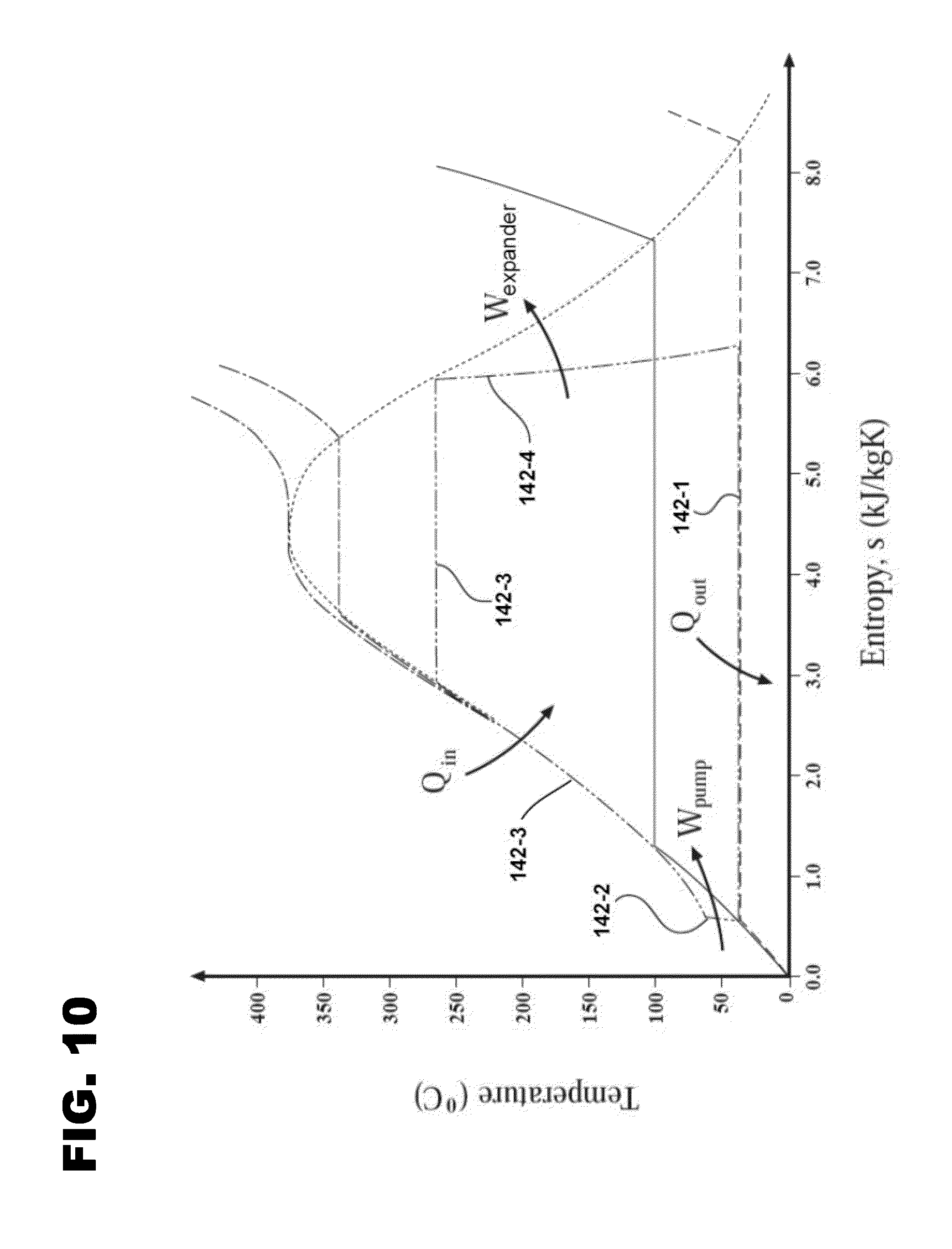
[0022] FIG. 10 is a diagram depicting the Rankine cycle employed by the system shown in FIG. 1;
[0023] FIG. 11 is a cross-sectional schematic view of a single stage Roots-style expander suitable for use in extracting mechanical energy from the system of FIG. 1;
[0024] FIG. 12 is a schematic depiction of the Roots-style expander of FIG. 11;
[0025] FIG. 13 is a cross-sectional view showing timing gears of the Roots-style expander of FIG. 11; and
[0026] FIG. 14 schematically depicts a vehicle including a Rankine cycle system in accordance with the principles of the present disclosure.
DETAILED DESCRIPTION
[0027] Referring to the drawings wherein like reference numbers correspond to like or similar components throughout the several figures.
[0028] The present disclosure relates generally to a Rankine cycle system (e.g., an organic Rankine cycle system) that utilizes heat from a heat source to generate useful work. In one example, the heat source is waste heat from a device such as a prime mover (e.g., an internal combustion engine such as a diesel engine or spark ignition engine, a fuel cell, etc.). In one example, a mechanical device, such as a rotary expander, is used to extract mechanical energy from the Rankine cycle system. In one example, the Rankine cycle system is an organic Rankine cycle system that heats and vaporizes the Rankine cycle working fluid (e.g., a solvent such as ethanol, n-pentane, toluene or other solvents) to temperatures that can equal or exceed 250 degrees Celsius (C).
[0029] Such high temperatures can deteriorate the lubricating oil used to lubricate moving components (e.g., bearings, gears, etc.) of mechanical devices (e.g., rotary expanders) used to extract energy from the Rankine cycle circuit. In this regard, with respect to flowable lubricating oils, it is desirable to use a lubrication cooling circuit that maintains the lubricant at acceptable temperatures. Grease typically is not effective because the solvent forming the Rankine cycle working fluid can cause de-greasing. Furthermore, grease will deteriorate at high temperatures. Lubricating oils can present issues when ineffective sealing (e.g., at mechanical components such as expanders, pumps or other components with moving parts that require lubrication) allows such oils to mix with the Rankine cycle working fluid. For example, lubricant within the Rankine cycle working fluid can be detrimental to the evaporation process by fouling the evaporator coils.
[0030] Aspects of the present disclosure relate to a closed-loop organic Rankine cycle system including a Rankine cycle working circuit and a lubrication circuit. In certain examples, the Rankine cycle working circuit and the lubrication circuit are configured such that lubricant from the lubrication circuit intentionally mixes with the Rankine cycle working fluid. In this way, the Rankine cycle working circuit and the lubrication circuit have portions that coincide with one another. In certain examples, the Rankine cycle working circuit and the lubrication circuit share a common hydraulic pump. In certain examples, the lubricant and the Rankine cycle working fluid mix at a location upstream from a low pressure side of the pump, and a separator separates the Rankine cycle working fluid from the lubricant at a location between a high pressure side of the pump and an evaporator. In certain examples, the lubrication circuit is a cooling circuit that cools lubricant used to lubricate components (e.g. bearings, timing gears, etc.) of a mechanical expander that extracts energy/work from the Rankine cycle working circuit, and lubricant from the lubrication circuit mixes with working fluid of the Rankine cycle working circuit and provides lubrication to a hydraulic pump that drives flow through both the Rankine cycle working circuit and the lubrication circuit. Patent Cooperation Treaty patent application publication WO 2014/117156 shows such a system, wherein the lubricant is mixed with the working fluid after being condensed to remove heat energy from the lubricant which was captured during expander component lubrication. WO '156 is incorporated herein by reference in its entirety. In certain examples, the Rankine cycle system is used to capture energy from waste heat.
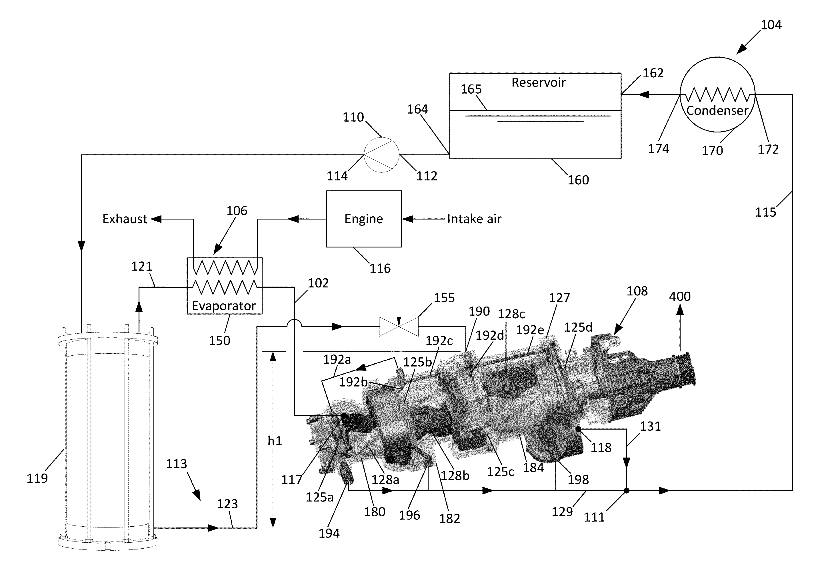
[0031] FIGS. 1 and 1A illustrate an organic Rankine cycle system 100 in accordance with the principles of the present disclosure. The organic Rankine cycle system 100 is configured to convert heat energy from a heat source, such as an engine 116, into mechanical energy. The organic Rankine cycle system 100 is configured to cycle a Rankine cycle working fluid (e.g., a solvent such as ethanol, n-pentane, toluene or other solvents) repeatedly through a closed-loop organic Rankine cycle. As depicted at FIG. 1, the organic Rankine cycle system 100 includes a Rankine cycle working circuit 102 having a condensing zone 104, a heating zone 106, and a mechanical energy extracting zone 108. A hydraulic pump 110 is used to move the working fluid through the Rankine cycle circuit 102. The pump 110 includes a low pressure side 112 in fluid communication with the condensing zone 104, via a reservoir 160, and a high pressure side 114 in fluid communication with the heating zone 106. The mechanical energy extracting zone 108 has an inlet side 117 in fluid communication with the heating zone 106 and an outlet side 118 in fluid communication with the condensing zone 104.
[0032] The Rankine cycle system 100 also includes a lubrication circuit 113 for cycling/circulating and cooling lubricant (e.g., castor oil, synthetic oil, other oils or lubricating material) used to lubricate moving parts associated with a mechanical component (e.g., a rotary expander) of the mechanical energy extracting zone 108. The Rankine cycle working circuit 102 and the lubrication circuit 113 include a shared segment 115 in which the Rankine cycle working fluid and the lubricant are mixed with each other. The Rankine cycle working circuit 102 and the lubrication circuit 113 are co-extensive along the shared segment 115 which feeds into the inlet 172 of a condenser 170. The condensed fluid is delivered from an outlet 174 of the condenser 170 to an inlet 162 of a fluid reservoir 160. The condenser 170 is preferably constructed such that lubricant cannot pool or become otherwise trapped within the condenser and can freely flow to the reservoir 160.
[0033] The pump 110 is positioned in fluid communication with the fluid reservoir 160 such that the mixture of Rankine cycle working fluid and lubricant flows from an outlet 164 of the reservoir 160 and through the pump 110 from the low pressure side 112 to the high pressure side 114. The lubricant within the mixture assists in lubricating the pump 110. The pump 110 provides positive pressure for cycling flow through both the Rankine cycle working circuit 102 and the lubrication circuit 113.
[0034] In the configuration shown at FIG. 1A, the shared segment 115 starts at a primary mixing location 111 located between the condensing zone 104 and the low pressure side 112 of the pump 110, and extends from the primary mixing location 111, through the pump 110 to a fluid separator 119. Lubricant can be metered into the Rankine cycle working fluid at the primary mixing location 111. In this configuration, the separated lubricant bypasses the condenser 104 such that the relatively cool working fluid leaving the condenser can aid in cooling the separated lubricant leaving the energy extracting zone 108.
[0035] In the configuration shown at FIG. 1A, the shared segment 115 starts at a primary mixing location 111 located between the energy extracting zone 108 and the condensing zone 104, and extends from the primary mixing location 111, through the condensing zone 104, the reservoir 160, the pump 112 to the fluid separator 119. In this configuration, the working fluid and lubricant are mixed upstream of the condensing zone 104 such that the condensing zone 104 acts to simultaneously cool the working fluid and the lubricant.
[0036] The fluid separator 119 is configured to separate the lubricant from the Rankine cycle working fluid. The Rankine cycle working circuit 102 includes a non-shared segment 121 that includes Rankine cycle working fluid without lubricant. The non-shared segment 121 extends from the separator 119, through the heating zone 106, and the mechanical energy extracting zone 108. The lubrication circuit 113 includes a non-shared segment 123 that extends from the separator 119 to the mechanical energy extracting zone 108. In one example, the non-shared segment 123 is provided with a control valve 155, such as a needle valve, for controlling the flow rate and/or pressure of the lubricant as it is introduced into the mechanical expander 127 at an inlet 190. Such control is desirable as the introduction of excess lubricant will increase and/or introduce parasitic losses by increases friction at the gears and/or bearings of the expander 127. As shown, the system 100 is configured such that the expander lubrication inlet 190 is above the lubrication outlet 526 of the separator 119 to prevent lubricant from completely draining from the separator 119 to the expander 127 when the system 100 is shut down. In one example, the lubrication outlet 526 is above the lubrication inlet 190 by a height, hl. In one example, the system 100 is configured such that the lowest part of the expander 127 is above the lubrication outlet 526. In one example, the non-shared segment 123 includes lubricant without Rankine cycle working fluid. At the mechanical energy extracting zone 108, the lubricant can flow through lubricant containing structures 125 such as bearings, bearing chambers, and gear chambers of a rotary mechanical expander 127. From the lubricant containment structures 125 (125a, 125b, 125c, 125d) of the mechanical energy extracting zone 108, the lubricant can flow to the primary mixing location 111 via segment 129.
[0037] In certain examples, Rankine cycle working fluid can leak past the shaft seals of expander 127 into the lubricant containment structures 125 such that the segment 129 carries a mixture of lubricant and Rankine cycle working fluid. In this example, the leakage of Rankine cycle working fluid into the lubrication circuit 113 at the mechanical expander 127 does not pose an issue for the system because of the ability to subsequently separate the lubricant from the Rankine cycle working fluid. Likewise, some of the Rankine cycle working fluid may migrate through seals in the expander 127 such that segment 131 carries a mixture of lubricant and Rankine cycle working fluid. Thus, special sealing used to absolutely prevent leakage is not needed thereby reducing the quantity and/or expense of the seals in the system.
[0038] In one example, the fluid separator 119 separates the Rankine cycle working fluid from the lubricant and directs the Rankine cycle working fluid to the non-shared segment 121 and the lubricant to the non-shared segment 123. Pressure from the pump 110 drives flow of the Rankine cycle working fluid through the non-shared segment 121 and also drives flow of lubricant through the non-shared segment 123. The mechanical expander 127 can include one or more rotor chambers 128 (128a, 128b, 128c) containing one or more rotors. In use, the heated Rankine cycle working fluid from the heating zone 106 flows through the rotor chambers 128 of the mechanical expander 127 causing rotation of the rotors such that useful work is extracted from the Rankine cycle circuit 102. For example, work can be extracted via an output shaft 400. At the rotary mechanical expander 127, some Rankine cycle working fluid may flow across seals from rotor chamber 128 to the lubricant containment structures 125. Thus, in some examples, a mixture of Rankine cycle working fluid and lubricant flows from the lubricant containment structures 125 through segment 129 to the primary mixing location 111. At the primary mixing zone 111, primary mixing between the lubricant and the Rankine cycle working fluid occurs. The mixed lubricant and Rankine cycle working fluid then flow from the mechanical primary mixing zone 111 through the condensing zone 104 and then to the reservoir where the mixture is stored. The mixture of Rankine cycle working fluid and lubricant flows through the pump 110 to the separator 119 from the reservoir outlet 164, which is located at a lower part of the reservoir 160 below a liquid level line 165 to ensure that only fully condensed fluid is introduced to the pump 110. Moreover, locating the reservoir outlet 164 at or near the bottom of the reservoir 160 ensures that any available lubricant is introduced back into the circuit. In some applications, the lubricant is only about 10% to about 20% of the total volume of the combined lubricant and the condensed Rankine cycle working fluid. The lubricant mixed with the Rankine cycle working fluid can assist in lubricating the pump 110.
[0039] By configuring the system 100 to mix the Rankine cycle working fluid and the lubricant upstream of the condenser 170, separate outlet pipes for each chamber 128 do not need to be tied together and routed to feed into the pump 110. Rather, the lubricant outlet ports simply need to be routed to the nearby expander outlet. This results in fewer leak paths and simplified packaging. Moreover, it is fully ensured that any working fluid that enters in the lubrication chambers 125 through the seals (e.g. turbo rings) is easily drained and returned back to the liquid state since both segments 129 and 131 feed into the condenser 170 after being mixed together at the primary mixing location 111.
[0040] In the depicted example, the Rankine cycle system 100 is configured to recapture waste energy from a prime mover, such as an engine 116 (e.g., an internal combustion engine such as a diesel or spark ignition engine or a fuel cell), by drawing waste heat from the engine (e.g., by drawing heat from the engine exhaust such as from a main exhaust line and/or from exhaust in an exhaust gas recirculation line). As depicted at FIG. 1, the heating zone 106 of the organic Rankine cycle system 100 includes at least one heat exchanger 150 for drawing waste heat from the engine 116. The heat exchanger 150 transfers heat from the engine 116 to the Rankine cycle working fluid of the Rankine cycle circuit 102 as the working fluid passes through the heating zone 106 thereby heating and evaporating the working fluid. In certain examples, the working fluid is super-heated. In other examples, the working fluid is not super-heated.
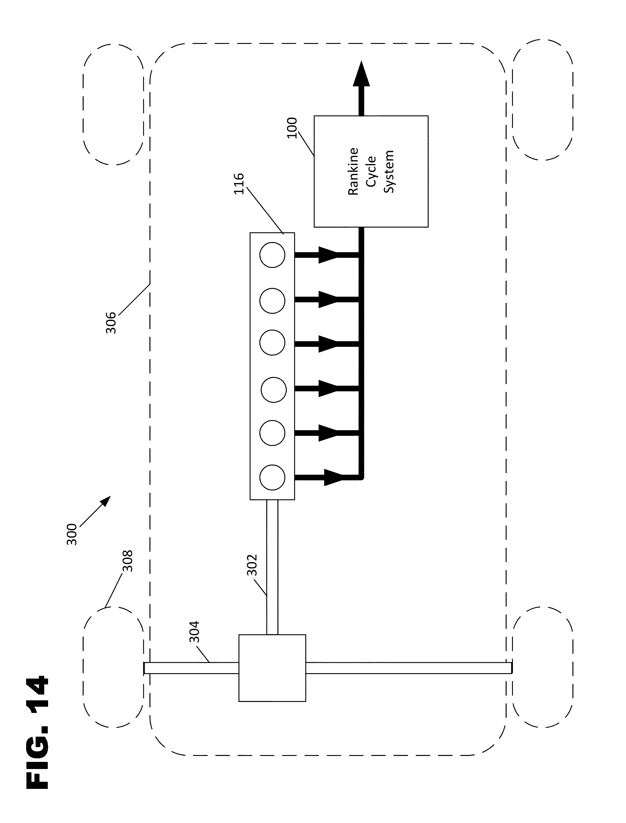
[0041] It will be appreciated that the engine 116 can be used to power a vehicle 300 (see FIG. 14). The vehicle 300 can include a torque transfer arrangement 302 (e.g., a drive train, drive shaft, transmission, differential, etc.) for transferring torque from the engine crankshaft to one or more axles 304 of the vehicle 300. The axles 304 can be coupled to wheels 308, or to tracks or other structures adapted to contact the ground. In such examples, the organic Rankine cycle system 100 and the engine 116 are carried with a vehicle chassis/frame 306 (shown schematically). In certain examples, prime movers such as fuel cells diesel engines or spark ignition engines can be used to power the vehicle.
Separator
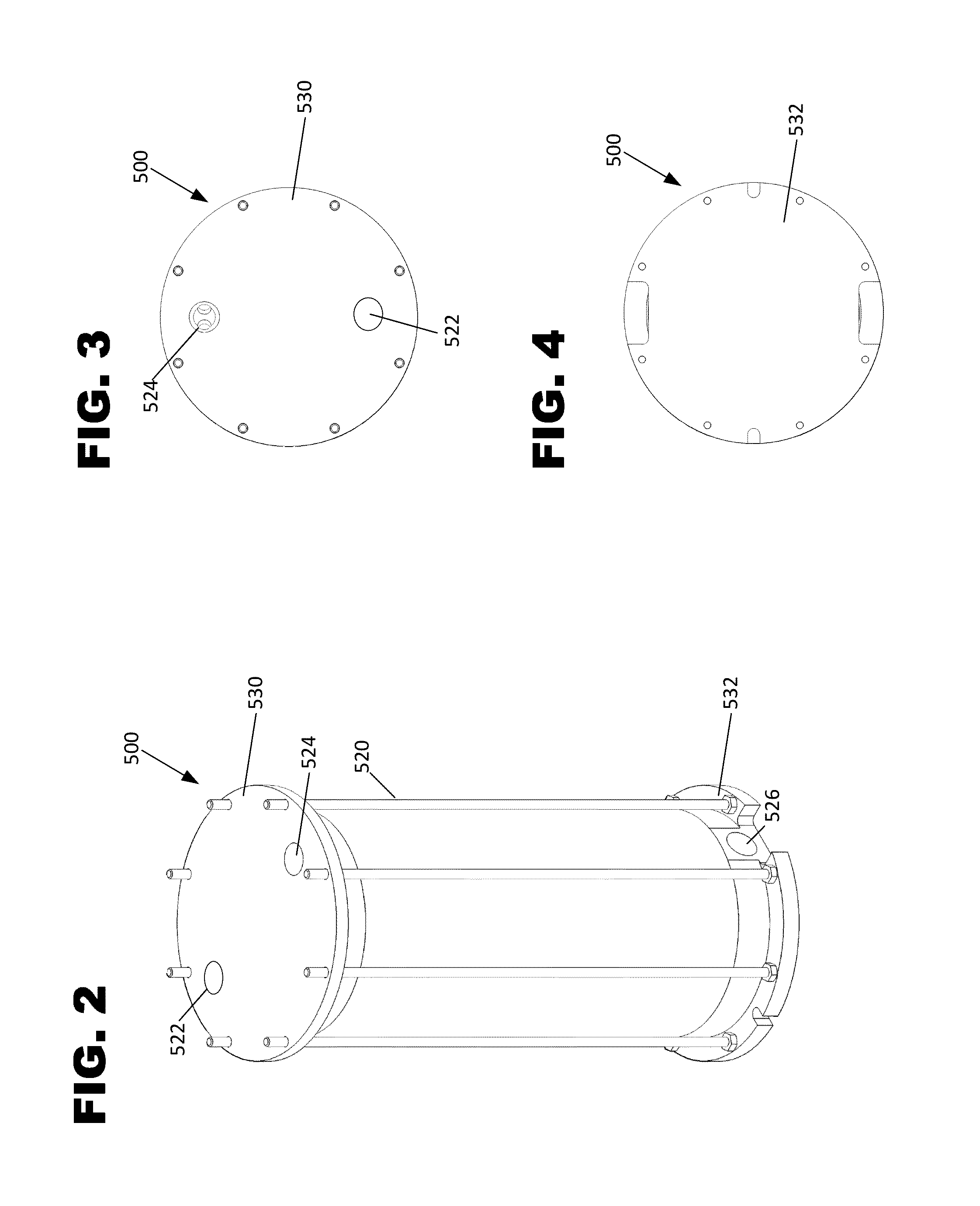
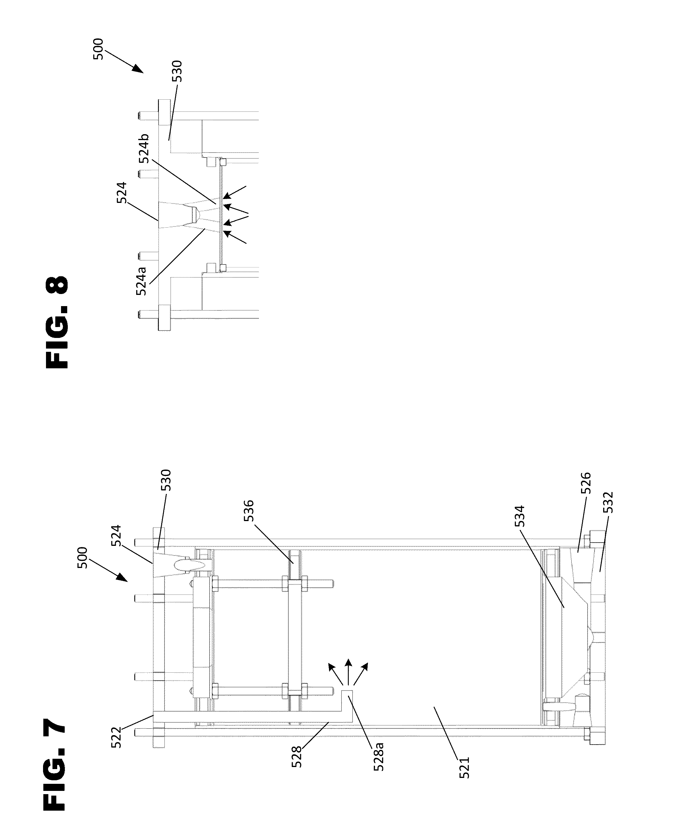
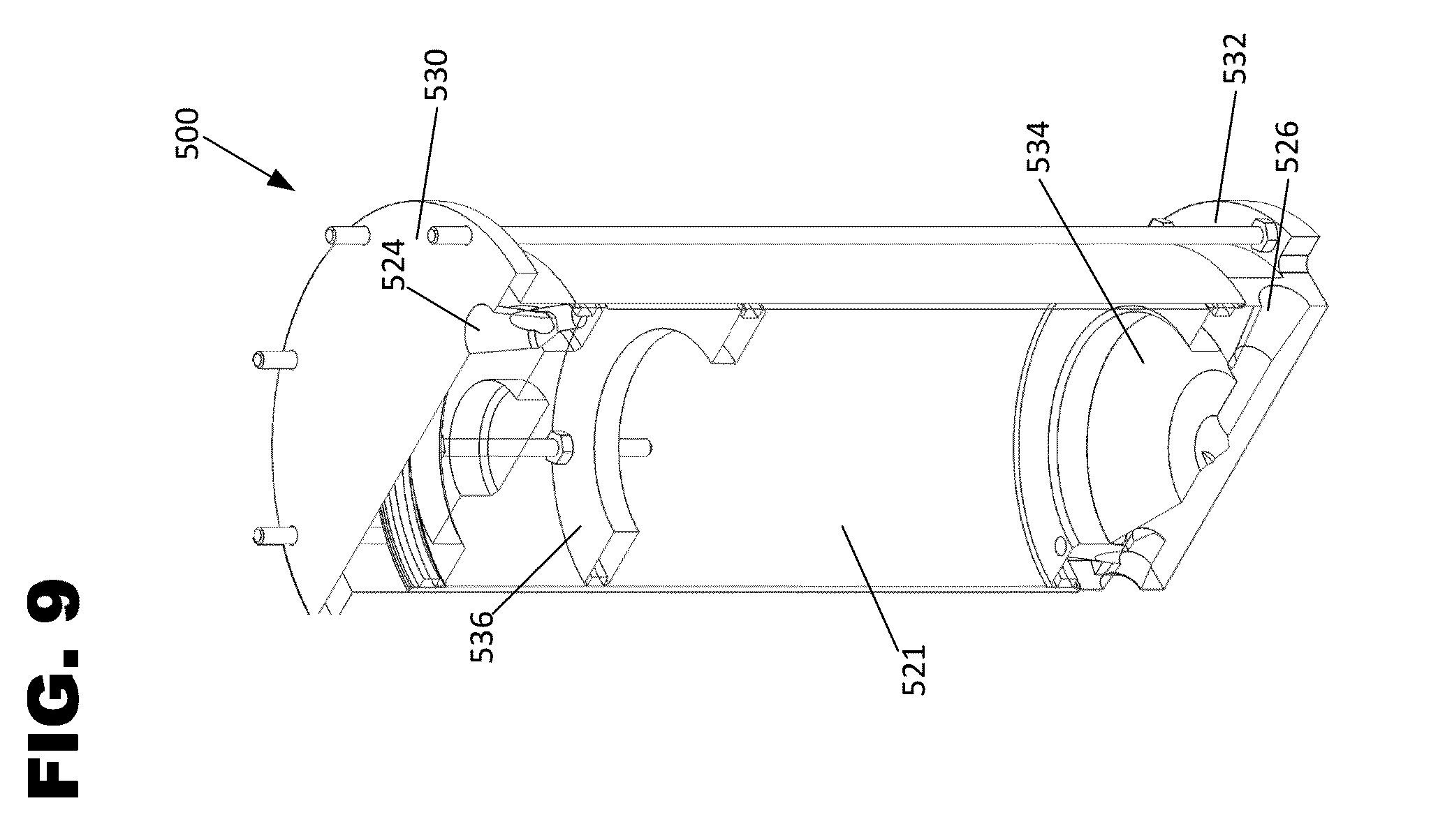
[0042] FIGS. 2-9 show an example separator 500 suitable for use as the separator 119 of the Rankine cycle systems of FIGS. 1 and 1A. The separator 500 includes a separator housing 520 defining an inlet 522, a first outlet 524, and a second outlet 526. As shown, the inlet 522 and first outlet 524 are located in a top plate 530 of the housing 520 while the second outlet 526 is located in a bottom plate 532 of the housing 520. When incorporated into the Rankine cycle system 100 of FIG. 1, the inlet 522 is coupled in fluid communication with the high pressure side of the pump 110 so as to receive the mixture of lubricant and Rankine cycle working fluid from the pump 110. Also, the first outlet 524 is coupled to the first non-shared segment 121 and the second outlet 526 is coupled to the second non-shared segment 123.
[0043] The separator inlet 522 can be provided with a conduit 528 that extends into the interior volume 521 of the separator 520 and directs the pumped fluid around the internal diameter of the separator to reduce the velocity of the mixture which accelerates the separation process. In one example, the conduit 528 is provided with a bent portion 528a for directing the fluid spray. The separator working fluid first outlet 524 can be provided with a plurality of converging inlet branches that extend from the outlet 524 into the interior volume 521 of the separator 500 to increase the velocity of the separated working fluid. As shown, two converging inlet branches 524a, 524b are provided. The separator lubricant second outlet 526 can be placed in fluid communication with the bottom of a funneled collection structure 534 which collects all lubricant to ensure that the outlet 526 is always subjected to a volume of lubricant. The separator 500 may also be provided with a diverter plate 536 within the interior volume 1 configured to minimize lubricant spray and to accelerate the separation process. In the example shown, the diverter plate 536 is provided with a toroid or doughnut shape with an open center. In one example, and as described in WO '156, the separator 500 can further include a filter or porous media to accelerate the separation process.
[0044] In this example, the mixture of lubricant (e.g., oil) and Rankine cycle working fluid (e.g., ethanol) can enter the oil separator 500 at the inlet 522 and flows into the interior volume 521 via conduit 528. In certain examples, the lubricant is heavier than the Rankine cycle working fluid and this weight difference allows the separator 500 to separate the lubricant from the Rankine cycle working fluid via gravity. For example within the housing 520, the lubricant sinks relative to the Rankine cycle working fluid. Thus, the Rankine cycle working fluid collects towards the top plate 530 of the housing 520 and the lubricant collects proximate the bottom plate 532 of the housing 520. The first outlet 524 is positioned at the top 528 of the housing 520 so as to receive the separated Rankine cycle working fluid while the second outlet 526 is positioned at a bottom 530 of the housing 520 so as to receive the separated lubricant. It is noted that the inlet and outlet positions can be relocated as necessary where the working fluid is more dense than the lubricant without departing from the concepts presented herein. The Rankine cycle working fluid exits the housing 520 through the first outlet 524 and flows through the first non-shared segment 121 to the heat exchanger 150. The lubricant exits the housing 520 through the second outlet 526 and flows through the second non-shared segment 123 to the lubricant containment structure 125 of the mechanical expander 127.
[0045] FIG. 2A shows a second embodiment of a separator 500 usable with either of the configurations shown in FIGS. 1 and 1A. In contrast to the separator 500 shown at FIGS. 2-9, the separator 500 of FIG. 2A is provided with a porous media 527 (e.g., a filtering media, a separating media, a precipitating media) contained within the housing 520 and is provided with a differently located inlet 522 and outlets 524, 526. The porous media 27 can include substance that contains pores or spaces between solid material through which liquid or gas can pass. Examples of naturally occurring porous media include sand, soil, and some types of stone, such as pumice and sandstone. Sponges, ceramics, and reticulated foam are also manufactured for use as porous media. It is to be understood that the type of porous media may vary with other examples. In some examples, the porous media can be made from wire mesh or knitted wire mesh, such as stainless steel wire mesh with a coiled construction, which is well suited for separating out the lubricating oil droplets. In one example, the density of the porous media can be on the order of about nine pounds per cubic foot. In other examples, the porous media can be made from a combined or co-knit metal wire and fiberglass mesh, such as a 304 stainless steel mesh co-knitted with fiberglass. These materials are found to be well-suited for filtering the lubricating oil and the porous media can have a density of about twelve pounds per cubic foot.
[0046] In the configuration shown at FIG. 2A, the mixture of lubricant (e.g., oil) and Rankine cycle working fluid (e.g., ethanol) can enter the oil separator 500 at the inlet 522 and flow through the porous media 527. The porous media 527 can slow the flow of the mixture, which encourages separation. In certain examples, the lubricant is heavier than the Rankine cycle working fluid and this weight difference allows the separator 500 to separate the lubricant from the Rankine cycle working fluid via gravity. For example within the housing 520, the lubricant sinks relative to the Rankine cycle working fluid. Thus, the Rankine cycle working fluid collects at a top 528 of the housing 520 and the lubricant collects at a bottom 530 of the housing 520. The first outlet 524 is positioned at the top 528 of the housing 520 so as to receive the separated Rankine cycle working fluid while the second outlet 526 is positioned at a bottom 530 of the housing 520 so as to receive the separated lubricant. The Rankine cycle working fluid exits the housing 520 through the first outlet 524 and flows through the first non-shared segment 121 to the heat exchanger 150. The lubricant exits the housing 520 through the second outlet 526 and flows through the second non-shared segment 123 to the lubricant containment structure 125 of the mechanical expander 127.
Mechanical Energy Extraction/Recovery Device
[0047] As described above, the organic Rankine cycle system 100 of FIGS. 1 and 1A includes a mechanical energy extraction zone 108 including at least one mechanical device (e.g., a reaction turbine, a piston engine, a scroll expander, a screw-type expander, a Roots expanders, etc.) capable of outputting mechanical energy from the Rankine cycle working circuit 102. In certain examples, the mechanical device relies upon the kinetic energy, temperature/heat and pressure of the working fluid to rotate the output shaft 400 (see FIG. 1). Where the mechanical device is used in an expansion application, such as with a Rankine cycle, energy is extracted from the working fluid via fluid expansion. In such instances, the mechanical device may be referred to as an expander or expansion device. However, it is to be understood that the mechanical device is not limited to applications where a working fluid is expanded across the device. In certain examples, the mechanical device includes one or more rotary elements (e.g., turbines, blades, rotors, etc.) that are rotated by the working fluid of the Rankine cycle so as to drive rotation of the output shaft 400 of the mechanical device. In certain examples, the output shaft 400 can be coupled to an alternator used to generate electricity, used to power active components, or used to charge a battery suitable for providing electrical power on demand. In other examples, the output shaft 400 can be coupled to a hydraulic pump used to generate hydraulic pressure, used to power active hydraulic components, or used to charge a hydraulic accumulator suitable for providing hydraulic pressure on demand. In still other examples, the output shaft 400 can be mechanically coupled (e.g., by gears, belts, chains or other structures) to other active components or back to a prime mover that is the source of waste heat for the Rankine cycle system.
[0048] In one example, the mechanical device used at the mechanical energy extracting zone 108 can include a Roots-style rotary device referred to herein as a Roots-style expander. Patent Cooperation Treaty patent application publication WO 2014/117159 discloses multi-stage expanders suitable for such use herein. The entirety of WO '159 is incorporated by reference herein. The pressure at the inlet side of the device is greater than the pressure at the outlet side of the device. The pressure drop between the inlet and outlet drives rotation within the device. Typically, except for decompression related to fluid leakage and device inefficiencies, expansion/decompression does not occur within the device itself, but instead occurs as the working fluid exits the device at the outlet. The device can be referred to a volumetric device since the device has a fixed displacement for each rotation of a rotor within the device.
[0049] As shown at FIG. 1, extraction device 127 includes a first stage 180, a second stage 182, and a third stage 184, wherein working fluid enters the inlet 117, then passes through the rotors of the first stage 180, then passes through the rotors of the second stage 182, and then passes through the rotors of the third stage 184 before existing through outlet 118. As there are gear sets and bearing points at the ends of each stage 180, 182, 184, lubrication containment chambers or structures 125a, 125b, 125c, and 125d are provided and placed in fluid communication with a lubrication fluid inlet 190. In one example, the chambers 125a-125d are placed in fluid communication with each other via an fluid delivery circuit 192 including internal and/or external branch lines, for example, branch line 192a, 192b, 192c, 192d, 192e, and 192f. To ensure that the appropriate lubricant flow reaches each of the chambers 125a-125d, flow control orifices may be provided in one or more of the individual branch lines 192a-192e. After passing through the chambers 125a-125d, the lubricant can be discharged through outlets in the device 127, for example, outlets 194, 196, and 198. As shown, outlets 194, 196, and 198 are placed in fluid communication with branch line 129. As outlets 194-198 are in close proximity to outlet 118, very little piping is required to reconnect the respective lines at primary mixing location 111. As stated previously, this approach minimizes costs and results in a more compact construction.
[0050] FIGS. 11-13 depict a generic, single stage Roots-style expander 200 also suitable for use at the mechanical energy extraction zone 108 of the Rankine cycle system 100. Expander 200 relies on the same general operating principles as extraction device 127 and the descriptions of each are therefore largely applicable for the other. The expander 200 includes a housing 202 having an inlet 204 and an outlet 206. In use, the inlet 204 is in fluid communication with the heating zone 106 of the Rankine cycle system 100 and the outlet 206 is in fluid communication with the condensing zone 104 of the Rankine cycle system 100.
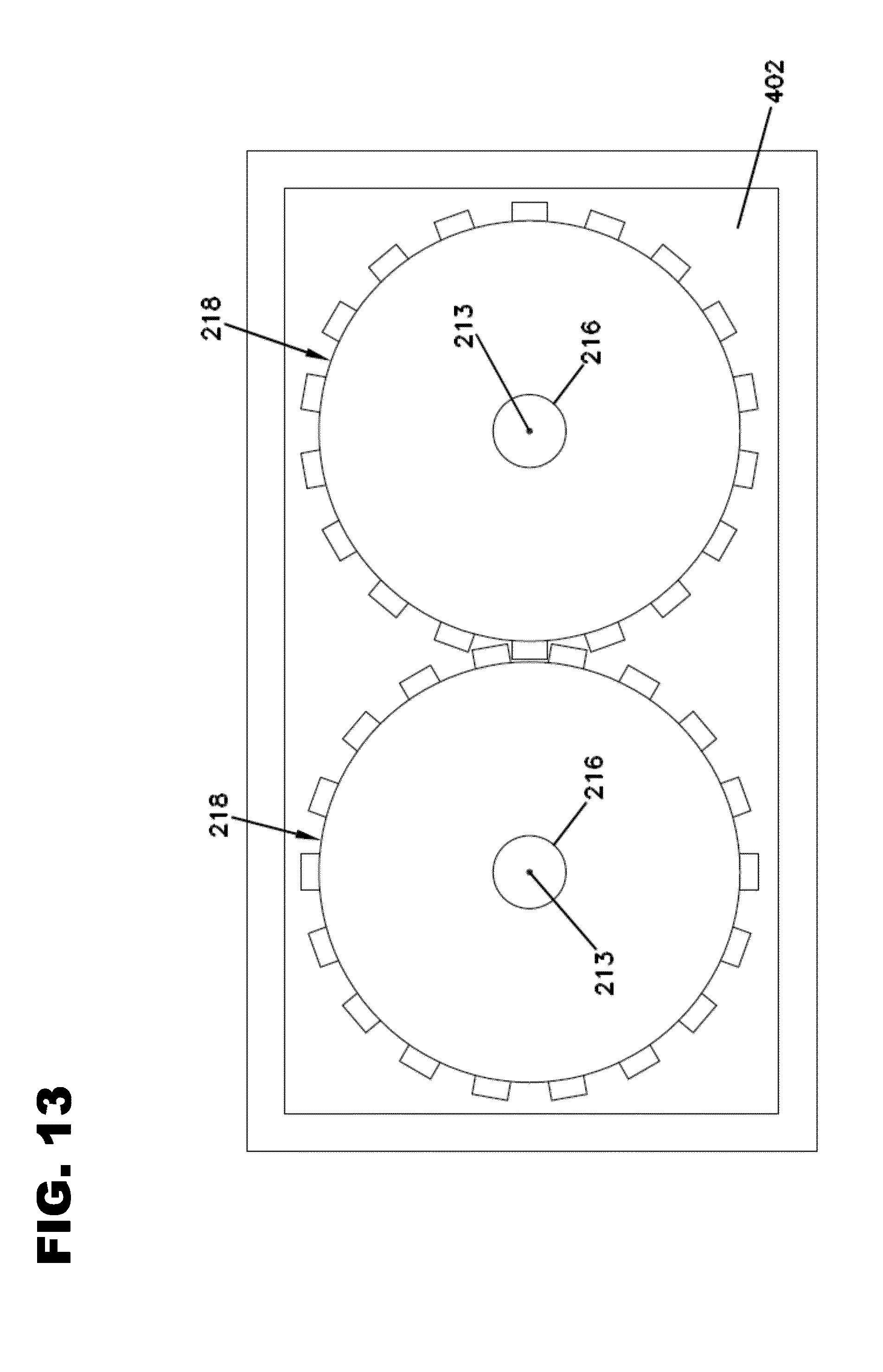
[0051] The expander housing 202 defines an internal cavity 208 (i.e., a rotor chamber) that provides fluid communication between the inlet 204 and the outlet 206. The internal cavity 208 is formed by first and second parallel rotor bores 210 (see FIG. 4) defined by cylindrical bore-defining surfaces 222. The expander 200 also includes first and second rotors 212 respectively mounted in the first and second rotor bores 210. Each of the rotors 212 includes a plurality of lobes 214 mounted on a shaft 216. The shafts 216 are parallel to one another and are rotatably mounted relative to the expander housing 202 by bearings 217 (FIG. 3). The shafts 216 are free to rotate relative to the housing 202 about parallel axes of rotation 213. The lobes 214 of the first and second rotors 212 intermesh/interleave with one another. Intermeshing timing gears 218 (see FIG. 5) are provided on the shafts 216 so as to synchronize the rotation of the first and second rotors 212 such that the lobes 214 of the first and second rotors 212 do not contact one another in use. In certain examples, the lobes 214 can be twisted or helically disposed along the lengths of the shafts 216. The rotors 212 define fluid transfer volumes 219 (FIG. 4) between the lobes 214. The lobes 214 can include outer tips 220 (FIG. 4) that pass in close proximity to the bore-defining surfaces 222 of the housing 202 as the rotors 212 rotate about their respective axes 213. In certain embodiments, the outer tips 220 do not contact the bore-defining surfaces 222.
[0052] In use of the expander 200, working fluid (e.g., vaporized working fluid or two-phase working fluid) from the heating zone 106 enters the expander housing 202 through the inlet 204. Upon passing through the inlet 204, the vaporized working fluid enters one of the fluid transfer volumes 219 defined between the lobes 214 of one of the rotors 212. The pressure differential across the expander 200 causes the working fluid to turn the rotor 212 about its axis of rotation 213 such that the fluid transfer volume 219 containing the vaporized working fluid moves circumferentially around the bore-defining surface 222 from the inlet 204 to the outlet 206. As the rotors 212 are rotated by the working fluid, mechanical energy is transferred out from the expander 200 through the output shaft 400 which coincides with one of the shafts 216. The output shaft 400 (FIG. 3) extends outwardly beyond an outer boundary of the expander housing 202 so as to be accessible for transferring torque/energy from the expander 200.
[0053] It will be appreciated that working fluid from the inlet 204 enters the internal cavity 208 of the housing 202 (see arrows 228 at FIG. 4) at a central region CR of the internal cavity 208 that is between parallel planes P, which include the axes 213 and which extend between inlet and outlet sides of the expander housing 202. The working fluid from the inlet 204 enters fluid transfer volumes 219 of the rotors 212 at the central region CR and causes the rotors 212 to rotate in opposite directions about their respective axes 213. The rotors 212 are rotated about their respective axes 213 such that the fluid transfer volumes 219 containing the working fluid move away from the central region CR along their respective circumferential bore-defining surface 222 of the housing 202 to outer regions OR (i.e., regions outside the planes P) of the internal cavity 208 as indicated by arrows 230 (see FIG. 4). The rotors 212 continue to rotate about their respective axes 213 thereby moving the fluid transfer volumes 219 from the outer regions OR back to the central region CR adjacent the outlet 206 as indicated by arrows 232. The working fluid from the fluid transfer volumes 219 exits the expander housing 202 through the outlet 206 as indicated by arrows 234 (see FIG. 4).
[0054] The intermeshing gears 218 and bearings 217 can be positioned within a lubrication chamber 402 containing lubricant for lubricating the gears 218 and the bearings 217 (see FIG. 3). The lubrication chamber 402 is an example of the lubricant containing structure 125 of FIG. 1. The temperature in the rotor cavity can be as high as 300.degree. C. to 350.degree. C. and thus bearings and timing gears in the expander are exposed to relatively high temperatures. The high temperature can deteriorate the lubricating oil for the bearings and timing gears and reduce the life of the bearings and timing gears. To prevent this from occurring, the lubrication circuit 113 can be used to circulate the lubricant through the lubrication chamber 402 so the lubricant is exposed to the high temperatures for only a limited amount of time. The lubricant of the lubrication circuit 113 is cooled by the Rankine cycle working fluid as both fluids pass through the condenser 170. In the circuit shown at FIG. 1A, the lubricant is cooled when the lubricant mixes with the relatively cool Ranking cycle working fluid that exits the condensing zone 104. Inside the condenser 170, the Rankine cycle working fluid condenses and cools as it undergoes a phase change within the condensing zone 104. The condensed Rankine cycle working fluid is then able to absorb heat from the lubricant. It will be appreciated that the lubrication chamber 402 is one example of a lubricant containment structure 125 and that other lubricant containing structures 125 (e.g., other lubricant chambers) can also be provided as part of the lubrication circuit 113.
Rankine Cycle Operation
[0055] FIG. 2 shows a general diagram depicting a representative Rankine cycle applicable to the system 100, as described with respect to FIGS. 1 and 1A. The diagram depicts different stages of the Rankine cycle showing temperature in Celsius plotted against entropy "S", wherein entropy is defined as energy in kilojoules divided by temperature in Kelvin and further divided by a kilogram of mass (kJ/kg*K). The Rankine cycle shown in FIG. 2 is specifically a closed-loop Organic Rankine Cycle (ORC) that may use an organic, high molecular mass working fluid with a liquid-vapor phase change or boiling point occurring at a lower temperature than the water-steam phase change of the classical Rankine cycle. Accordingly, in the system 100, the working fluid may be a solvent, such as ethanol, n-pentane or toluene.
[0056] In the diagram of FIG. 2, the term "Q" represents the heat flow to or from the system 100, and is typically expressed in energy per unit time. The term "W" represents mechanical power consumed by or provided to the system 100, and is also typically expressed in energy per unit time. As may be additionally seen from FIG. 2, there are four distinct processes or stages 142-1, 142-2, 142-3, and 142-4 in the ORC. During stage 142-1, the Rankine cycle working fluid in the form of a wet vapor enters and passes through at least one condenser 170 at the condensing zone 104, in which the Rankine cycle working fluid is condensed at a constant temperature to become a saturated liquid. Following stage 142-1, the Rankine cycle working fluid is pumped from low to high pressure by the pump 106 during the stage 142-2. During stage 142-2, the Rankine cycle working fluid is in a liquid state.
[0057] From stage 142-2 the Rankine cycle working fluid is transferred to stage 142-3. During stage 142-3, the pressurized Rankine cycle working fluid enters and passes through the heat exchanger 150 where it is heated at constant pressure by an external heat source to become a vapor or a two-phase fluid, (i.e., liquid together with vapor). During stage 142-4, the Rankine cycle working fluid, in the form of a fully vaporized fluid or a two-phase fluid, passes through the mechanical energy extracting zone 108, thereby generating useful work or power. The working fluid may expand at the outlet of the mechanical energy extracting zone 108 thereby decreasing the temperature and pressure of the working fluid such that some additional condensation of the working fluid may occur. Following stage 142-4, the working fluid is returned to the condensing zone 104, at which point the cycle completes and will typically restart at stage 142-1.
[0058] From the forgoing detailed description, it will be evident that modifications and variations can be made without departing from the spirit and scope of the disclosure.
* * * * *
D00000
D00001
D00002
D00003
D00004
D00005
D00006
D00007
D00008
D00009
D00010
D00011
D00012
XML
uspto.report is an independent third-party trademark research tool that is not affiliated, endorsed, or sponsored by the United States Patent and Trademark Office (USPTO) or any other governmental organization. The information provided by uspto.report is based on publicly available data at the time of writing and is intended for informational purposes only.
While we strive to provide accurate and up-to-date information, we do not guarantee the accuracy, completeness, reliability, or suitability of the information displayed on this site. The use of this site is at your own risk. Any reliance you place on such information is therefore strictly at your own risk.
All official trademark data, including owner information, should be verified by visiting the official USPTO website at www.uspto.gov. This site is not intended to replace professional legal advice and should not be used as a substitute for consulting with a legal professional who is knowledgeable about trademark law.