Dual Bearing Rotating Control Head And Method
Lock; Jason Philip
U.S. patent application number 14/766576 was filed with the patent office on 2015-12-31 for dual bearing rotating control head and method. The applicant listed for this patent is SMITH INTERNATIONAL, INC.. Invention is credited to Jason Philip Lock.
| Application Number | 20150376972 14/766576 |
| Document ID | / |
| Family ID | 51300280 |
| Filed Date | 2015-12-31 |


| United States Patent Application | 20150376972 |
| Kind Code | A1 |
| Lock; Jason Philip | December 31, 2015 |
DUAL BEARING ROTATING CONTROL HEAD AND METHOD
Abstract
An apparatus comprises a first bearing assembly, a second bearing assembly, a housing and a pipe. The first bearing assembly, the second bearing assembly and the housing define an interior space. The pipe extends through the first bearing assembly and the second bearing assembly and through the interior space.
| Inventors: | Lock; Jason Philip; (Red Deer, Alberta, CA) | ||||||||||
| Applicant: |
|
||||||||||
|---|---|---|---|---|---|---|---|---|---|---|---|
| Family ID: | 51300280 | ||||||||||
| Appl. No.: | 14/766576 | ||||||||||
| Filed: | February 11, 2014 | ||||||||||
| PCT Filed: | February 11, 2014 | ||||||||||
| PCT NO: | PCT/US2014/015709 | ||||||||||
| 371 Date: | August 7, 2015 |
Related U.S. Patent Documents
| Application Number | Filing Date | Patent Number | ||
|---|---|---|---|---|
| 61762989 | Feb 11, 2013 | |||
| Current U.S. Class: | 166/250.08 ; 166/381; 166/84.3 |
| Current CPC Class: | E21B 33/085 20130101; E21B 19/00 20130101; E21B 33/06 20130101; E21B 21/08 20130101; E21B 47/06 20130101 |
| International Class: | E21B 33/06 20060101 E21B033/06; E21B 21/08 20060101 E21B021/08; E21B 47/06 20060101 E21B047/06; E21B 19/00 20060101 E21B019/00 |
Claims
1. An apparatus comprising: a first bearing assembly; a second bearing assembly; a housing, the first bearing assembly, the second bearing assembly and the housing defining an interior space, and a pipe extending through the first bearing assembly and the second bearing assembly and through the interior space.
2. The apparatus of claim 1, wherein the housing comprises at least one port in fluid communication with the interior space.
3. The apparatus of claim 2, further comprising a main pressure sensor in fluid communication with the interior space.
4. The apparatus of claim 2, further comprising a fluid pump in fluid communication with the interior space.
5. The apparatus of claim 4, further comprising a pressure regulator in fluid communication with the interior space.
6. The apparatus of claim 5, wherein the fluid pump moves a lubricant.
7. The apparatus of claim 1, further comprising a first pressure sensor located exteriorly of the interior space functionally adjacent the first bearing assembly.
8. The apparatus of claim 1, further comprising a second pressure sensor exteriorly of the interior space adjacent the second bearing assembly.
9. The apparatus of claim 1, wherein each of the first bearing assembly and the second bearing assembly comprises a stripper element, the pipe to be accommodated by the stripper elements.
10. The apparatus of claim 1, wherein the apparatus comprises a rotating control head.
11. A method comprising: pressurizing fluid to a predetermined value in an interior space defined by a housing, a first bearing assembly and a second bearing assembly; and measuring a pressure of the interior space to determine a leak in at least one of the first bearing assembly and the second bearing assembly when the measured pressure differs from the predetermined by a predetermined amount.
12. The method of claim 11, further comprising measuring a pressure from a first pressure sensor located exteriorly of the interior space and adjacent the first bearing assembly to determine a leak in the first bearing assembly.
13. The method of claim 11, further comprising measuring a pressure from a second pressure sensor located exteriorly of the interior space and adjacent the second bearing assembly to determine a leak in the second bearing assembly.
14. The method of claim 11, wherein the fluid comprises a lubricant.
15. The method of claim 11, further comprising replacing at least one of the first bearing assembly and the second bearing assembly.
16. A method comprising: pumping lubricant into an interior space of an apparatus defined by at least a first bearing assembly and a second bearing assembly, each of the first bearing assembly and the second bearing assembly comprising a stripper element; and inserting a pipe through the interior space so as to go through the first bearing assembly and the second bearing assembly.
17. The method of claim 16, further comprising moving the pipe with respect to the interior space so as to lubricate at least one stripper element.
18. The method of claim 17, wherein moving the pipe in a first direction introduces the lubricant to the stripper element associated with the first bearing assembly.
19. The method of claim 17, wherein moving the pipe in a second direction introduces the lubricant to the stripper element associated with the second bearing assembly.
20. The method of claim 17, wherein the pumping generates a pressure substantially equal to a pressure in an annular space in a wellbore.
Description
STATEMENT REGARDING FEDERALLY SPONSORED RESEARCH OR DEVELOPMENT
[0001] Not applicable.
BACKGROUND
[0002] This disclosure relates generally to the field of wellbore pressure control devices. More specifically, the disclosure relates to pressure control devices that control and diver drilling and wellbore fluids while providing a seal around a tubular component.
[0003] Wellbore pressure control devices include devices known as rotating control heads, rotating diverters, rotating blowout preventers (hereinafter rotating control head or "RCH"). Such pressure control devices are configured to enable a string of pipe and/or wellbore drilling or intervention tools to sealingly pass therethrough axially, and further to enable rotation of the pipe while sealing the wellbore hydraulically. When used, for example in wellbore drilling operations, a drill pipe string is passed through a bearing assembly in the RCH. The bearing assembly enables a seal element therein and the pipe to rotate relative to a housing that may be affixed to the top of a casing or other pipe disposed at least partially into the wellbore. The housing is configured to enable hydraulic communication to the interior of the wellbore below the bearing assembly. One non-limiting use for RCHs may be in managed pressure drilling.
[0004] When bearings in the bearing assembly fail, expensive and difficult procedures to remove the pipe from the wellbore are conducted while maintaining the wellbore hydraulic seal through the RCH. Also, difficult and expensive pipe removal operations are conducted because seal elements in the bearing assembly fail.
BRIEF DESCRIPTION OF THE DRAWINGS
[0005] FIG. 1 is a schematic view of a pipe being inserted into a wellbore through a rotating control head (RCH);
[0006] FIG. 2 is a first side view of an example RCH according to the present disclosure;
[0007] FIG. 3 is a cut away view of the RCH shown in FIG. 1;
[0008] FIG. 4 is a second side view of the assembled RCH shown in FIG. 3; and
[0009] FIG. 5 is a cut away view of the RCH shown in FIG. 4.
DETAILED DESCRIPTION
[0010] An example wellbore operation in which a rotating control head (RCH) may be used is shown schematically in FIG. 1. A wellbore 12 may be drilled into subsurface Earth formations 13 to a selected depth. A pipe 14, for example, a drill pipe or drill string may include one or more structures 10, such as centralizers, stabilizers or other drilling tools that have a diameter larger than the nominal outer diameter (diameter) of the pipe 14. The pipe 14 may be lowered into the wellbore 12 by a hoisting system such as a drilling rig 16 or the like. The drilling rig 16 may include a drawworks 20 or similar hoisting apparatus that extends and retracts a drill line 21. Movement of the drill line 21 cooperates with sheaves or "blocks" 18 to cause upward and downward motion of a top drive 22 or similar device to enable rotational motion of the pipe 14.
[0011] Typically, during operations, the wellbore 12 is filled with fluid 11, such a "drilling mud", a completion brine or other fluid used to drill and/or complete the wellbore 12. The fluid 11 is typically lifted from a pit or tank 26 disposed at the surface. The tank 26 may include a supply of cleaned or conditioned fluid 28. The fluid 28 may be lifted by a pump 24 which discharges the fluid to the top drive 22. Internal rotating seal elements in the top drive 22 enable the fluid 28 to be pumped through the interior of the pipe 14 into the wellbore 12. The top drive 22 may also be used to rotate the pipe 14, such as for axially lengthening (drilling) the wellbore 12.
[0012] The wellbore 12 may include a pipe or casing 33 ("surface casing") set to a relatively limited depth near the surface. An upper end of the surface casing 33 may be coupled to a sealing element called a rotating control head 34. The rotating control head 34 may be coupled to the casing by a flange 34B to a corresponding flange 33A at the upper end of the surface casing 33, although the manner of coupling the rotating control head 34 to the surface casing 33 is not a limitation on the scope of the present disclosure.
[0013] The rotating control head 34 seals an annular space 12A between the exterior of the pipe 14 and the interior of the surface casing 33 to prevent uncontrolled release of fluid 11 from the wellbore 12. The rotating control head 34 may include a fluid discharge outlet 34A. The fluid discharge outlet 34A may be disposed below sealing elements (FIGS. 2 and 3) in the rotating control head 34 to enable flow of the fluid 11 out of the annular space 12A. The fluid outlet 34A may be coupled through a controllable choke 32 or similar variable restriction flow control device that ultimately may return the fluid 11 to the tank 26. In some examples, the fluid discharge outlet 34A may include a pump 30 coupled thereto at its discharge side so that fluid pressure in the wellbore 12 outside the pipe 14 may be maintained at a selected level. The pressure of fluid being discharged from the annular space 12A may be measured using a pressure sensor 127C in fluid communication with the fluid discharge outlet 34A.
[0014] The example shown in FIG. 1 has a pipe 14 in the form of a drill string being inserted into the wellbore 12. It should be clearly understood that the rotating control head 34 of the present disclosure is equally applicable to any type of pipe being inserted into a wellbore, including as non-limiting examples casing, liner, coiled tubing, production tubing and rod strings. Accordingly, a rotating control head according to the present disclosure is not limited in scope to being used with a drill string. If the pipe 14 is a casing or liner, the structures 10 may be centralizers affixed to the exterior of the pipe 14 to provide force to urge the pipe 14 toward the center of the wellbore 12 when inserted therein. A possible advantage of the rotating control head 34 of the present disclosure when structures are used on the pipe 14 having a larger diameter than the nominal outer diameter of the pipe 14 will be further explained below.
[0015] In an example dual bearing assembly rotating control head according to the present disclosure, and as will be explained further below, two independent bearing assemblies, each having a sealing or stripper element associated therewith, may be assembled to a rotating control head housing in tandem and connected to each other in spaced apart relation by a housing such as a spacer spool. A first bearing assembly may be configured to support most of the operating load of wellbore operations. As the first bearing assembly reaches the end of its operable life, whether by impending failure of the bearing and/or the sealing element, a second bearing assembly may enable continuing wellbore operations to a point where the ordinary sequence of wellbore operations would allow for a bearing assembly to be replaced without unduly interrupting wellbore operations.
[0016] In the present example, and as will be further explained below with reference to FIGS. 2 and 3, the bearing assemblies may be connected to each other and longitudinally spaced apart by a housing such as a "spacer spool" and clamping system. A first bearing assembly 118 may bolt to or otherwise be affixed to the bottom of the interior of a main rotating control head housing that is affixable to the wellbore pipe or surface casing (33 in FIG. 1), or, for example, to a drilling riser when the rotating control head is used in marine drilling operations. A second bearing assembly 110 may be affixed in place on the upper end of the housing or spacer spool using fasteners similar to those used in conventional rotating control heads, for example, band-type clamps or threaded rings. The entire dual bearing system may then clamp onto the main rotating control head housing using, for example, a single band type clamp or other type of fastener, e.g., mating flanges with an internal o-ring seal. As will be further explained, the spacer spool may have an interior space between the bearing assemblies that is in fluid communication with a port in the spacer spool. Such port may be used, for example, for measurement of pressure and/or introduction of fluid into the interior space in the spacer spool.
[0017] The first bearing assembly 118 as well as the second bearing assembly 110 may require additional seals within a bearing pack, sufficiently strong to control the intended maximum operating pressures (e.g., 3000 pounds per square inch static) in the wellbore (12 in FIG. 1). The bearing pack and associated seals will be explained below with reference to FIG. 3. The spacer spool 114 may allow the first and second bearing assemblies 118, 110 to operate independently. With suitably selected longitudinal spacing between the first and second bearing assemblies 118, 110, such as may be obtained by suitable selection of the length of the spacer spool 114, the housing or spacer spool 114 may enable a continuously engaged seal around at least part of a nominal outer diameter portion of the pipe (e.g., 14 in FIG. 1) when through-passing larger diameter pipe elements, such as casing collars or drill pipe tool joints are used with such pipe (14 in FIG. 1) thus limiting possible fluid bypass from the annular space (12A in FIG. 1) when stripping operations (i.e., longitudinal movements of the pipe 14 in FIG. 1) occur.
[0018] The example first and second bearing assemblies 118, 110 may be stabbed onto a pipe (e.g., the pipe 14 in FIG. 1), positioned within the rotating control head housing and the spacer spool 114, respectively, retained in place and the interior space in the spacer spool 114 between the two bearing assemblies 118, 110 may subsequently be filled with a fluid medium, e.g., lubricant, and pressurized to a predetermined pressure. Such pressure may be a equal to or above anticipated operating pressures in the wellbore (12 in FIG. 1) in some implementations. By measuring pressure within the spacer spool 114, the wellbore operator may be able to detect pressure anomalies both within the spacer spool 114 and the bearing assemblies 118, 110. For example, a measured pressure spike or loss within the spacer spool 114 may indicate first bearing assembly 118 leakage or proximate failure. The foregoing may enable the wellbore operator sufficient warning to allow determining a timeline of the anticipated life expectancy of the second bearing assembly 110, thus enabling the wellbore operator to plan a bearing assembly change at a point within the wellbore operations that minimizes disruption of the ordinary course of such operations.
[0019] A side view of an assembled dual bearing assembly rotating control head 34 according to the present disclosure is shown in FIG. 2. A second bearing assembly 110 may be retained in place within an upper end of a second housing, hereinafter referred to as a "spacer spool" 114 by a band clamp 112 or other retaining element known in the art.
[0020] The spacer spool 114 may include one or more ports 114A, terminated with couplings such as flanges or other pressure tight coupling features. The one or more ports 114A may be in fluid communication with an interior space (114B in FIG. 3) in the spacer spool 114. The interior space 114B may enable fluid introduced therein to contact both bearing assemblies 118, 110 (explained further below). By providing one or more ports 114A, it may be possible to measure pressure within the spacer spool 114, and/or to pump fluids into the spacer spool 114. Measuring pressure may be performed by having a main pressure sensor 127 in fluid communication with one of the ports 114A. Measuring pressure using the main pressure sensor 127 is functionally equivalent to measuring pressure proximate the first bearing assembly 118 outside the interior space (114B in FIG. 3). It may be possible, for example, to pump fluid such as a lubricant (e.g., lubricating oil) into the spacer spool 114 through the one or more ports 114A to clean and lubricate, and thus possibly extend the operating lifetime of a first bearing assembly (see 118 in FIG. 3) and/or the second bearing assembly 110. In one example, a fluid pump 129 may be in fluid communication with the one or more ports 114A to enable such pumping. The pressure applied by the pump 129 may be maintained at any selected value by a pressure regulator 127A coupled to either of the ports 114A. In another example, the pump 129 may be used to pump fluid into the interior of the spacer spool, e.g., through one of the ports 114A so that the rotating control head (34 in FIG. 1) may be tested for any leakage. Such pressure testing may require insertion of a pipe (e.g., 14 in FIG. 1) through the first and second bearing assemblies (110 and 118, respectively, in FIG. 3) to close a passage (explained below) provided through the first and second bearing assemblies.
[0021] The first bearing assembly (118 in FIG. 3) may be retained in place in a main rotating control head housing 124 using a flange-type bearing retainer 123. The flange type bearing retainer 123 may be affixed to a first housing, hereinafter referred to as the "main rotating control head housing" 124 using a band clamp 120 or any other coupling device. The flange type bearing retainer 123 may be coupled to a mating flange 121 on the spacer spool 114 using studs and nuts, shown generally at 125, such studs and nuts being of types known in the art for affixing mating flanges in a flange coupling together.
[0022] The main rotating control head housing 124 may couple to the wellbore pipe or casing (33 in FIG. 1) using a fluid pressure tight connector of any type known in the art, for example a flange 34B as shown in FIG. 2. The example flange 34B shown in FIG. 2 is not intended to limit the scope of what may be used to couple the main rotating control head housing 124 to the wellbore pipe (33 in FIG. 1).
[0023] The fluid discharge port 34A explained with reference to FIG. 1 is shown in FIG. 2 in a convenient position in the main rotating control head housing 124. The use of band clamps as shown in FIG. 2 is not intended to limit the scope of means by which the main rotating control head housing 124 and the first bearing assembly (118 in FIG. 3) are respectively coupled. Likewise, using a band type clamp 112 to couple the second bearing assembly 110 to the spacer spool 114 is only provided as an example and is not intended to limit the means by which the second bearing assembly 110 may be affixed to the spacer spool 114.
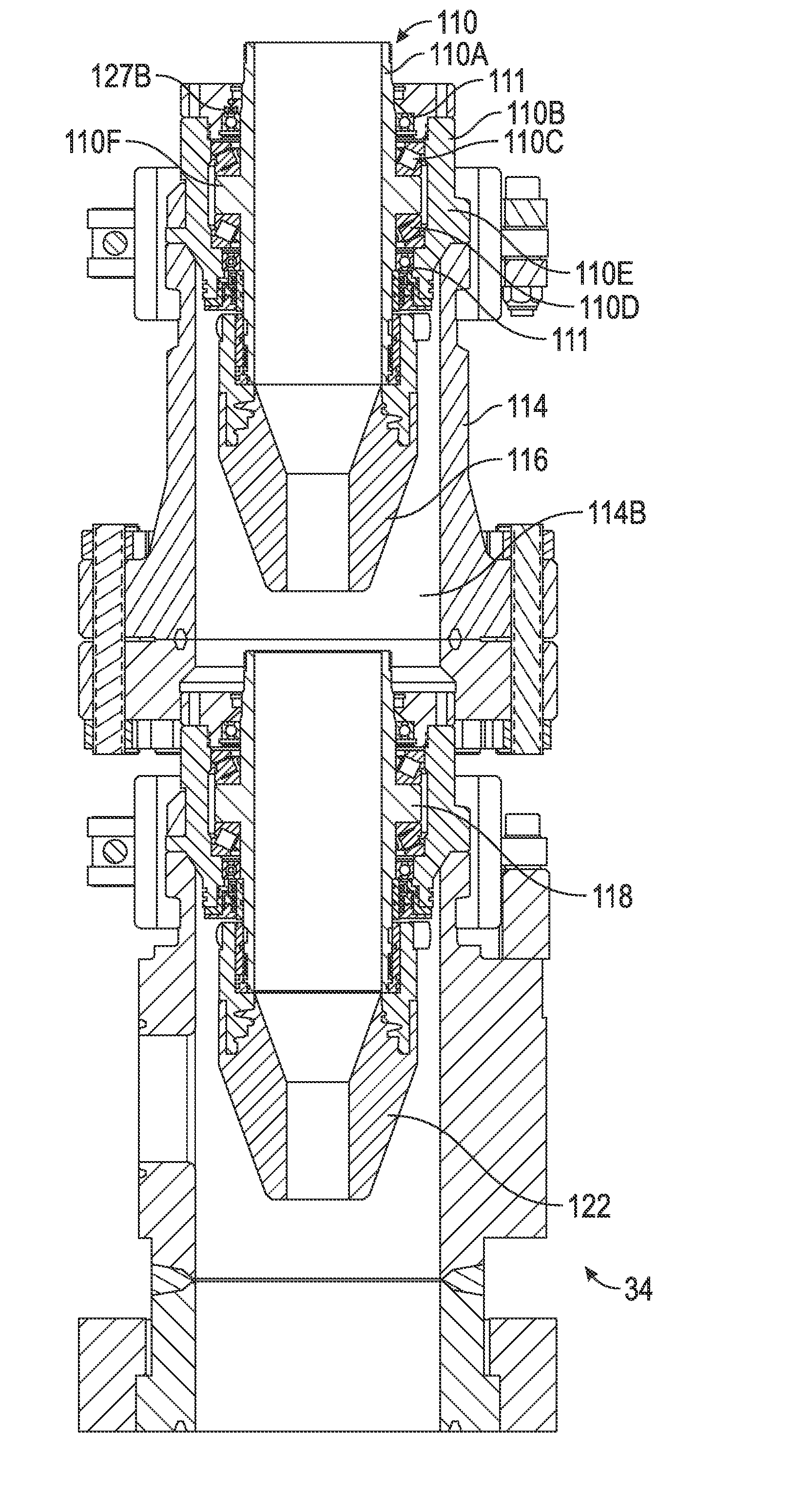
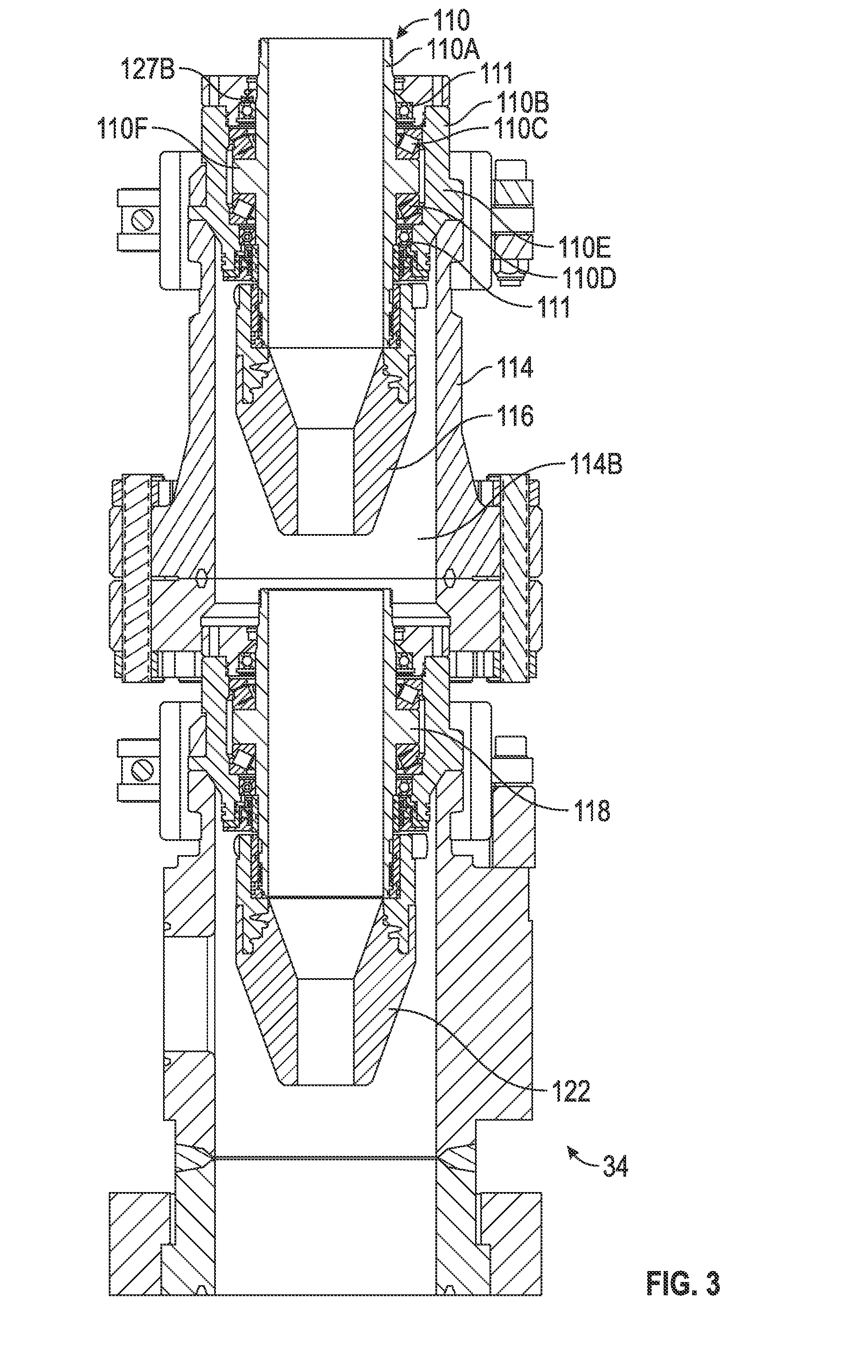
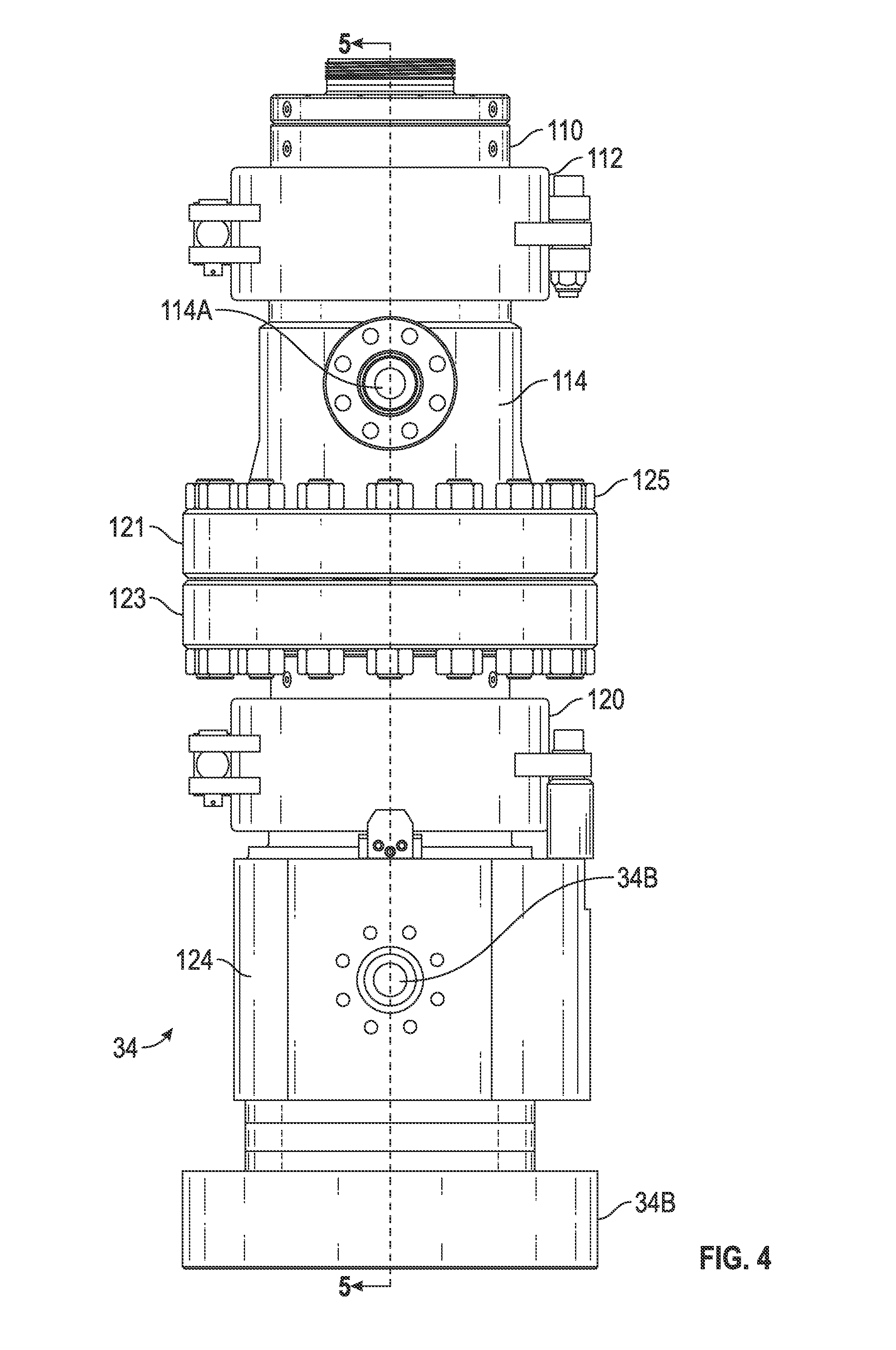
[0024] Some of the details of the first and second bearing assemblies will now be explained with reference to FIGS. 3-5. FIG. 4 shows a view of the rotating control head shown in FIG. 2 rotated 90 degrees. The view of FIG. 4 more clearly shows the one or more ports 114A in the spacer spool. In the example shown in FIG. 4, the main rotating control head housing 124 may include an additional fluid discharge port 34B, which is in hydraulic communication with the interior of the main rotating control head housing 124. FIG. 5 shows a cross-sectional view of the view shown in FIG. 4. The ports 114A are visible as being in fluid communication with the interior of the spacer spool 114. The two fluid discharge ports 34A, 34B in the main rotating control head housing 124 are also observable as being in fluid communication with the interior of the main rotating control head housing 124 below the first stripper element (122 in FIG. 3).
[0025] Each of the first 118 and second bearing 110 and assemblies may include a respective stripper element 122, 116 to provide sealing engagement to a pipe or pipe string moved longitudinally through each bearing assembly 118, 110, respectively, e.g., the pipe 14 as shown in FIG. 1. With reference to the second bearing assembly 110, such assembly may include a sleeve 110A for engaging and/or guiding the pipe (14 in FIG. 1) as it is moved longitudinally through the second bearing assembly 110. The stripper element 116 may be affixed to a lower end of the sleeve 110A so that pipe moved through the sleeve 110A has a pressure tight seal to substantially prevent escape of fluid from within the interior space 114B in the spacer spool 114.
[0026] The sleeve 110A may include a shoulder 110F on an exterior thereof. The shoulder 110F may be in contact with an upper bearing 110C and a lower bearing 110D each on one side of the shoulder 110F. The upper bearing 110C and the lower bearing 110D may rotatably transfer axial loading from the sleeve 110A to a bearing housing 110E. The bearing housing 110E may be the portion of the second bearing assembly that is coupled to the spacer spool 114. The upper bearing 110C and the lower bearing 110D may each be sealed with respective seals 111 of any type known in the art to seal a rotating shaft passing through a bearing supporting such shaft rotatably in a fixed housing.
[0027] The first bearing assembly 118 may be mounted in the main rotating control head housing 124 as explained above, and may have substantially the same components, including a sleeve and stripper element 122 as explained with reference to the second bearing assembly 110.
[0028] An additional pressure sensor 127B may be disposed in a chamber therefor located above the upper seal 111. In the event any fluid leaks past the second bearing assembly 110, suck leakage may be detected by an increase in the pressure measured by the additional pressure sensor 127B. By using measurements of pressure from the pressure sensor (127 in FIG. 2) in communication with one of the ports (114A in FIG. 2) and the additional pressure sensor 127A, it may be possible to identify which of the first and second bearing assemblies and associated stripper elements may be leaking.
[0029] As explained above, by having at least one port (114A in FIG. 2) in fluid communication with an interior 114B of the spacer spool 114, it may be possible to measure pressure inside the spacer spool 114. Thus, indications of any fluid leakage from the wellbore (12 in FIG. 1) through the first bearing assembly 118 and/or the second 110 bearing assembly may be observed. In one example, if the measured pressure inside the spacer spool 114 deviates from a setpoint or predetermined pressure (such as may be applied by the pump 129 in FIG. 2) by a predetermined amount, an indication of leakage in the first bearing assembly and/or its associated stripper element may be inferred. In one example, depending on a pressure in the wellbore (12 in FIG. 1), an increase in measured pressure in the spacer spool 114 may indicate the stripper element 122 in the first bearing assembly 118 is leaking. In another example, a reduction in pressure measured in the spacer spool 114 may indicate that the striper element 116 in the second bearing assembly 110 is leaking. In addition, measurements of pressure using the additional pressure sensor may indicate leakage of the seal and bearing pack associated with the second bearing assembly 110.
[0030] One or more of such indications based on measured pressure may provide the wellbore operator an indication that the first bearing assembly requires removal and replacement. In some examples, such removal and replacement may be performed at a time during wellbore operations so as to minimize disruption of such operations. One specific example may be during a time in which the entire pipe is removed from the wellbore to change a drill bit. During the time in which wellbore operations continue even with failure of the stripper element 122 in the first bearing assembly 118, the stripper element 116 in the second bearing assembly 110 may prevent fluid from bypassing the rotating control head 34, thus providing the wellbore operator with a possible opportunity to continue wellbore operations uninterrupted until a convenient time is available for bearing assembly replacement. The foregoing continuation of wellbore operations may be based on an estimated remaining lifetime of the second bearing assembly and/or the stripper element associated therewith. Provided that the estimated remaining lifetime is at least or exceeds an expected time until the convenient time, wellbore operations may continue until the convenient time, whereupon the first and/or second bearing assemblies may be replaced.
[0031] Having two bearing assemblies as described above with reference to FIGS. 2 and 3 may also enhance safety of wellbore operations by reducing the possibility of fluid leakage past the rotating control head 34 as a result of having redundant bearing assemblies.
[0032] As previously explained, it may also possible to use the one or more ports (114A in FIG. 2) in the spacer spool 114 to pump lubricant, such as oil, into the space (114B in FIG. 3) between the first and second bearing assemblies to clean and lubricate the stripper elements (116 and 118 in FIG. 3), thus prolonging their lifetime. For example, when the pipe (14 in FIG. 1) is moved downwardly, lubricant on the exterior of the pipe may be moved into the interior of the first stripper element (122 in FIG. 3). When the pipe is move upwardly, lubricant may be moved into the interior of the second stripper element (118 in FIG. 3). Such lubrication may substantially increase the useful life of the stripper elements (116, 118 in FIG. 3).
[0033] Another example may be to pump fluid, e.g., lubricant, into the interior of the spacer spool (114B in FIG. 3) to a pressure substantially equal to the expected operating pressure in the wellbore casing (33 in FIG. 1). By pumping fluid into the interior space (114B in FIG. 3) to such pressure, it may be possible to avoid sudden introduction of wellbore pressure to the second bearing assembly (110 in FIG. 3) and stripper element (116 in FIG. 3) in the event of failure of the first bearing assembly seals and/or the associated stripper element (118 in FIG. 3). By preventing such sudden introduction of pressure to the second bearing assembly, the possibility of consequent failure of the second bearing assembly and/or the associated stripper element may be reduced.
[0034] A rotating control head that includes two independent and sealed bearing assemblies and sealing elements may provide increased safety in wellbore operations and reduced risk of wellbore fluid leakage and consequent environmental hazard.
[0035] In one example, an apparatus comprises a first bearing assembly, a second bearing assembly, a housing and a pipe. The first bearing assembly, the second bearing assembly and the housing define an interior space. The pipe extends through the first bearing assembly and the second bearing assembly and through the interior space.
[0036] In another example, a method comprises pressurizing fluid to a predetermined value in an interior space defined by a housing, a first bearing assembly and a second bearing assembly. The method further comprises measuring a pressure of the interior space to determine a leak in at least one of the first bearing assembly and the second bearing assembly when the measured pressure differs from the predetermined by a predetermined amount.
[0037] In yet another example, a method comprises pumping lubricant into an interior space of an apparatus defined by at least a first bearing assembly and a second bearing assembly. Each of the first bearing assembly and the second bearing assembly comprises a stripper element. The method further comprises inserting a pipe through the interior space so as to go through the first bearing assembly and the second bearing assembly.
[0038] Although the preceding description has been described herein with reference to particular means, materials and embodiments, it is not intended to be limited to the particulars disclosed herein. Rather, it extends to all functionally equivalent structures, methods and uses, such as are within the scope of the appended claims.
* * * * *
D00000
D00001
D00002
D00003
D00004
D00005
XML
uspto.report is an independent third-party trademark research tool that is not affiliated, endorsed, or sponsored by the United States Patent and Trademark Office (USPTO) or any other governmental organization. The information provided by uspto.report is based on publicly available data at the time of writing and is intended for informational purposes only.
While we strive to provide accurate and up-to-date information, we do not guarantee the accuracy, completeness, reliability, or suitability of the information displayed on this site. The use of this site is at your own risk. Any reliance you place on such information is therefore strictly at your own risk.
All official trademark data, including owner information, should be verified by visiting the official USPTO website at www.uspto.gov. This site is not intended to replace professional legal advice and should not be used as a substitute for consulting with a legal professional who is knowledgeable about trademark law.