Drive Device For A Movable Furniture Part
BRUNNMAYR; Harald
U.S. patent application number 14/848613 was filed with the patent office on 2015-12-31 for drive device for a movable furniture part. The applicant listed for this patent is Julius Blum GmbH. Invention is credited to Harald BRUNNMAYR.
| Application Number | 20150376927 14/848613 |
| Document ID | / |
| Family ID | 50548979 |
| Filed Date | 2015-12-31 |


| United States Patent Application | 20150376927 |
| Kind Code | A1 |
| BRUNNMAYR; Harald | December 31, 2015 |
DRIVE DEVICE FOR A MOVABLE FURNITURE PART
Abstract
Drive device for a movable furniture part, having a lockable push-out device for pushing the movable furniture part out of a closed position into an open position, wherein the push-out device can be unlocked by virtue of the movable furniture part being pushed into an excess-pressure position located behind the closed position, as seen in the closing direction, wherein an excess-pressure region is located between the closed position and an excess-pressure position, and having a damping device for damping the closing movement of the movable furniture part, wherein the damping device has displacement-dependent damping, wherein the damping force in a main damping region, located in front of the closed position-as seen in the opening direction, is higher than in the excess-pressure region.
| Inventors: | BRUNNMAYR; Harald; (Hoerbranz, AT) | ||||||||||
| Applicant: |
|
||||||||||
|---|---|---|---|---|---|---|---|---|---|---|---|
| Family ID: | 50548979 | ||||||||||
| Appl. No.: | 14/848613 | ||||||||||
| Filed: | September 9, 2015 |
Related U.S. Patent Documents
| Application Number | Filing Date | Patent Number | ||
|---|---|---|---|---|
| PCT/AT2014/000061 | Mar 26, 2014 | |||
| 14848613 | ||||
| Current U.S. Class: | 16/49 |
| Current CPC Class: | E05F 3/22 20130101; E05F 5/003 20130101; E05F 1/16 20130101; E05Y 2800/24 20130101; E05Y 2800/11 20130101; A47B 88/47 20170101; E05Y 2201/22 20130101; A47B 88/463 20170101; F16F 15/023 20130101; A47B 2210/0094 20130101; E05Y 2201/232 20130101 |
| International Class: | E05F 3/22 20060101 E05F003/22; F16F 15/023 20060101 F16F015/023; A47B 88/04 20060101 A47B088/04 |
Foreign Application Data
| Date | Code | Application Number |
|---|---|---|
| Apr 12, 2013 | AT | A 294/2013 |
Claims
1. A drive device for a moveable furniture part comprising a lockable ejection device for ejection of the moveable furniture part from a closed position into an open position, wherein the ejection device can be unlocked by over-pressing of the moveable furniture part into an over-pressing position which is behind the closed position in the closing direction, wherein an over-pressing region is between the closed position and the over-pressing position, and a damping device for damping the closing movement of the moveable furniture part, wherein the damping device has a displacement-dependent damping action, wherein the damping force in a main damping region which is disposed in front of the closed position as viewed in the opening direction is higher than in the over-pressing region.
2. A drive device as set forth in claim 1 wherein the damping force is dependent on the closing speed of the closing movement of the moveable furniture part.
3. A drive device as set forth in claim 1 wherein the damping force in the main damping region is at least five times, preferably at least twelve times, the damping force in the over-pressing region.
4. A drive device as set forth in claim 1 wherein in the main damping region the damping force at a closing speed of 0.4 m/s is at least 35 N, preferably between 45 N and 130 N.
5. A drive device as set forth in claim 1 wherein in the over-pressing region the damping force at a closing speed of 0.4 m/s is between 0 N and 5 N.
6. A drive device as set forth in claim 1 wherein as viewed in the closing direction a pre-damping region is in front of the main damping region, the damping force in the main damping region being higher than in the pre-damping region.
7. A drive device as set forth in claim 6 wherein the damping force in the main damping region is higher than in the pre-damping region by at least 50%, preferably by at least 100%.
8. A drive device as set forth in claim 6 wherein in the pre-damping region the damping force at a closing speed of 0.4 m/s is between 5 N and 35 N.
9. A drive device as set forth in claim 6 wherein the pre-damping region, the main damping region and the over-pressing region directly adjoin each other.
10. A drive device as set forth in claim 1 wherein the main damping region ends before or precisely in the closed position.
11. A drive device as set forth in claim 1 wherein the main damping region is at a maximum 30 mm, preferably between 15 mm and 20 mm, in length.
12. A drive device as set forth in claim 1 wherein the damping device has a damping cylinder filled with a damping medium and a damping piston supported moveably in the damping cylinder.
13. A drive device as set forth in claim 12 wherein the damping cylinder at an inner surface has a constriction which forms the main damping region.
14. A drive device as set forth in claim 1 wherein the damping device has an overload protection mechanism.
15. A drive device as set forth in claim 1 wherein the damping device has two damping units operating at least partially in parallel, preferably in the form of piston-cylinder units, wherein the main damping region is provided in only one of those damping units.
16. A drive device as set forth in claim 1 characterised by a retraction device for retraction of the moveable furniture part from an open position into the closed position.
17. An article of furniture having a drive device as set forth in claim 1.
18. An article of furniture as set forth in claim 17 wherein the damping device reduces the closing movement of the moveable furniture part in the main damping region before reaching the closed position to a speed of below 0.3 mm/second, preferably to below 0.1 mm/sec.
19. An article of furniture as set forth in claim 17 wherein in the main damping region the damping device damps the closing movement to a speed of below 0.3 mm/second for at least five seconds.
Description
[0001] The invention concerns a drive device for a moveable furniture part comprising a lockable ejection device for ejection of the moveable furniture part from a closed position into an open position, wherein the ejection device can be unlocked by over-pressing of the moveable furniture part into an over-pressing position which is behind the closed position in the closing direction, wherein an over-pressing region is between the closed position and the over-pressing position, and a damping device for damping the closing movement of the moveable furniture part. The invention further concerns an article of furniture having such a drive device.
[0002] Drive devices have already been known for many years in the furniture fitting industry, with which by pressing against a moveable furniture part (for example a draw) unlocking of that moveable furniture part from the furniture carcass takes place and then the moveable furniture part is opened or actively ejected. For that purpose such drive devices have a so-called touch latch mechanism. With that mechanism the movement for closing the drawer from the open position and the movement for unlocking or opening the drawer from the closed position are in the same direction, namely in the closing direction. In the case of normal soft closure (manually or by a retraction device) the drawer or the moveable furniture part is held at the end of the closing movement in the closed position by a locking device. If however the drawer is pushed shut excessively firmly or if it is pushed through as far as an end abutment (this corresponds to the over-pressing position) the ejection device can no longer lock at all or is immediately triggered again, whereby there is no guarantee of the drawer being securely closed in the event of such incorrect operation of the moveable furniture part.
[0003] To resolve that problem a blocking element is known from Austrian patent application A 52/2012 which is of earlier priority date but which is not a prior publication in order to prevent the movement into the over-pressing position in the event of excessively fast closing movement.
[0004] The object of the present invention is to provide an alternative possible way of preventing the moveable furniture part from being pushed through as far as the end abutment or into the over-pressing position and thus immediate triggering of the ejection device.
[0005] That object is attained by a drive device having the features of claim 1. Accordingly it is provided that the damping device has a displacement-dependent damping action, wherein the damping force in a main damping region which is disposed in front of the closed position--as viewed in the opening direction--is higher than in the over-pressing region. Thus the movement of the moveable furniture part is strongly inhibited or braked by the damping device immediately before reaching the closed position, whereby the attainment of the closed position is simulated for an operator who is trying to move the moveable furniture part into the closed position with a high level of force that he applies. As a result the operator no longer continues to press against the moveable furniture part and thus unwanted and immediate re-triggering of the ejection device is prevented.
[0006] In principle it is to be noted that the damping force of the damping device is dependent on the closing speed of the moveable furniture part. The weight of the moveable furniture part (with load) and the damping length of the damping device have an additional influence on the action of the damping device. The damping device automatically levels itself, that is to say the higher the closing speed or the weight of the moveable furniture part, the correspondingly higher is the damping force of the damping device. At a low closing speed, only a little damping force has to be applied. Preferably the damping devices are so designed that, in the case of a moveable furniture part loaded with 40 kg, at a closing speed of 0.4 m/s and with a damping length (cylinder size) of 26 mm, the moveable furniture part is braked to 0 m/s--without hitting against the end of the damping device--. The damping force which can be measured or determined in the damping device is specified in this application in Newtons (abbreviation: N).
[0007] In a preferred embodiment of the invention it is accordingly provided that in the main damping region the damping force at a closing speed of 0.4 m/s is at least 35 N, preferably between 45 N and 130 N. The attainment of the closed position in the event of undesirable over-pressing can be imitated by that relatively high damping force in contrast to previously known damping devices for drive devices of moveable furniture parts.
[0008] In order however not to prevent the desired unlocking or ejection of the drive device it is preferably provided that in the over-pressing region the damping force at a closing speed of 0.4 m/s is between 0 N and 5 N. Expressed as a relative comparison it can be provided that the damping force in the main damping region is at least five times, preferably at least twelve times, the damping force in the over-pressing region.
[0009] For a soft damping operation which is as uniform as possible it is preferably provided that in the closing direction a pre-damping region is in front of the main damping region, the damping force in the main damping region being higher than in the pre-damping region. Particularly preferably in that case in the pre-damping region the damping force at a closing speed of 0.4 m/s is between 5 N and 35 N. In that case as a relative indication it can be provided that the damping force in the main damping region is higher than in the pre-damping region by at least 50%, preferably by at least 100%.
[0010] In addition to provide a gentle transition between the individual damping regions it is preferably provided that the pre-damping region, the main damping region and the over-pressing region directly adjoin each other.
[0011] In principle the main damping region can be at any location before the closed position. In order however to imitate the attainment of the closed position as exactly as possible it is preferably provided that the main damping region ends shortly (between about 1 and 15 mm) before or precisely in the closed position.
[0012] As an alternative to the definition of the main damping region by way of the Newton units it can also be provided that the damping device reduces the closing movement of the moveable furniture part in the main damping region before reaching the closed position to a speed of below 0.3 mm/second, preferably to below 0.1 mm/sec. It will be appreciated that that speed specification is heavily dependent on the previous closing speed and the weight of the moveable furniture part. Ideally, with a load in the moveable furniture part of 40 kg and with a closing speed of 0.4 m/s that speed reduction should be achieved by the end of the main damping region.
[0013] It is possible to use in principle damping devices of various lengths. It is preferably provided however that the main damping region is at a maximum 30 mm, preferably between 15 mm and 20 mm, in length.
[0014] To make an operator in the event of incorrect operation sufficiently attentive to the attainment of the--imitated--closed position, it is preferably provided that in the main damping region the damping device damps the closing movement to a speed of below 0.3 mm/second for at least five seconds.
[0015] In principle different kinds of damping devices can be used like for example a rotational damper or the like. It is preferably provided however that the damping device has a damping cylinder filled with a damping medium and a damping piston supported moveably in the damping cylinder. To attain the high damping force in the main damping region it is preferably provided that the damping cylinder at an inner surface has a constriction which forms the main damping region.
[0016] It can also happen that, by virtue of the high weight and/or by virtue of the high closing speed, even the maximum damping force of the damping device is exceeded in the main damping region. In order in that case to prevent damage in the damping device it is preferably provided that the damping device has an overload protection mechanism. By way of example attention is directed for such overload protection mechanisms in damping devices to AT 12633 U1 and WO 03/081077 A1.
[0017] Preferably it is generally provided that the individual damping regions (pre-damping region, main damping region and over-pressing region) are integrated in a single damping unit. The possibility should not also be excluded however that the damping device has two damping units operating at least partially in parallel, preferably in the form of piston-cylinder units, wherein the main damping region is provided in only one of those damping units. That could be appropriate in particular when an existing drive device is to be retro-fitted. More specifically in that case only one further damping unit which has the main damping region would have to be added to the existing damping unit.
[0018] Besides an automatic ejection device the described device can also have a retraction device for retraction of the moveable furniture part from an open position into the closed position. In that respect it is preferably provided that the retraction movement triggered by the retraction device can be damped by the damping device. In a normal retraction process the retraction device in that case overcomes the main damping region and moves the entire drive device into the "true" closed position.
[0019] Protection is also claimed for an article of furniture as set forth in claim 20. In general in that arrangement the drive device can be arranged on the furniture carcass and can actively eject the moveable furniture part. Conversely the drive device can also be connected to the moveable furniture part and can push itself away against the furniture carcass. The damping device itself does not have to be arranged in the same region as the ejection device. Rather the damping device can act separately between the furniture carcass and the moveable furniture part. Preferably the damping device is fixed to the extension guide means and damps the movement of the drawer rail relative to the carcass rail. Particularly preferably the damping device can be part of a retraction device which in turn can be separate from the ejection device. Basically it is important that the damping device is arranged anywhere in the region of the moveable furniture part in such a way that the main damping region damps the closing movement of the moveable furniture part shortly before reaching the closed position.
[0020] Further details and advantages of the present invention will be described more fully hereinafter by means of the specific description with reference to the embodiments by way of example illustrated in the drawings in which:
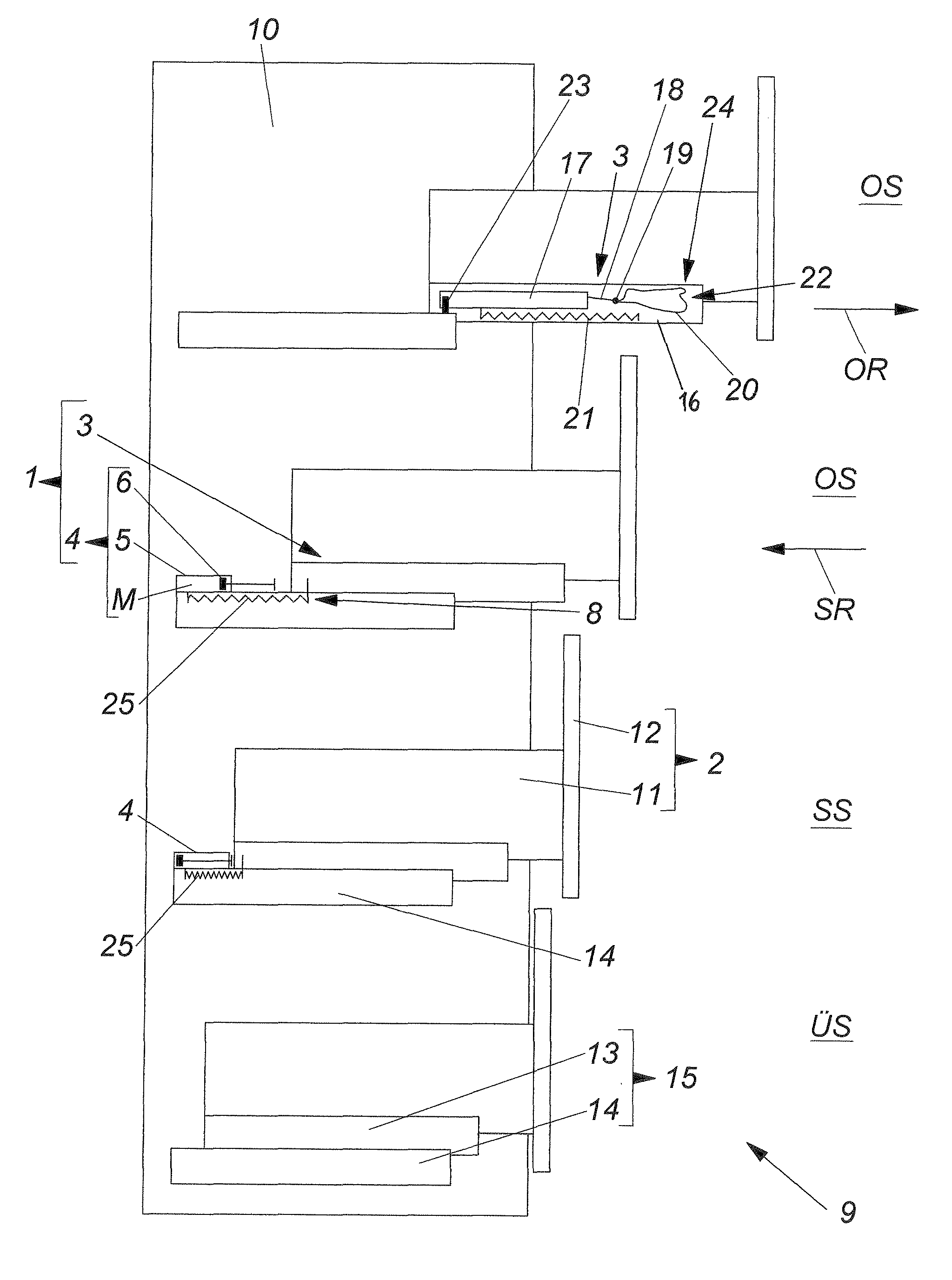
[0021] FIG. 1 diagrammatically shows moveable furniture parts in various positions,
[0022] FIG. 2 shows a damping device in the pre-damping region,
[0023] FIG. 3 shows a damping device in the main damping region,
[0024] FIG. 4 shows a damping device in the over-pressing region,
[0025] FIGS. 5 through 7 show 3D sectional views of the damping device in various positions,
[0026] FIG. 8 shows a damping device with two damping units arranged in parallel,
[0027] FIG. 9 shows a schematic graph of the damping force, and
[0028] FIG. 10 shows a graph for the damping force on the basis of specific values.
[0029] FIG. 1 generally shows an article of furniture 9 comprising a furniture carcass 10 and four moveable furniture parts 2 which are respectively disposed in different positions. In a downward direction the moveable furniture parts 2 (drawers) are in an open position OS, after moving in the closing direction SR in a further open position OS, after further moving in the closing direction SR in the closed position SS and after over-pressing in an over-pressing position UR behind the closed position SS. Each moveable furniture part 2 includes a drawer container 11 and a front panel 12. Each moveable furniture part 2 is mounted moveably to the furniture carcass 10 by way of an extension guide means 15. The extension guide means 15 includes a drawer rail 13 and a carcass rail 14 and optionally a central rail (not shown).
[0030] The essential components of the drive device 1 are the lockable ejection device 3 and the damping device 4. As shown in FIG. 1 the ejection device 3 is connected by way of a base plate 16 to the drawer rail 13 and to the moveable furniture part 2 respectively. The ejection slider 17 is mounted moveably on the base plate 16. The ejection force storage means 21 (as shown in FIG. 1, a compression spring which is not stressed) is fixed on the one hand to the base plate 16 and on the other hand to the ejection slider 17. A locking lever 18 is mounted pivotably to the ejection slider 17, wherein a locking pin 19 is arranged at the tip of the locking lever 18. That locking pin 19 is guided in a cardioid-shaped guide path 20 in the base plate 16. The entire ejection slider 17 is lockable to the base plate 16 by way of the locking device 24, wherein the locking device 24 is formed by the locking pin 19, the cardioid-shaped guide path 20 and its latching recess 22. The ejection slider 23 is connected or can be coupled at least portion-wise to the furniture carcass 10 by way of the entrainment portion 23 which is fixed with respect to the carcass.
[0031] As shown in FIG. 1 the damping device 4 for damping the closing movement of the moveable furniture part 2 is arranged on the carcass rail 14 and has the damping cylinder 5, the damping medium M and the damping piston 6 supported moveably in the damping cylinder 5. In addition provided in the region of the extension guide means 15 is the retraction device 8 which has the retraction force storage means 25 in the form of a tension spring. The damping device 4 is of such a configuration that a travel-dependent damping action is provided before reaching the closed position SS over the pre-damping region V and the main damping region H.
[0032] In detail in that respect attention is to be directed to FIG. 2 showing that the damping piston 6 together with the piston rod 29 is mounted moveably in the damping cylinder 5. It can be seen from this sectional view that a sealing ring 27 is arranged around the damping piston 6. In addition a damping groove 28 is provided at the inner surface of the damping cylinder so that the damping medium M can flow from the side of the damping piston 6, that is remote from the piston rod, to the side of the damping piston 6, that is towards the piston rod, and vice-versa. The damping cylinder 5 is closed by the cylinder cover 26 so that the damping medium M cannot issue. In this FIG. 2 the damping piston 6 is in the pre-damping region V.
[0033] In comparison in FIG. 3 the damping piston 6 is exactly in the region of the constriction 7 which is provided at the inside of the damping cylinder 5 and which forms the main damping region H. When the damping piston 6 is at that position the damping action or damping force D is at its greatest.
[0034] After that main damping region H has been passed over the position shown in FIG. 4 is reached, by the drive device 1 or the moveable furniture part 2 being disposed in the over-pressing region U between the closed position and the over-pressing position US. There is scarcely any damping force D on the part of the damping device 4 in that over-pressing region U.
[0035] FIGS. 5 through 7 show 3D sectional views of the damping device 1 corresponding to the positions in FIGS. 2 through 4.
[0036] Referring to FIGS. 2 through 7 they show a single piston-cylinder unit (damping unit) including the pre-damping region V, the main damping region H and the over-pressing region U. Alternatively or additionally the damping device 4 however can also comprise two damping units 4a and 4b, wherein as shown in FIG. 8 only the damping unit 4b has the constriction 7 so that this part of the damping unit 4b forms the main damping region H. Such a configuration is appropriate in particular when the damping unit 4b is to be retro-fitted in an already existing drive device 1. What is important is that the sum of the damping forces D of the individual damping units 4a and 4b again produces the desired damping force D for the moveable furniture part 2.
[0037] FIG. 9 schematically shows a graph with the development of the damping force D (given in N) along the closing travel (given in mm) of the moveable furniture part 2. As soon as the moveable furniture part 2 or the drive device 1 encounters the damping device 4 during the movement along the closing travel the damping force D rises, with the damping device 4 being in a pre-damping region V. Before the closed position SS is reached the damping force D of the damping device 4 rises greatly and reaches the main damping region H in which, in the event of incorrect operation, the attainment of the closed position is simulated. At the latest when the "true" closed position SS is reached the damping force D falls to a low range again. In the over-pressing region U between the closed position SS and the over-pressing position US the damping force D is again in a range which can be overcome upon desired triggering by applying a low triggering pressure.
[0038] FIG. 10 shows a graph with specific measurement values. The illustrated damping force D was measured at a closing speed of 100 mm/s with a load in the moveable furniture part 2 of 40 kg and with a length for the damping cylinder 5 of 35 mm. As can be seen, with the beginning of the pre-damping region V the damping force D rises relatively steeply to a value of about 35 N. In that region the damping force D in itself is speed-dependent. By virtue of the design configuration of the damping device 4 the arrangement provides for automatic leveling of the closing speed of the moveable furniture part 2. As soon as the main damping region H is reached the damping force D rises greatly and at about 125 N reaches the maximum value at which the overload protection mechanism is activated, whereupon the damping force D abruptly drops to about 70 N. That process with the overload peaks is repeated a plurality of times until the main damping region H has been passed over and the damping force D drops practically to 0 N.
[0039] Thus the present invention describes a drive device 1 in which travel-dependent damping provides that, in a region before the closed position SS is reached, the damping force D of the damping device 4 is increased so greatly that the attainment of the closed position is simulated for an operator in the event of incorrect operation, thereby providing an alternative kind of over-pressing protection.
* * * * *
D00000
D00001
D00002
D00003
D00004
D00005
XML
uspto.report is an independent third-party trademark research tool that is not affiliated, endorsed, or sponsored by the United States Patent and Trademark Office (USPTO) or any other governmental organization. The information provided by uspto.report is based on publicly available data at the time of writing and is intended for informational purposes only.
While we strive to provide accurate and up-to-date information, we do not guarantee the accuracy, completeness, reliability, or suitability of the information displayed on this site. The use of this site is at your own risk. Any reliance you place on such information is therefore strictly at your own risk.
All official trademark data, including owner information, should be verified by visiting the official USPTO website at www.uspto.gov. This site is not intended to replace professional legal advice and should not be used as a substitute for consulting with a legal professional who is knowledgeable about trademark law.