High-ceiling Tent Frame
Choi; Kwan Jun
U.S. patent application number 14/753989 was filed with the patent office on 2015-12-31 for high-ceiling tent frame. This patent application is currently assigned to Campvalley (Xiamen) Co., Ltd.. The applicant listed for this patent is Campvalley (Xiamen) Co., Ltd.. Invention is credited to Kwan Jun Choi.
| Application Number | 20150376913 14/753989 |
| Document ID | / |
| Family ID | 54929936 |
| Filed Date | 2015-12-31 |


View All Diagrams
| United States Patent Application | 20150376913 |
| Kind Code | A1 |
| Choi; Kwan Jun | December 31, 2015 |
HIGH-CEILING TENT FRAME
Abstract
A high-ceiling tent frame includes one or more frame units. Each frame unit includes three or more vertical poles and a center pole connected by supporting pole groups. Each frame unit also includes vertical pole fixed and slidable connecting bases installed at the vertical poles, and center fixed and slidable connecting bases installed at the center pole. Each supporting top pole group includes one or more pairs of first connecting pole units. The first connecting pole units in each pair are pivotally connected to each other. Each first connecting pole unit includes two first connecting poles pivotally connected to each other and forms an X-shape when the tent frame is unfolded. Adjacent frame units are connected to each other by sharing at least two vertical poles.
| Inventors: | Choi; Kwan Jun; (Xiamen, CN) | ||||||||||
| Applicant: |
|
||||||||||
|---|---|---|---|---|---|---|---|---|---|---|---|
| Assignee: | Campvalley (Xiamen) Co.,
Ltd. Xiamen CN |
||||||||||
| Family ID: | 54929936 | ||||||||||
| Appl. No.: | 14/753989 | ||||||||||
| Filed: | June 29, 2015 |
| Current U.S. Class: | 135/147 |
| Current CPC Class: | E04H 15/50 20130101 |
| International Class: | E04H 15/48 20060101 E04H015/48; E04H 15/60 20060101 E04H015/60 |
Foreign Application Data
| Date | Code | Application Number |
|---|---|---|
| Jun 27, 2014 | CN | 201420349197.5 |
| Sep 28, 2014 | CN | 201410506395.2 |
| Sep 28, 2014 | CN | 201420562771.5 |
| Nov 5, 2014 | CN | 201410615273.7 |
Claims
1. A high-ceiling tent frame, comprising: one or more frame units, each frame unit comprising: three or more vertical poles; a center pole; a plurality of supporting pole groups for connecting the center pole with the vertical poles; vertical pole fixed connecting bases installed at top ends of the vertical poles; vertical pole slidable connecting bases installed on pole bodies of the vertical poles and slidable along the pole bodies of the vertical poles; a center fixed connecting base installed at a bottom end of the center pole; and a center slidable connecting base installed on a pole body of the center pole and slidable along the pole body of the center pole, wherein: each supporting top pole group comprises one or more pairs of first connecting pole units; the first connecting pole units in each pair are pivotally connected to each other; each first connecting pole unit comprises two first connecting poles pivotally connected to each other and forms an X-shape when the tent frame is unfolded; and in each pair of the first connecting pole units, first one of the first connecting poles is pivotally connected to the center slidable connecting base, second one of the first connecting poles is pivotally connected to the center fixed connecting base, third one of the first connecting poles is pivotally connected to the vertical pole slidable connecting base of a corresponding vertical pole, and fourth one of the first connecting poles is pivotally connected to the vertical pole fixed connecting base of the corresponding vertical pole.
2. The high-ceiling tent frame according to claim 1, further comprising: side top pole groups each configured to connect two adjacent vertical poles; and oblique supporting poles each configured to connect a side top pole group to a corresponding vertical pole.
3. The high-ceiling tent frame according to claim 2, wherein: each side top pole group comprises two side top poles pivotally connected to each other and forms a substantially straight line when the tent frame is unfolded; one end of each side top pole is pivotally connected to the vertical pole fixed connecting base of a corresponding vertical pole in the two adjacent vertical poles; one end of each oblique supporting pole is pivotally connected to the vertical pole slidable connecting base of the corresponding vertical pole; and the other end of each oblique supporting pole is pivotally connected to the side top pole that is connected to the same corresponding vertical pole.
4. The high-ceiling tent frame according to claim 1, wherein within a respective frame unit: the three or more vertical poles comprises four vertical poles that form two vertical pole groups, wherein each vertical pole group comprises two adjacent vertical poles; the two adjacent vertical poles in each vertical pole group are connected by a side top pole group; the side top pole group comprises one or more pairs of second connecting pole units; the second connecting pole units in each pair are pivotally connected to each other; each second connecting pole unit comprises two second connecting poles pivotally connected to each other and forms an X-shape when the tent frame is unfolded; one of the second connecting poles of each second connecting pole unit is pivotally connected to the vertical pole slidable connecting base of a corresponding vertical pole; and the other one of the second connecting poles of each second connecting pole unit is pivotally connected to the vertical pole fixed connecting base of the corresponding vertical pole.
5. The high-ceiling tent frame according to claim 4, further comprising: an inner horizontal pole group for connecting two of the supporting top pole groups that are connected to different vertical pole groups within the respective frame unit, wherein the inner horizontal pole group comprises one of the following: two short poles, one ends thereof are pivotally connected to each other, and the other ends thereof are pivotally connected to the first connecting pole units of the supporting top pole groups at hinging points adjacent to the center pole; two short poles, one ends thereof are pivotally connected to each other, and the other ends are pivotally connected to the first connecting pole units of the corresponding supporting top pole group at upper hinging points of the first connecting pole units; two short poles, one ends thereof are pivotally connected to each other, and the other ends are pivotally connected to the first connecting pole units of the corresponding supporting top pole group at the upper hinging points of the first connecting pole units, wherein each short pole is supported by an oblique supporting pole, wherein one end of the oblique supporting pole is pivotally connected to a pole body of the corresponding short pole and the other end is pivotally connected to a lower hinging point of a corresponding first connecting pole unit; or one or more pairs of third connecting pole units, wherein the third connecting pole units in each pair are pivotally connected to each other, each third connecting pole unit comprises two third connecting poles pivotally connected to each other and forms an X-shape when the tent frame is unfolded, one of the third connecting poles of each third connecting pole unit is pivotally connected to the first connecting pole units of the corresponding supporting top pole group at the upper hinging points of the first connecting pole units and the other one of the third connecting poles of each third connecting pole unit is pivotally connected to the first connecting pole units of the corresponding supporting top pole group at the lower hinging points of the first connecting pole units.
6. The high-ceiling tent frame according to claim 4, further comprising: an inner horizontal pole group for connecting two adjacent vertical poles in the two vertical pole groups within the respective frame unit, wherein the inner horizontal pole group comprises two short poles, one ends thereof are pivotally connected to each other, and the other ends are pivotally connected to the vertical pole fixed connecting bases of the corresponding vertical poles; and each short pole is supported by an oblique supporting pole, wherein one end of the oblique supporting pole is pivotally connected to a pole body of the corresponding short pole and the other end is pivotally connected to the vertical pole slidable connecting base of a corresponding vertical pole.
7. The high-ceiling tent frame according to claim 1, further comprising: a connecting pin and a spring disposed between the center pole and the center fixed connecting base, wherein a first elongated slot or a first pin hole is formed at a bottom end portion of the center pole; the center fixed connecting base includes: (i) a connecting pole hinging part for receiving the first connecting poles, (ii) a blind hole for receiving the center pole, (iii) a second pin hole corresponding to the first elongated slot of the center pole and formed adjacent to a mouth part of the blind hole, or a second elongated slot corresponding to the first pin hole of the center pole and formed on a side wall of the blind hole; the connecting pin penetrates through the corresponding elongated slot and the corresponding pin hole, connecting the center pole with the center fixed connecting base; and the spring is placed in the blind hole, one end of the spring presses against a bottom end of the center pole and the other end presses against a bottom part of the blind hole.
8. The high-ceiling tent frame according to claim 1, further comprising: supporting pieces installed on the first connecting poles that are connected to the vertical pole fixed connecting bases, wherein each supporting piece comprises: a connecting part fixedly connected to a corresponding first connecting pole; and a horizontal pole for supporting a tent fabric, wherein the horizontal pole and the connecting part are fixedly connected to each other at a predetermined angle.
9. The high-ceiling tent frame according to claim 1, further comprising: one or more water accumulation preventing pole groups, wherein a water accumulation preventing pole group is connected to a corresponding first connecting pole unit and comprises: a slidable connecting piece pivotally connected to one connecting pole of the corresponding first connecting pole unit; and a fabric supporting pole, a pole body thereof is slidably connected to the slidable connecting piece and one end thereof is pivotally connected to the other connecting pole of the corresponding first connecting pole unit, such that the fabric supporting pole is disposed substantially vertically and upwardly when the tent frame is unfolded.
10. The high-ceiling tent frame according to claim 9, wherein the slidable connecting piece is pivotally connected to the one connecting pole of the corresponding first connecting pole unit by a bracket, wherein the bracket is pivotally connected to the slidable connecting piece and fixedly connected to the one connecting pole of the corresponding first connecting pole unit.
11. The high-ceiling tent frame according to claim 1, further comprising: one or more water accumulation preventing pole groups, wherein a water accumulation preventing pole group comprising: an eave supporting pole; an eave moving pole, one end thereof is pivotally connected to one end of the eave supporting pole, and the other end or a pole body of the eave moving pole is pivotally connected to the third or fourth one of the first connecting poles; and a connecting part, one end thereof is pivotally connected to the pole body of the eave pole and the other end thereof is pivotally connected to the fourth one of the first connecting poles.
12. The high-ceiling tent frame according to claim 11, wherein the eave moving pole comprises: a first pole; a second pole, one end thereof is rotatably connected to one end of the first pole; and a stop block disposed at the connected ends of the first pole and the second pole and configured to limit a rotating angle of the first and second poles.
13. The high-ceiling tent frame according to claim 11, wherein the vertical poles, the eave pole or both the vertical poles and the eave pole are retractable poles.
14. The high-ceiling tent frame according to claim 1, wherein the one or more frame units comprise at least two frame units, wherein two adjacent frame units are connected to each other by sharing at least two vertical poles.
Description
CROSS-REFERENCE TO RELATED APPLICATION
[0001] The present application claims priority of Chinese Utility Model Application Numbers CN 201420349197.5 filed Jun. 27, 2014 and CN 201420562771.5 filed Sep. 28, 2014, and Chinese Patent Application Numbers CN 201410506395.2 filed Sep. 28, 2014 and CN 201410615273.7 filed Nov. 5, 2014, the entire contents of which applications are incorporated herein for all purposes by this reference.
FIELD OF INVENTION
[0002] The present invention relates to an outdoor product, in particular, to a high-ceiling tent frame.
DESCRIPTION OF RELATED ART
[0003] As an outdoor leisure product, tents are widely used in various occasions. A common tent frame is formed by connecting a plurality of groups of vertical poles to top poles, wherein the top poles form a top support. The tents applying such frames have common drawbacks in that the structures thereof are generally more complex, a plurality of groups of poles are needed to support tent fabrics, the frames are difficult and time-consuming to establish and the manufacturing costs are increased.
[0004] Chinese invention patent ZL201310429420.7 discloses a foldable tent eave frame structure, which comprises a tent frame and an eave pole. The tent frame comprises vertical posts, tent poles and oblique supporting poles. Fixed bases are fixedly arranged at top ends of the vertical posts. Slidable bases, which can slide up and down along the vertical posts, are slidably connected onto the vertical posts. First ends of the tent poles are pivoted onto the fixed bases. First ends of the oblique supporting poles are pivoted onto the slidable bases and second ends of the oblique supporting poles are pivoted onto the tent poles. The slidable bases slide up and down along the vertical posts to fold or unfold the tent frame. The tent frame is provided with a sliding way. A first end of the eave pole is pivoted onto the oblique supporting poles. The eave pole can move relative to the sliding way to enable a second end of the eave pole to get far away from or close to the sliding way to realize the unfolding or folding of the eave pole. The unfolding or folding of the tent frame induces the unfolding or folding of the eave pole.
[0005] However, poles, which mainly play a role of folding, of the conventional tents are centralized between two vertical posts. Thus, the height of an entrance/exit of the tent is inherently reduced, causing inconvenience to users. In addition, since scissors-shaped connecting pole groups of the tent are arranged on the periphery of the tent and there are no similar poles inside, items cannot be hung inside.
[0006] Although one eave pole is added to the tent and applied to support the tent fabric, a probability that water is accumulated between the vertical poles and the center base on rainy days still exists. The problem of water accumulation on rainy days cannot be fully solved.
[0007] Given the above background, there is a need in the art for a tent frame that provides adequate space with a stable structure, capability of hanging items inside, and/or capability of preventing water from accumulating on rainy days.
[0008] The information disclosed in this Background section is only for enhancement of understanding of the general background of the invention and should not be taken as an acknowledgement or any form of suggestion that this information forms the prior art already known to a person skilled in the art.
SUMMARY OF INVENTION
[0009] In various aspects, the present invention provides a high-ceiling tent frame with a stable structure, capability of hanging items inside and/or capability of preventing water from accumulating on rainy days.
[0010] In some aspects, a high-ceiling tent frame of the present invention comprises one or more frame units. Each frame unit comprises: three or more vertical poles; a center pole; a plurality of supporting pole groups for connecting the center pole with the vertical poles; vertical pole fixed connecting bases installed at top ends of the vertical poles; vertical pole slidable connecting bases installed on pole bodies of the vertical poles and slidable along the pole bodies of the vertical poles; a center fixed connecting base installed at a bottom end of the center pole; and a center slidable connecting base installed on a pole body of the center pole and slidable along the pole body of the center pole, wherein: each supporting top pole group comprises one or more pairs of first connecting pole units; the first connecting pole units in each pair are pivotally connected to each other; each first connecting pole unit comprises two first connecting poles pivotally connected to each other and forms an X-shape when the tent frame is unfolded; and in each pair of the first connecting pole units, first one of the first connecting poles is pivotally connected to the center slidable connecting base, second one of the first connecting poles is pivotally connected to the center fixed connecting base, third one of the first connecting poles is pivotally connected to the vertical pole slidable connecting base of a corresponding vertical pole, and fourth one of the first connecting poles is pivotally connected to the vertical pole fixed connecting base of the corresponding vertical pole.
[0011] In one aspect, the high-ceiling tent frame further comprises: side top pole groups each configured to connect two adjacent vertical poles; and oblique supporting poles each configured to connect a side top pole group to a corresponding vertical pole. Each side top pole group comprises two side top poles pivotally connected to each other and forms a substantially straight line when the tent frame is unfolded; one end of each side top pole is pivotally connected to the vertical pole fixed connecting base of a corresponding vertical pole in the two adjacent vertical poles; one end of each oblique supporting pole is pivotally connected to the vertical pole slidable connecting base of the corresponding vertical pole; and the other end of each oblique supporting pole is pivotally connected to the side top pole that is connected to the same corresponding vertical pole.
[0012] In some aspects, within a respective frame unit: the three or more vertical poles comprises four vertical poles that form two vertical pole groups, wherein each vertical pole group comprises two adjacent vertical poles; the two adjacent vertical poles in each vertical pole group are connected by a side top pole group; the side top pole group comprises one or more pairs of second connecting pole units; the second connecting pole units in each pair are pivotally connected to each other; each second connecting pole unit comprises two second connecting poles pivotally connected to each other and forms an X-shape when the tent frame is unfolded; one of the second connecting poles of each second connecting pole unit is pivotally connected to the vertical pole slidable connecting base of a corresponding vertical pole; and the other one of the second connecting poles of each second connecting pole unit is pivotally connected to the vertical pole fixed connecting base of the corresponding vertical pole.
[0013] In one aspect, the high-ceiling tent frame further comprises an inner horizontal pole group for connecting two of the supporting top pole groups that are connected to different vertical pole groups within the respective frame unit. The inner horizontal pole group comprises one of the following: (i) two short poles, one ends thereof are pivotally connected to each other, and the other ends thereof are pivotally connected to the first connecting pole units of the supporting top pole groups at hinging points adjacent to the center pole; (ii) two short poles, one ends thereof are pivotally connected to each other, and the other ends are pivotally connected to the first connecting pole units of the corresponding supporting top pole group at upper hinging points of the first connecting pole units; (iii) two short poles, one ends thereof are pivotally connected to each other, and the other ends are pivotally connected to the first connecting pole units of the corresponding supporting top pole group at the upper hinging points of the first connecting pole units, wherein each short pole is supported by an oblique supporting pole, wherein one end of the oblique supporting pole is pivotally connected to a pole body of the corresponding short pole and the other end is pivotally connected to a lower hinging point of a corresponding first connecting pole unit; or (iv) one or more pairs of third connecting pole units, wherein the third connecting pole units in each pair are pivotally connected to each other, each third connecting pole unit comprises two third connecting poles pivotally connected to each other and forms an X-shape when the tent frame is unfolded, one of the third connecting poles of each third connecting pole unit is pivotally connected to the first connecting pole units of the corresponding supporting top pole group at the upper hinging points of the first connecting pole units and the other one of the third connecting poles of each third connecting pole unit is pivotally connected to the first connecting pole units of the corresponding supporting top pole group at the lower hinging points of the first connecting pole units.
[0014] In another aspect, the high-ceiling tent frame further comprises an inner horizontal pole group for connecting two adjacent vertical poles in the two vertical pole groups within the respective frame unit. The inner horizontal pole group comprises two short poles, one ends thereof are pivotally connected to each other, and the other ends are pivotally connected to the vertical pole fixed connecting bases of the corresponding vertical poles; and each short pole is supported by an oblique supporting pole, wherein one end of the oblique supporting pole is pivotally connected to a pole body of the corresponding short pole and the other end is pivotally connected to the vertical pole slidable connecting base of a corresponding vertical pole.
[0015] In an aspect, the high-ceiling tent frame further comprises a connecting pin and a spring disposed between the center pole and the center fixed connecting base. A first elongated slot or a first pin hole is formed at a bottom end portion of the center pole; the center fixed connecting base includes: (i) a connecting pole hinging part for receiving the first connecting poles, (ii) a blind hole for receiving the center pole, (iii) a second pin hole corresponding to the first elongated slot of the center pole and formed adjacent to a mouth part of the blind hole, or a second elongated slot corresponding to the first pin hole of the center pole and formed on a side wall of the blind hole; the connecting pin penetrates through the corresponding elongated slot and the corresponding pin hole, connecting the center pole with the center fixed connecting base; and the spring is placed in the blind hole, one end of the spring presses against a bottom end of the center pole and the other end presses against a bottom part of the blind hole.
[0016] In some aspects, the high-ceiling tent frame further comprises supporting pieces installed on the first connecting poles that are connected to the vertical pole fixed connecting bases. Each supporting piece comprises: a connecting part fixedly connected to a corresponding first connecting pole; and a horizontal pole for supporting a tent fabric, wherein the horizontal pole and the connecting part are fixedly connected to each other at a predetermined angle.
[0017] In some aspects, the high-ceiling tent frame further comprises one or more water accumulation preventing pole groups. A water accumulation preventing pole group is connected to a corresponding first connecting pole unit and comprises: a slidable connecting piece pivotally connected to one connecting pole of the corresponding first connecting pole unit; and a fabric supporting pole, a pole body thereof is slidably connected to the slidable connecting piece and one end thereof is pivotally connected to the other connecting pole of the corresponding first connecting pole unit, such that the fabric supporting pole is disposed substantially vertically and upwardly when the tent frame is unfolded.
[0018] In an aspect, the slidable connecting piece is pivotally connected to the one connecting pole of the corresponding first connecting pole unit by a bracket, wherein the bracket is pivotally connected to the slidable connecting piece and fixedly connected to the one connecting pole of the corresponding first connecting pole unit.
[0019] In some aspects, the high-ceiling tent frame further comprises one or more water accumulation preventing pole groups. A water accumulation preventing pole group comprising: an eave supporting pole; an eave moving pole, one end thereof is pivotally connected to one end of the eave supporting pole, and the other end or a pole body of the eave moving pole is pivotally connected to the third or fourth one of the first connecting poles; and a connecting part, one end thereof is pivotally connected to the pole body of the eave pole and the other end thereof is pivotally connected to the fourth one of the first connecting poles.
[0020] In an aspect, the eave moving pole comprises: a first pole; a second pole, one end thereof is rotatably connected to one end of the first pole; and a stop block disposed at the connected ends of the first pole and the second pole and configured to limit a rotating angle of the first and second poles.
[0021] In some aspects, the vertical poles, the eave pole or both the vertical poles and the eave pole are retractable poles.
[0022] In some aspects, the high-ceiling tent frame comprise at least two frame units, wherein two adjacent frame units are connected to each other by sharing at least two vertical poles.
[0023] The present invention has at least the following beneficial effects.
[0024] By arranging the supporting top pole groups between the vertical poles and the center pole, pressure applied to the center pole can be dispersed to vertical poles and thus the structure is stable. Since each supporting top pole group is formed by a plurality of first connecting pole units, each of which includes two first connecting poles, the first connecting poles can support with each other and thus the tent frame is more stable. Since the first connecting poles form the X-shape when unfolded and a quadrilateral structure is formed between two groups of first connecting pole units, the first connecting pole units can be used for hanging items.
[0025] Since the elongated slot is formed in the center pole or the side wall of the blind hole, the spring is arranged between the center pole and the center fixed connecting base. The spring is in a compressed state when the tent frame is unfolded and applies an upward force to the center pole. The center pole is pushed upward, tightening the tent fabric and thus reducing formation of pits and preventing water accumulation.
[0026] By arranging the water accumulation preventing pole group(s), the tent fabric can be further tightened. The tent poles can also support the tent fabric, and thus reduce formation of pits and prevent water accumulation.
[0027] The methods and apparatuses of the present invention have other features and advantages which will be apparent from or are set forth in more detail in the accompanying drawings, which are incorporated herein, and the following Detailed Description, which together serve to explain certain principles of the present invention.
BRIEF DESCRIPTION OF THE DRAWINGS
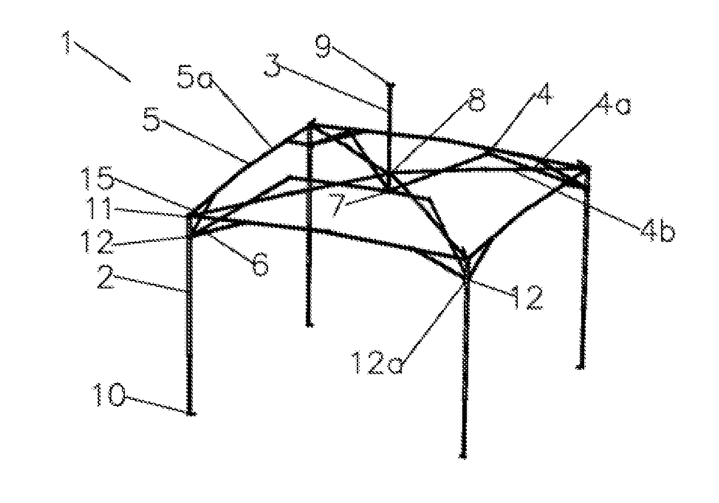
[0028] FIG. 1 is a schematic diagram illustrating a first exemplary high-ceiling tent frame according to some embodiments of the present invention.
[0029] FIG. 2 is a partially enlarged view of FIG. 1, illustrating connection structures at or adjacent to a bottom part of a center pole of the high-ceiling tent frame.
[0030] FIG. 3 is a partially enlarged view of FIG. 1, illustrating connection structures of top parts of vertical poles of the high-ceiling tent frame.
[0031] FIG. 4 is a schematic diagram illustrating the high-ceiling tent frame of FIG. 1 in a folding process.
[0032] FIG. 5 is a schematic diagram illustrating the high-ceiling tent frame of FIG. 1 in a folded state.
[0033] FIG. 6 is a schematic diagram illustrating a second exemplary high-ceiling tent frame according to some embodiments of the present invention.
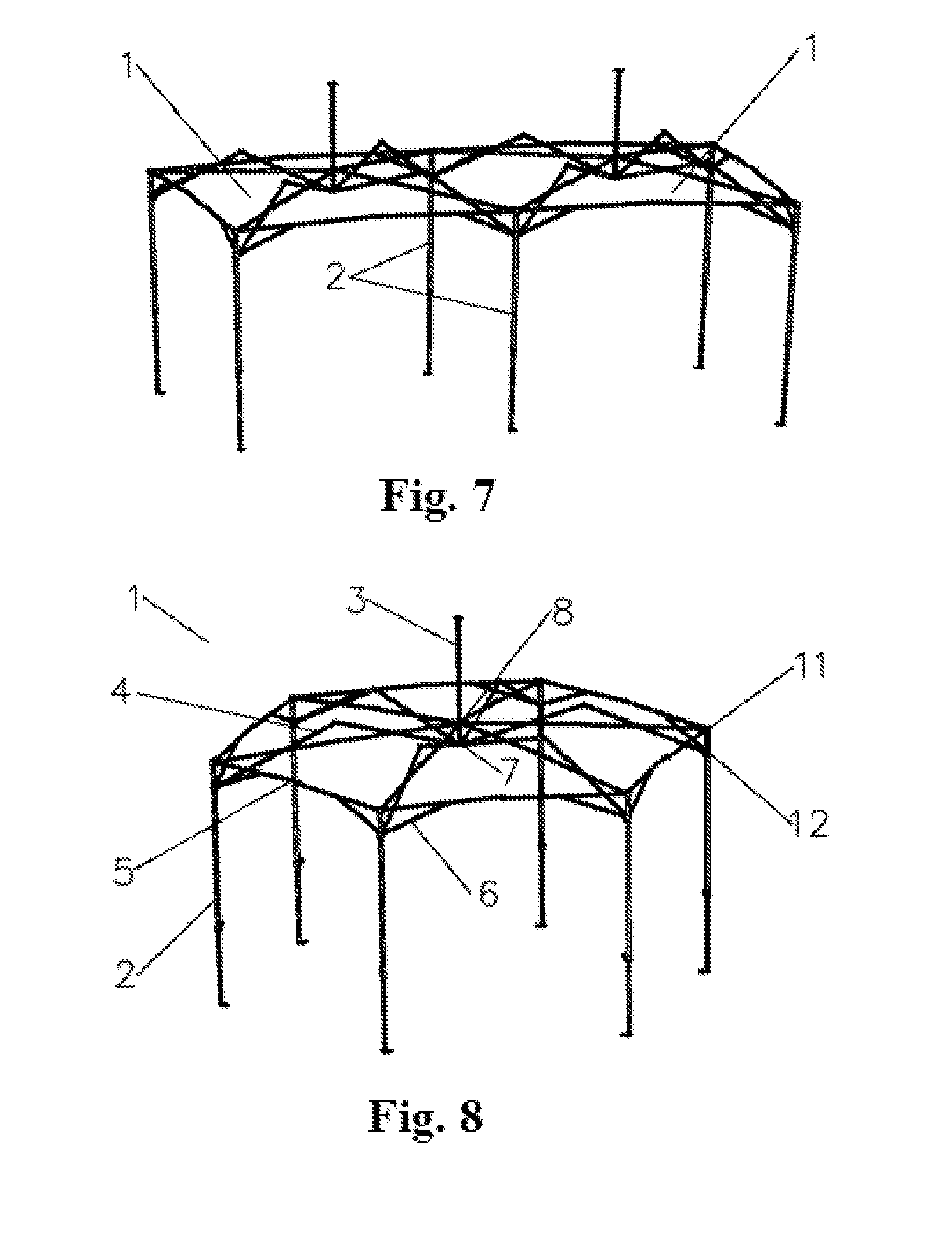
[0034] FIG. 7 is a schematic diagram illustrating a third exemplary high-ceiling tent frame according to some embodiments of the present invention.
[0035] FIG. 8 is a schematic diagram illustrating a fourth exemplary high-ceiling tent frame according to some embodiments of the present invention.
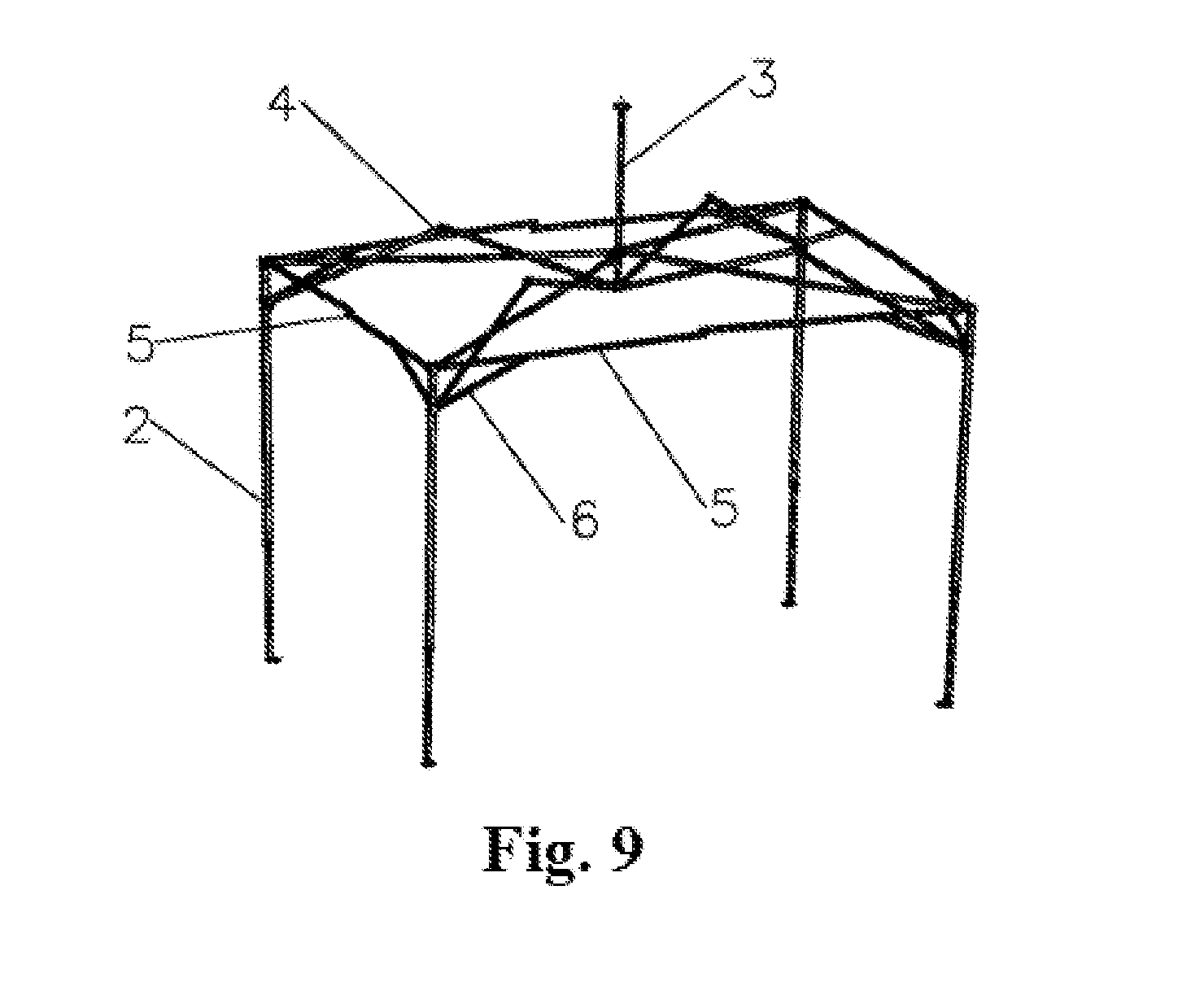
[0036] FIG. 9 is a schematic diagram illustrating a fifth exemplary high-ceiling tent frame according to some embodiments of the present invention.
[0037] FIG. 10 is a schematic diagram illustrating a sixth exemplary high-ceiling tent frame according to some embodiments of the present invention.
[0038] FIG. 11 is a partially enlarged view of FIG. 10, illustrating connection structures at or adjacent to a bottom part of a center pole of the high-ceiling tent frame.
[0039] FIG. 12 is a partial exploded view of FIG. 11.
[0040] FIG. 13 is a sectional and partially enlarged view of FIG. 10, illustrating connection structures at or adjacent to a bottom part of a center pole of the high-ceiling tent frame.
[0041] FIG. 14 is a partial enlarged view of A in FIG. 10.
[0042] FIG. 15 is a schematic diagram illustrating a seventh exemplary high-ceiling tent frame according to some embodiments of the present invention.
[0043] FIG. 16 is a partial enlarged view of B in FIG. 15.
[0044] FIG. 17 is a partial enlarged view of C in FIG. 16.
[0045] FIG. 18 is a partially enlarged view of FIG. 15, illustrating a folded eave supporting pole.
[0046] FIG. 19 is a partially enlarged view of FIG. 15, illustrating connection structures at or adjacent to a bottom part of a center pole of the high-ceiling tent frame.
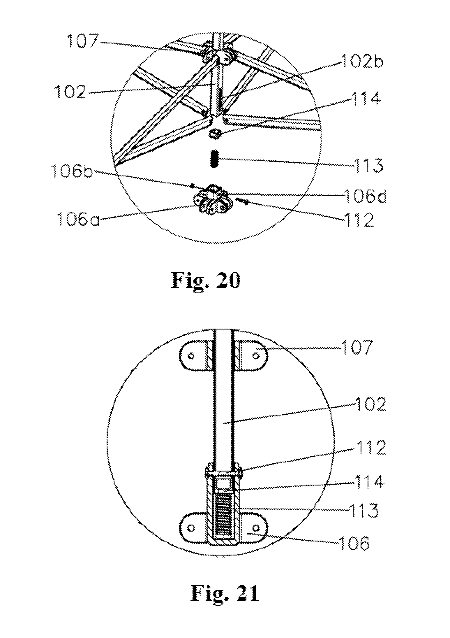
[0047] FIG. 20 is a partial exploded view of FIG. 19.
[0048] FIG. 21 is a sectional and partially enlarged view of FIG. 19, illustrating connection structures at or adjacent to a bottom part of a center pole of the high-ceiling tent frame.
[0049] FIG. 22 is a schematic diagram illustrating an exemplary water accumulation preventing pole group according to some embodiments of the present invention.
[0050] FIG. 23 is a schematic diagram illustrating an exemplary connection between a slidable connecting piece and a first connecting pole according to some embodiments of the present invention.
[0051] FIG. 24 is a schematic diagram illustrating a folding process of the second exemplary water accumulation preventing pole group in FIG. 23.
[0052] FIG. 25 is a schematic diagram illustrating the second exemplary water accumulation preventing pole group in FIG. 23 in a folded state.
[0053] FIG. 26 is a schematic diagram illustrating an eighth exemplary high-ceiling tent frame according to some embodiments of the present invention.
[0054] FIG. 27 is a schematic diagram illustrating a ninth exemplary high-ceiling tent frame according to some embodiments of the present invention.
[0055] FIG. 28 is a schematic diagram illustrating a tenth exemplary high-ceiling tent frame according to some embodiments of the present invention.
[0056] FIG. 29 is a schematic diagram illustrating an eleventh exemplary high-ceiling tent frame according to some embodiments of the present invention.
[0057] FIG. 30 is a schematic diagram illustrating a twelfth exemplary high-ceiling tent frame according to some embodiments of the present invention.
[0058] FIG. 31 is a schematic diagram illustrating a thirteenth exemplary high-ceiling tent frame according to some embodiments of the present invention.
[0059] Partial hinging pins are omitted in the drawings and numeral references in the drawings correspond to the follows: [0060] 1--frame unit; [0061] 2, 101, 201--vertical pole; [0062] 3, 102, 202--center pole; [0063] 3a--slot structure; [0064] 4, 103, 203--supporting top pole group; [0065] 4a, 103a, 231--first connecting pole unit; [0066] 4b, 103b, 2311--first connecting pole; [0067] 5, 104, 204--side top pole group; [0068] 5a--side top pole; [0069] 6, 105, 252--oblique supporting pole; [0070] 7, 106--center fixed connecting base; [0071] 8, 107--center slidable connecting base; [0072] 9, 15, 108--supporting piece; [0073] 10, 109--bottom foot piece; [0074] 11, 110, 210--vertical pole fixed connecting base; [0075] 12, 111, 211--vertical pole slidable connecting base; [0076] 12a, 111a, 211a--stop device; [0077] 13--compression spring; [0078] 14--pin; [0079] 15a--connecting part; [0080] 15b--horizontal pole; [0081] 102a, 106d--pin hole; [0082] 102b--elongated slot; [0083] 104a--side top pole; [0084] 106a--first connecting pole hinging part; [0085] 106b--blind hole; [0086] 106c--elongated slot; [0087] 112--connecting pin; [0088] 113--spring; [0089] 114--inner plug; [0090] 115--eave supporting pole; [0091] 116, 118--eave moving pole; [0092] 117--connecting part or sheet; [0093] 118a--first straight pole; [0094] 118b--second straight pole; [0095] 118c--stop block; [0096] 119--fabric supporting pole; [0097] 120, 207--slidable connecting piece; [0098] 121--stepped metal sheet; [0099] 231a--upper hinging point; [0100] 231b--lower hinging point; [0101] 2312--center hinging point; [0102] 241--second connecting pole unit; [0103] 2411--second connecting pole; [0104] 205, 208--inner horizontal pole group; [0105] 251--short pole; [0106] 206--fixed connecting base; [0107] 281--third connecting pole unit; [0108] 2811--third connecting pole.
DETAILED DESCRIPTION
[0109] Reference will now be made in detail to various embodiments of the present invention(s), examples of which are illustrated in the accompanying drawings and described below. While the invention(s) will be described in conjunction with exemplary embodiments, it will be understood that present description is not intended to limit the invention(s) to those exemplary embodiments. On the contrary, the invention(s) is/are intended to cover not only the exemplary embodiments, but also various alternatives, modifications, equivalents and other embodiments, which may be included within the spirit and scope of the invention as defined by the appended claims.
[0110] A high-ceiling tent frame of the present invention in general comprises one or more frame units such as frame unit 1. The specific number of the frame units can be determined or adjusted according to the actually needed internal space of the tent or personal preference. In embodiments with two or more frame units, the adjacent frame units are connected to each other, for example by sharing vertical poles. By way of illustration and for describing structures of frame unit 1, FIG. 1 illustrates a first exemplary high-ceiling tent frame with one frame unit 1.
[0111] In some embodiments, the frame unit 1 comprises three or more vertical poles 2. The specific number of the vertical poles 2 can also be determined or adjusted according to the needed internal space of the tent or personal preference. As an example, FIG. 1 illustrates four vertical poles 2 arranged in a square shape. In some embodiments, the frame unit 1 also includes a center pole 3 and a supporting top pole group 4 used for connecting the center pole 3 with the vertical poles 2. When in use, top ends of the vertical poles 2 and the center pole 3 are in direct contact with and support the tent fabric. In some embodiments, the vertical poles 2 are retractable poles. In some embodiments, side top pole groups 5 are connected between every two adjacent vertical poles 2 and an oblique supporting pole 6 is additionally connected between each vertical pole 2 and each side top pole group 5 connected with this vertical pole 2. Side top pole groups 5 and the oblique supporting poles 6 strengthen the tent frame, making it firmer when the tent frame is unfolded. However, it should be understood that the side top pole groups 5 and the oblique supporting poles 6 are optional or additional components, not necessary for the tent frame of the present invention.
[0112] The center pole 3 is placed vertically or substantially vertically when the tent frame is unfolded. In some embodiments, a center fixed connecting base 7 is installed at a bottom end of the center pole 3. A center slidable connecting base 8 which can slide on the center pole 3 is installed on a pole body of the center pole 3. A supporting piece 9 used for supporting the tent fabric is installed at a top end of the center pole 3.
[0113] In some embodiments, the vertical poles 2 are placed vertically or substantially vertically when the tent frame is unfolded. In some embodiments, the vertical poles 2 is obliquely placed at a predetermined tilt angle relative to the ground. In some embodiments, bottom foot pieces 10 are installed at bottom ends of the vertical poles 2. Vertical pole fixed connecting bases 11 are installed at top ends of the vertical poles 2. Vertical pole slidable connecting bases 12 which can slide along the vertical poles 2 are installed on pole bodies of the vertical poles 2.
[0114] In some embodiments, the vertical pole slidable connecting bases 12 are provided with stop devices 12a for preventing the vertical pole slidable connecting bases 12 from falling downwards along the pole bodies of the vertical poles 2 when the tent frame is unfolded.
[0115] The center fixed connecting base 7, the center slidable connecting base 8, the supporting piece 9, the bottom foot pieces 10, the vertical pole fixed connecting bases 11, the vertical pole slidable connecting bases 12 and the stop devices 12a are the same or similar to those in the art and are thus not described herein in details.
[0116] In some embodiments, for example as shown in FIG. 2, the first exemplary high-ceiling tent frame further comprises a compression spring 13. In addition, in some embodiments, the center pole 3 is a hollow pole. A pin 14 is inserted into the pole body of the center pole 3 close to a position at which the center fixed connecting base 7 is installed. The compression spring 13 is installed in the center pole 3, where one end of the compression spring 13 presses against the center fixed connecting base 7, and the other end presses against the pin 14. The compression spring 13 is always in a compressed state after being installed in the center pole 3 and thus provides an upward elastic force to the center pole 3. As such, the tent fabric supported by the center pole 3 is always in a tightened state when the tent frame is unfolded to prevent water from being accumulated on rainy days.
[0117] In some embodiments, a slot structure 3a is formed at the center pole, at a position where the compression spring 13 is installed. The length of the slot structure 3a can be equal to or slightly smaller than the length of the compression spring 13. The slot structure 3a facilitates the observation of the working state of the compression spring 13, and the installation and replacement of the compression spring 13.
[0118] In some embodiments, each supporting top pole group 4 comprises one or more pairs of first connecting pole units 4a which are pivotally connected to each other. For example, each supporting top pole group 4 comprises two pairs of first connecting pole units 4a. Each first connecting pole unit 4a comprises two first connecting poles 4b which are pivotally connected to each other and form an X-shape when the tent frame is unfolded. In each supporting top pole group 4, as shown in FIG. 2, one first connecting pole 4b of the first connecting pole unit 4a connected with the center pole 3 is pivotally connected to the center pole 3 through the center slidable connecting base 8, and the other first connecting pole 4b is pivotally connected to the center pole 3 through the center fixed connecting base 7. As shown in FIG. 3, one first connecting pole 4b of the first connecting pole unit 4a connected with the vertical poles 2 is pivotally connected to the vertical poles 2 through the vertical pole slidable connecting bases 12. The other first connecting pole 4b is pivotally connected to the vertical poles 2 through the vertical pole fixed connecting bases 11. Pivotal connection disclosed herein can be achieved by pins, hinges, bolts, screws or the like.
[0119] In some embodiments, a supporting piece 15 is additionally or optionally installed on this first connecting pole 4b. The supporting piece 15 comprises a connecting part 15a fixedly connected with the first connecting pole 4b and a horizontal pole 15b used for supporting the tent fabric. In one embodiment, the connecting part 15a is fixed on the first connecting pole 4b through a pin. The horizontal pole 15b and the connecting part 15a are fixedly connected according to a predetermined angle, and the specific angle can be determined according to the actual needs or personal preference as long as the horizontal pole 15b can support the tent fabric when the tent or tent frame is unfolded. By way of illustration, FIG. 3 shows only one supporting piece 15 installed on the first connecting pole 4b. However, it should be understood that a plurality of supporting pieces 15 can be installed on the same first connecting pole 4b according to the actual needs or preference.
[0120] In some embodiments, each side top pole group 5 comprises two side top poles 5a which are pivotally connected to each other and form a substantially straight line when the tent frame is unfolded. For example, as shown in FIG. 1, certain ends, which are not pivotally connected to each other, of the side top poles 5a are pivotally connected to the vertical poles 2 through the vertical pole fixed connecting bases 11.
[0121] In some embodiments, one end of each oblique supporting pole 6 is connected with the vertical pole 2 through the vertical pole slidable connecting base 12, and the other end is pivotally connected to the side top pole 5a pivotally connected to the same one vertical pole 2. When the tent frame is unfolded, the vertical pole 2, one section of the side top pole 5a and the oblique supporting pole 6 form a triangle. In one embodiment, two side top poles 5a and two oblique supporting poles 6 are pivotally connected to each vertical pole 2.
[0122] As shown in FIG. 1, in some embodiments, to unfold the tent or the tent frame, the vertical poles 2 of the tent frame are placed vertically or substantially vertically and are pulled open to predetermined positions. The vertical pole slidable connecting bases 12 are slid or simultaneously slid upwards to predetermined positions. The vertical pole slidable connecting bases 12 are fixed on the vertical poles 2 by the stop devices 12a. The bottom foot pieces 10 are fixed on the ground and thus the unfolding of the tent frame is realized. The tent fabric is placed on the tent frame, prior to or subsequent to the unfolding of the tent frame. The tent fabric is supported by the supporting pieces 9, the supporting pieces 15 and the top parts of the vertical poles 2.
[0123] As shown in FIG. 4, in some embodiments, to fold the tent or the tent frame, the tent fabric is retrieved or put away. The bottom foot pieces 10 and the stop devices 12a are loosened. The vertical poles 2 are retracted or simultaneously refracted to a shorter or the shortest state. Then the vertical pole slidable connecting bases 12 are slid downwards. The two first connecting poles 4b on each connecting pole unit 4a are respectively clockwise and anticlockwise rotated. The four vertical poles 2 are driven to move towards the direction of the center pole 3. The center slidable connecting base 8 slides upwards along the center pole 3 under the drive of the first connecting pole units 4a. The center fixed connecting base 7 moves downwards together with the center pole 3 under the drive of the first connecting pole units 4a. At the end, all poles are folded together as shown in FIG. 5.
[0124] Referring to FIG. 6, there depicts a second exemplary high-ceiling tent frame according to some embodiments of the present invention. As shown in FIG. 6, in some embodiments, a tent frame of the present invention comprises two frame units 1 connected with each other. Each frame unit 1 is the same or substantially the same as the frame unit 1 in the first exemplary high-ceiling tent frame disclosed above.
[0125] In some embodiments, the two frame units 1 share two vertical poles 2 and a side top pole group 5. It should be understood that the number of the frame units 1 is readily adjustable. In some embodiments, the tent frame includes more than two frame units 1, in which two adjacent frame units are connected to each other by sharing two vertical poles 2 and one side top pole group 5. In some embodiments, the tent frame includes the supporting pieces 15. The supporting pieces 15 are optional, and in some embodiments, the tent frame does not include the supporting pieces 15.
[0126] The folding and folding process of the second exemplary high-ceiling tent frame is similar to that of the first exemplary high-ceiling tent frame, and thus is not described herein in details.
[0127] Referring to FIG. 7, there depicts a third exemplary high-ceiling tent frame according to some embodiments of the present invention. As shown in FIG. 7, the third exemplary high-ceiling tent frame comprises two frame units 1 connected with each other. The frame unit of the third exemplary high-ceiling tent frame is substantially the same as that of the first exemplary high-ceiling tent frame, except the arrangement of the side top pole groups 5 and the oblique top poles 6 is different. As shown in FIG. 7, two frame units 1 share two vertical poles 2.
[0128] In consideration of that the stress at a connecting position between the two frame units 1 is small, the third exemplary high-ceiling tent frame is configured such that except the vertical poles 2 shared by the two frame units 1, side top pole groups 5 are connected between every two adjacent vertical poles 2. That is, no side top pole group 5 is arranged between the two vertical poles 2 shared by the two frame units 1. Since the side top pole group 5 is not arranged, corresponding oblique top poles 6 are not arranged either. As a result, the assembling process is simplified and the cost is reduced.
[0129] It should be understood that the number of the frame units 1 is readily adjustable. In some embodiments, the tent frame includes more than two frame units 1, in which two adjacent frame units are connected to each other by sharing two vertical poles 2. In addition, it should be understood that the supporting pieces 15 are additional or optional components.
[0130] The folding and folding process of the third exemplary high-ceiling tent frame is similar to that of the first exemplary high-ceiling tent frame, and thus is not described herein in details.
[0131] Referring now to FIG. 8, there depicts a fourth exemplary high-ceiling tent frame according to some embodiments of the present invention. As shown in FIG. 8, the fourth exemplary high-ceiling tent frame includes a frame unit 1 that has six vertical poles 2. By way of illustration, the six vertical poles 2 in FIG. 8 is arranged in a regular hexagon shape. In the illustrated embodiment, there is no supporting pieces 15 arranged on the tent frame. However, it should be understood that the tent frame can include the supporting pieces 15 according to actual needs or preference.
[0132] The folding and folding process of the fourth exemplary high-ceiling tent frame is similar to that of the first exemplary high-ceiling tent frame, and thus is not described herein in details.
[0133] Referring to FIG. 9, there depicts a fifth exemplary high-ceiling tent frame according to some embodiments of the present invention. Conventional tent frames are limited by the folding structure and their vertical poles are generally arranged in a regular polygon shape. Unlike the conventional tent frames, the fifth exemplary high-ceiling tent frame has side top pole groups 5 with different lengths and four vertical poles 2 arranged in a rectangle shape.
[0134] The folding and folding process of the fifth exemplary high-ceiling tent frame is similar to that of the first exemplary high-ceiling tent frame, and thus is not described herein in details.
[0135] Referring to FIG. 10, there depicts a sixth exemplary high-ceiling tent frame according to some embodiments of the present invention. As shown in FIG. 10, in some embodiments, a high-ceiling tent frame comprises one or more frame units 100 connected with each other. The specific number of the frame units 100 can be determined according to the actually needed internal space and/or personal preference. By way of illustration, FIG. 10 depicts the sixth exemplary high-ceiling tent frame includes one frame unit.
[0136] In some embodiments, the frame unit 100 comprises four vertical poles 101 and a center pole 102. Top ends of the vertical poles 101 and the center pole 102 are in direct contact with and support a tent fabric. In some embodiments, the frame unit 100 comprises three, five or more than five of the vertical poles 101, or any number of the vertical poles 101 according to the actual needs, desire or preference. In some embodiments, the vertical poles 101 are retractable poles.
[0137] In some embodiments, supporting top pole group 103 is connected between the center pole 102 and each vertical pole 101. Side top pole groups 104 are connected between every two adjacent vertical poles 101, and additional or optional oblique supporting poles 105 are connected between each vertical pole 101 and each side top pole group 104 connected with this vertical pole 101.
[0138] As shown in FIG. 10 and FIG. 11, when tent frame is unfolded, the center pole 102 is placed vertically or substantially vertically at a top part of the tent. A center fixed connecting base 106 is installed at a bottom end of the center pole 102. A center slidable connecting base 107 which can slide on the center pole 102 is installed on a pole body of the center pole 102. A supporting piece 108 used for supporting the tent is installed at a top end of the center pole 102. In some embodiments, when the tent frame is unfolded, the vertical poles 101 are placed vertically or substantially vertically. In some embodiments, the vertical poles 101 are placed obliquely at a predetermined tilt angle relative to the ground according to the actual needs or preference.
[0139] In some embodiments, bottom foot pieces 109 are installed at bottom ends of the vertical poles 101. Vertical pole fixed connecting bases 110 are installed at top ends of the vertical poles 101. Vertical pole slidable connecting bases 111 which can slide along the vertical poles 101 are installed on pole bodies of the vertical poles 101. The vertical pole slidable connecting bases 111 are provided with stop devices 111a for preventing the vertical pole slidable connecting bases 111 from sliding downwards along the pole bodies of the vertical poles 101 when the tent frame is unfolded.
[0140] The center slidable connecting base 107, the bottom foot pieces 109, the vertical pole fixed connecting bases 110, the vertical pole slidable connecting bases 111 and the stop devices 111a are the same as or similar to those in the art and are not described herein in details.
[0141] As shown in FIG. 11 to FIG. 13, in some embodiments, a connecting pin 112 and a spring 113 are arranged between the center pole 102 and the center fixed connecting base 106. The connecting pin 112 can be a common pin or screw, and the spring 113 is a compression spring. A pin hole 102a is formed at the bottom end of the center pole 102. The center fixed connecting base 106 has a first connecting pole hinging part 106a which is fit with or receives the first connecting poles 103b of the tent and a blind hole 106b which is fit with or receives the center pole 102.
[0142] The arrangement positions of the first connecting poles 103b will be described below. In some embodiments, the first connecting pole hinging part 106a is pivotally connected to the first connecting poles 103b. An elongated slot 106c is formed in a side wall of the blind hole 106b, and a length direction of the elongated slot 106c is the same as a length direction of the center pole 102 and is also the same as a depth direction of the blind hole 106b. The connecting pin 112 penetrates through the elongated slot 106c and the pin hole 102a to connect the center pole 102 with the center fixed connecting base 106. The spring 113 is placed in the blind hole 106b. One end of the spring 113 presses against the bottom end of the center pole 102 and the other end presses against a bottom part of the blind hole 106b.
[0143] In some embodiments, the center pole 102 is hollow. In such embodiments, an inner plug 114 is preferably installed at the bottom end of the center pole 102 to prevent the spring 113 from being inserted into the center pole and ensure the spring work normally.
[0144] It should be understood that the elongated slot 106c and the pin hole 102a can be configured differently. For example, in one embodiment, the elongated slot is formed in the center pole 102 instead of on the side wall of the blind hole, and the pin hole is formed on the side wall of the blind hole 106b instead of in the center pole 102. However, in consideration of that the center pole 102 is generally hardware and the center fixed connecting base 106 in which the blind hole 106b is formed is generally a plastic piece, the cost of forming the elongated slot in the side wall of the blind hole 106b is much lower than that of forming the elongated slot in the center pole 102.
[0145] When the tent is unfolded, the tent applies downward pressure to the center pole 102 and the center pole 102 transfers the pressure to the spring 113, such that the spring 113 is enabled to be in a compressed state and thus provide an upward elastic force to the center pole 102. Consequently, the tent fabric supported by the center pole 102 is always in a tightened state when the tent is unfolded.
[0146] As shown in FIG. 10, in some embodiments, each supporting top pole group 103 comprises one or more pairs of first connecting pole units 103a which are pivotally connected to each other. In some embodiments, each supporting top pole group 103 comprises two pairs of first connecting pole units 103a. Each first connecting pole unit 103a comprises two first connecting poles 103b which are pivotally connected to each other and form an X-shape when unfolded.
[0147] In each supporting top pole group 103, one first connecting pole 103b of the first connecting pole unit 103a connected with the center pole 102 is pivotally connected to the center pole 102 through the center slidable connecting base 107, and the other first connecting pole 103b is pivotally connected to the center pole 102 through the first connecting pole hinging part 106a of the center fixed connecting base 106. One first connecting pole 103b of the first connecting pole unit 103a connected with the vertical poles 101 is pivotally connected to the vertical poles 101 through the vertical pole slidable connecting bases 111, and the other first connecting pole 103b is pivotally connected to the vertical poles 101 through the vertical pole fixed connecting bases 110.
[0148] As shown in FIG. 14, in some embodiments, the tent frame further comprises a water accumulation preventing pole group. In some embodiments, the water accumulation preventing pole group comprises an eave supporting pole 115, an eave moving pole 116 and a connecting part or sheet 117. In one embodiment, the eave moving pole 116 is a straight pole, and the eave supporting pole 115 is preferably a retractable pole. One end of the eave supporting pole 115 is pivotally connected to one end of the eave moving pole 116 and the other end of the eave supporting pole 115 is suspended in the air. The other end or a pole body of the eave moving pole 116 is pivotally connected to the first connecting pole unit 103a connected with the vertical poles 101. Preferably, the eave moving pole 116 is pivotally connected to the first connecting pole unit 103a, for example, at a hinging position of two first connecting poles 103b of the first connecting pole unit 103a.
[0149] In some embodiments, the connecting part or sheet 117 is the same as or similar to that in the art. One end of the connecting sheet 117 is pivotally connected to the pole body of the eave supporting pole 115, and the other end is pivotally connected to the first connecting pole 103b pivotally connected to the vertical pole fixed connecting bases 110. Once connected, the connecting sheet 117 can rotate relative to the eave supporting pole 115 or the first connecting pole 103b around the hinging point.
[0150] As shown in FIG. 10, in some embodiments, each side top pole group 104 comprises two side top poles 104a, one ends of which are pivotally connected to each other such that the two side top poles 104a form a substantially straight line when unfolded. The other ends, which are not pivotally connected to each other, of the side top poles 104a are pivotally connected to the vertical poles 101 through the vertical pole fixed connecting bases 110.
[0151] In some embodiments, one end of each oblique supporting pole 105 is connected to the vertical pole 101 through the vertical pole slidable connecting base 111, and the other end is pivotally connected to the side top pole 104a that is pivotally connected to the same one vertical pole 101. The vertical pole 101, the side top pole 104a and the oblique supporting pole 105 form a triangle when the tent frame is unfolded. In some embodiments, two side top poles 104a and two oblique supporting poles 105 are pivotally connected to each vertical pole 101.
[0152] To unfold the tent or tent frame, the vertical poles 101 of the folded tent frame are placed vertically or substantially vertically and are pulled open to predetermined positions. The vertical pole slidable connecting bases 111 are slid or simultaneously slid upwards to predetermined positions. The vertical pole slidable connecting bases 111 are fixed on the vertical poles 101 by the stop devices 111a. The bottom foot pieces 109 are fixed on the ground and thus the unfolding of the tent frame can be realized. The tent fabric is placed on the tent frame, prior to or subsequent to the unfolding of the tent frame. The tent fabric is supported by the supporting pieces 108, the top parts of the vertical poles 101 and the eave supporting poles. The tent fabric at the position of the center pole 102 is preferably pressed downwards as much as possible to enable the spring 113 have enough compression. In some embodiments, after the tent is unfolded, the eave supporting poles 115 is adjusted to proper positions by manually operating the eave moving poles 116. In some embodiments, manual operation is performed during folding.
[0153] The folding process of the tent frame is similar to that of a conventional tent frame, and thus is not described herein in details.
[0154] Referring to FIG. 15, there depicts a seventh exemplary high-ceiling tent frame according to some embodiments of the present invention. The seventh exemplary high-ceiling tent frame is similar to the sixth exemplary high-ceiling tent frame, except the structures and connecting methods of a center pole 102 and a center fixed connecting base 106 are different and the structure of an eave moving pole of a water accumulation preventing pole group is different.
[0155] As shown in FIG. 15 to FIG. 17, in some embodiments, the eave moving pole 118 of the seventh exemplary high-ceiling tent frame has a first pole 118a and a second pole 118b, certain ends of which are rotatably connected with each other. In some embodiments, the first and second pole 118a, 118b are straight or substantially straight poles. A stop block 118c used for limiting a rotating angle is arranged at the connected certain ends of the first straight pole 118a and the second straight pole 118b.
[0156] The other end, which is not connected with the second straight pole 118b, of the first straight pole 118a is pivotally connected to the first connecting pole unit 103a connected with the vertical poles 101, and preferably, is pivotally connected at a hinging position of the two first connecting poles 103b of the first connecting pole unit 103a. The other end, which is not connected with the first straight pole 118a, of the second straight pole 118b is pivotally connected to the eave supporting pole 115.
[0157] As shown in FIG. 16 and FIG. 17, after the tent is unfolded, the first straight pole 118a and the second straight pole 118b are rotated to enable the first straight pole 118a and the second straight pole 118b to be on the same line. At this moment, the stop block 118c starts to limit the position of the second straight pole 118b such that the second straight pole 118b cannot continuously rotate, and the eave supporting pole 115 is naturally unfolded under the drive of the second straight pole 118b.
[0158] As shown in FIG. 18, before the tent is folded, firstly the eave supporting pole 115 is retracted to the shortest state. Then the first straight pole 118a and the second straight pole 118b are rotated in opposite directions to enable the first straight pole 118a and the second straight pole 118b to be overlapped with each other. The eave supporting pole 115 is naturally folded under the drive of the second straight pole 118b.
[0159] As shown in FIG. 19 to FIG. 21, in some embodiments, an elongated slot 102b is formed at a bottom end or bottom end portion of the center pole 102. A length direction of the elongated slot 102b is the same as a length direction of the center pole 102. The center fixed connecting base 106 has a first connecting pole hinging part 106a which is fit with or receives the first connecting poles 103b of the tent and a blind hole 106b which is fit with or receives the center pole 102. Similar to some other embodiments disclosed herein, in some embodiments, the first connecting pole hinging part 106a and the first connecting poles 103b are pivoted together.
[0160] In some embodiments, a pin hole 106d is formed at a position, adjacent to a mouth part of the blind hole 106b, of the blind hole 106b. A connecting pin 112 penetrates through the elongated slot 102b and the pin hole 106d to connect the center pole 102 with the center fixed connecting base 106. A spring 113 is placed in the blind hole 106b. One end of the spring 113 presses against a bottom end of the center pole 102 and the other end presses against a bottom part of the blind hole 106b.
[0161] The unfolding and folding method of the seventh exemplary high-ceiling tent frame is the same as or similar to that of the sixth exemplary high-ceiling tent frame, and thus is not described herein in details.
[0162] Referring to FIG. 22, there depicts an exemplary water accumulation preventing pole group according to some embodiments of the present invention. As shown in FIG. 22, in some embodiments, the exemplary water accumulation preventing pole group comprises a fabric supporting pole 119 placed vertically or substantially vertically when the tent frame is unfolded. The length of the fabric supporting pole 119 can be set according to the actual needs or preference. One end of the fabric supporting pole 119 is pivotally connected to a first connecting pole 103b of a first connecting pole unit 3a. The other end of the fabric supporting pole 119 faces upwards. The pole body of the fabric supporting pole 119 is connected with the other first connecting pole 103b of the same first connecting pole unit 3a through a slidable connecting piece 120. The fabric supporting pole 119 is slidably connected with the slidable connecting piece 120. The slidable connecting piece 120 is pivotally connected to the other first connecting pole 103b.
[0163] In some embodiments, the slidable connecting piece 120 is the same as or similar to that used in the tent field. In some embodiments, the slidable connecting piece 120 is pivotally connected to the first connecting pole 103b through a pin and can rotate by taking the pin as a central axis. The fabric supporting pole 119 is inserted into the slidable connecting piece 120, and thus the slidable connecting piece 120 can slide on a pole body of the fabric supporting pole 119 to form sliding connection.
[0164] One end, which faces upwards, of the fabric supporting pole 119 supports a tent fabric, preventing sinking or sagging of the tent fabric between the vertical poles 101 and the center poles 102. As a result, the tent frame of the present invention prevents water from being accumulated between the vertical poles 101 and the center poles 102. By way of illustration, FIG. 22 shows only one fabric supporting pole 119 installed on a supporting top pole group 103. However, it should be understood that a plurality of fabric supporting pole 119 can be installed on the same supporting top pole group 103 or different supporting top pole groups according to the actual situations.
[0165] The unfolding and folding method of the tent frame with the exemplary water accumulation preventing pole group is similar to that of the sixth exemplary high-ceiling tent frame, and thus is not described herein in details.
[0166] Referring to FIG. 23, there depicts an exemplary connection between a slidable connecting piece and a first connecting pole according to some embodiments of the present invention. The connection between a slidable connecting piece 120 and a first connecting pole 103b as shown in FIG. 23 is different from that of the sixth exemplary high-ceiling tent frame disclosed above.
[0167] As shown in FIG. 23, in some embodiments, a bracket 121 is pivotally connected to the slidable connecting piece 120. Herein, bracket refers to bracket, clip, bended or stepped sheet, stepped metal sheet or the like, and they are interchangeable. A slot structure is formed between a step of the stepped metal sheet 121 and the slidable connecting piece 120 after being connected. The first connecting pole 103b connected with the slidable connecting piece 120 is placed in the slot structure and is fixedly connected with the stepped metal sheet 121. Thus, the slidable connecting piece 120 is enabled to be indirectly pivotally connected to the first connecting pole 103b.
[0168] The folding and unfolding method of the tent frame with the stepped metal sheet 121 is different from the sixth exemplary high-ceiling tent frame. With the stepped metal sheet 121, a rotating axis of relative rotation of the slidable connecting piece 120 and the stepped metal sheet 121 is staggered with a rotating axis of relative rotation of a fabric supporting pole 119 and the first connecting pole 103b. As a result, the fabric supporting pole 119 does not easily interfere with the first connecting pole 103b. In addition, the size is smaller when the tent frame is fully folded as shown in FIG. 25.
[0169] Referring now to FIG. 26, there depicts an eighth exemplary high-ceiling tent frame according to some embodiments of the present invention. As shown in FIG. 26, in some embodiments, the eighth exemplary high-ceiling tent frame comprises a frame unit that comprises four vertical poles 201 and a center pole 202. Top ends of the vertical poles 201 and the center pole 202 are in direct contact with a tent fabric and support the tent fabric. It should be understood that the number of the vertical poles 201 can be three, five or more than five and can be selected according to the actual needs or personal preference. In a preferable embodiment, the vertical poles 201 are retractable poles. The four vertical poles 201 are divided into two vertical pole groups, each vertical pole group comprising two adjacent vertical poles 201. Side top pole group 204 is connected between the two vertical poles 201 of the same vertical pole group. A supporting top pole group 203 is connected between the center pole 202 and each vertical pole 201.
[0170] As shown in FIG. 26, when the tent frame is unfolded, the center pole 202 is placed vertically or substantially vertically at a top part of a tent. The center fixed connecting base 206 is installed at a bottom end of the center pole 202. The center slidable connecting base 207 which can slide on the center pole 202 is installed on a pole body of the center pole 202. A supporting piece used for supporting the tent fabric is installed at a top end of the center pole 202.
[0171] In some embodiments, the vertical poles 201 are placed vertically or substantially vertically after the tent frame is unfolded. In some embodiments, the vertical poles 201 are placed obliquely at a predetermined tilt angle relative to the ground according to the needs or personal preference. Vertical pole fixed connecting bases 210 are installed at top ends of the vertical poles 201. Vertical pole slidable connecting bases 211 which can slide along the vertical poles 201 are installed on pole bodies of the vertical poles 201. The vertical pole slidable connecting bases 211 are provided with stop devices 211a for preventing the vertical pole slidable connecting bases 211 from sliding downwards along the vertical poles 1 when the tent frame is unfolded. In some embodiments, the center slidable connecting base 207, the vertical pole fixed connecting bases 210, the vertical pole slidable connecting bases 211 and the stop devices 211a are parts similar to those in the art and thus are not described herein in details.
[0172] As shown in FIG. 26, in some embodiments, each supporting top pole group 203 comprises two pairs of first connecting pole units 231 which are pivotally connected to each other. Each first connecting pole unit 231 comprises two first connecting poles 2311 which are pivotally connected to each other and form an X-shape when unfolded. The two first connecting poles 2311 have a center hinging point 2312. The two first connecting pole units 231, which are pivotally connected to each other, have an upper hinging point 231a and a lower hinging point 231b. In some embodiments, an angle formed by the two first connecting poles 2311 at the upper hinging point 231a is smaller than an angle formed by the two first connecting poles 2311 at the lower hinging point 231b.
[0173] In each supporting top pole group 203, one first connecting pole 2311 of the first connecting pole unit 231 connected with the center pole 202 is pivotally connected to the center pole 202 through the center slidable connecting base 207. The other first connecting pole 2311 is pivotally connected to the center pole 202 through the center fixed connecting base 206. One first connecting pole 2311 of the first connecting pole unit 231 connected with the vertical poles 201 is pivotally connected to the vertical poles 201 through the vertical pole slidable connecting bases 211. The other first connecting pole 2311 is pivotally connected to the vertical poles 201 through the vertical pole fixed connecting bases 210.
[0174] Also as shown in FIG. 26, in some embodiments, each side top pole group 204 comprises three pairs of second connecting pole units 241 which are pivotally connected to each other. It should be understood that the number of the second connecting pole units 241 included in each side top pole group 204 can be one pair or a plurality of pairs, and the specific number can be determined according to the actual needs or preference. In some embodiments, each second connecting pole unit 241 comprises two second connecting poles 2411 which are pivotally connected to each other and form an X-shape when unfolded. Two second connecting poles 2411 of the second connecting pole units 241 at the two ends are respectively pivoted with the vertical fixed connecting bases 210 and the vertical pole slidable connecting bases 211 of the vertical poles 201.
[0175] To unfold the tent or tent frame, the vertical poles 201 are placed vertically or substantially vertically and are pulled open to predetermined positions. The vertical pole slidable connecting bases 211 are slid upwards to predetermined positions and are fixed on the vertical poles 201 by the stop devices 211a. Each first connecting pole 2311 of the supporting top pole group 203 is pulled open in a linked manner such that the two first connecting poles 2311 of each first connecting pole unit 231 form an X-shape. The two second connecting poles 2411 of the two second connecting pole units 241 of the side top pole group 204 also form an X-shape, and thus the unfolding of the tent frame can be realized. The tent fabric is placed on the tent frame, prior to or subsequent to the unfolding of the tent frame. The tent fabric is supported by supporting pieces and the top parts of the vertical poles 201.
[0176] To fold the tent or tent frame, the tent fabric is retrieved, the stop devices 211a are loosened, and the vertical poles 201 are retracted to a shorter or the shortest state. Then, the vertical pole slidable connecting bases 211 are slid downwards. The two first connecting poles 2311 of the first connecting pole units 231 of the supporting top pole group 203 are respectively clockwise and anticlockwise rotated. The four vertical poles 201 are driven to move towards the direction of the center pole 202. The two second connecting poles 2411 of the second connecting pole units 241 of the two side top pole groups 204 get close to each other. The center slidable connecting base 207 simultaneously slides upwards along the center pole 202 under the drive of the first connecting pole units 231. The center fixed connecting base 206 downwards moves together with the center pole 202 under the drive of the first connecting pole units 231. At the end, all poles are folded together.
[0177] As shown in FIG. 26, the eighth exemplary high-ceiling tent frame eliminates two side top pole groups (e.g., the front and back side in FIG. 26) and corresponding oblique supporting poles, reducing the size of the tent frame when folded and the manufacturing cost. In addition, on the sides without side top pole groups (e.g., the front and back side in FIG. 26), pits will not form during raining days and rain will fall down along the tent fabric and will not accumulate. As such, the tent frame reduces or prevents water accumulation and potential damage of the tent. In some embodiments, the side top pole group 204 adopts the second connecting pole units 241 which are pivotally connected to each other. The strength of the tent frame can be increased, and the side top pole groups on the other sides (e.g., the left and right side in FIG. 26) will not be ruptured if the water is accumulated. As such, the service life of the tent is prolonged, reducing the repairing or maintenance needs. In addition, the cross design reduces the folding height of the tent when folded.
[0178] FIG. 27 shows a ninth exemplary high-ceiling tent frame according to some embodiments of the present invention. The ninth exemplary high-ceiling tent frame is similar to the eighth exemplary high-ceiling tent frame, except inner horizontal pole groups 205 are connected between two supporting top pole groups 203 connected onto different vertical pole groups in the same frame unit. In some embodiments, each inner horizontal pole group 205 comprises two short poles 251 which are pivotally connected to each other at one ends of the two short poles 251. The other ends of the two short poles 251 are respectively and pivotally connected to center hinging points 2312, close to the center pole 202, of the supporting top pole group 203. The inner horizontal pole groups 205 increase the overall supporting strength of the tent frame, enlarge the internal space of the tent frame and make the top part or ceiling of the assembled tent frame more stable and robust.
[0179] Methods or processes for folding and unfolding the ninth exemplary high-ceiling tent frame are similar to those disclosed herein. In folding, when all poles get close to the center pole 202, the two short poles 251 of each inner horizontal pole group 205 will act accordingly. Thus, the two short poles 251 are rotated to get close to each other, completing the folding of the tent frame.
[0180] FIG. 28 shows a tenth exemplary high-ceiling tent frame according to some embodiments of the present invention. The tenth exemplary high-ceiling tent frame is similar to the eighth exemplary high-ceiling tent frame, except inner horizontal pole groups 205 are connected between two supporting top pole groups 203 connected onto different vertical pole groups in the same frame unit. In some embodiments, each inner horizontal pole group 205 comprises two short poles 251 which are pivotally connected to each other at one ends of the two short poles 251. The other ends of the two short poles 251 are respectively pivoted with upper hinging points 231a of the two first connecting units 231, which are pivotally connected to each other, of two supporting top pole groups 203. The inner horizontal pole groups 205 increase the overall supporting strength of the tent frame, enlarge the internal space of the tent and make the top part or ceiling of the assembled tent frame more stable and robust.
[0181] FIG. 29 shows an eleventh exemplary high-ceiling tent frame according to some embodiments of the present invention. The eleventh exemplary high-ceiling tent frame is similar to the eighth exemplary high-ceiling tent frame, except inner horizontal pole groups 205 are connected between two supporting top pole groups 203 connected onto different vertical pole groups in the same frame unit. In some embodiments, each inner horizontal pole group 205 comprises two short poles 251 which are pivotally connected to each other at one ends of the two short poles 251. The other ends of the two short poles 251 are respectively pivotally connected to upper hinging points 231a of the two first connecting units 231, which are pivotally connected to each other, of the corresponding supporting top pole groups 203.
[0182] In addition, in the eleventh exemplary high-ceiling tent frame, an additional or optional oblique supporting pole 252 is pivotally connected to each short pole 251. One end of the oblique supporting pole 252 is pivotally connected to a pole body of the short pole 251 and the other end is pivotally connected to a lower hinging point 231b of the first connecting pole unit 231 pivotally connected to the corresponding short pole 251. The inner horizontal pole groups 205 increase the overall supporting strength of the tent frame, enlarge the internal space of the tent and make the top part or ceiling of the assembled tent frame more stable and robust.
[0183] FIG. 30 shows a twelfth exemplary high-ceiling tent frame according to some embodiments of the present invention. The twelfth exemplary high-ceiling tent frame is similar to the eighth exemplary high-ceiling tent frame, except inner horizontal pole groups 205 are connected between two supporting top pole groups 203 connected onto different vertical pole groups in the same frame unit. In some embodiments, each inner horizontal pole group 205 comprises two short poles 251 which are pivotally connected to each other at one ends of the two short poles 251. The other ends of the two short poles 251 are respectively pivotally connected to corresponding vertical poles 201 through corresponding vertical pole fixed connecting bases 210.
[0184] In addition, in the twelfth exemplary high-ceiling tent frame, an additional or optional oblique supporting pole 252 is pivotally connected to each short pole 251. One end of the oblique supporting pole 252 is pivotally connected to a pole body of the short pole 251 and the other end is pivotally connected to the vertical pole slidable connecting base 211 of the vertical pole 201 pivotally connected to the corresponding short pole 251. The inner horizontal pole groups 205 increase the overall supporting strength of the tent frame, enlarge the internal space of the tent and make the top part or ceiling of the assembled tent frame more stable and robust.
[0185] FIG. 31 shows a thirteenth exemplary high-ceiling tent frame according to some embodiments of the present invention. The thirteenth exemplary high-ceiling tent frame is similar to the eighth exemplary high-ceiling tent frame, except inner horizontal pole groups 208 are connected between two supporting top pole groups 203 connected onto different vertical pole groups in the same frame unit. In some embodiments, each inner horizontal pole group 208 comprises one or more pairs of third connecting pole units 281 which are pivotally connected to each other. By way of illustration, FIG. 31 shows that each inner horizontal pole group 208 comprises two pairs of third connecting pole units 281. Each third connecting pole unit 281 comprises two third connecting poles 2811 which are pivotally connected to each other and form an X-shape when unfolded.
[0186] In some embodiments, one third connecting pole 2811 in the third connecting pole unit 281 connected with the supporting top pole group 203 is pivotally connected to an upper hinging point 231a of the first connecting pole units 231, which are pivotally connected to each other, of the supporting top pole group 203. The other third connecting pole 2811 is pivotally connected to a lower hinging point 231b of the first connecting pole units 231, which are pivotally connected to each other, of the supporting top pole group 203. The inner horizontal pole groups 208 increase the overall supporting strength of the tent frame, enlarge the internal space of the tent and make the top part or ceiling of the assembled tent frame more stable and robust.
[0187] It should be understood that fine structural adjustment may be needed to parts such as the center fixed connecting base 7, the center slidable connecting base 8, the supporting pieces 9, the bottom foot pieces 10, the vertical pole fixed connecting bases 11, the vertical pole slidable connecting bases 12 and the stop devices 12a in each above-mentioned embodiment according to the specific structure of the tent frame in each embodiment. These parts can be the same as or similar to those in the art. Adaptive modification can be made according to the actual needs based on the existing parts.
[0188] For convenience in explanation and accurate definition in the appended claims, the terms "top" or "bottom", "upper" or "lower", "vertical" or "horizontal", and etc. are used to describe features of the exemplary embodiments with reference to the positions of such features as displayed in the figures.
[0189] The foregoing descriptions of specific exemplary embodiments of the present invention have been presented for purposes of illustration and description. They are not intended to be exhaustive or to limit the invention to the precise forms disclosed, and obviously many modifications and variations are possible in light of the above teachings, for example, changing the retractable vertical poles 2 to foldable two-section vertical poles, or disassembling and recombining the parts of each embodiment. The exemplary embodiments were chosen and described in order to explain certain principles of the invention and their practical application, to thereby enable others skilled in the art to make and utilize various exemplary embodiments of the present invention, as well as various alternatives and modifications thereof. It is intended that the scope of the invention be defined by the Claims appended hereto and their equivalents.
* * * * *
D00000
D00001
D00002
D00003
D00004
D00005
D00006
D00007
D00008
D00009
D00010
D00011
D00012

D00013
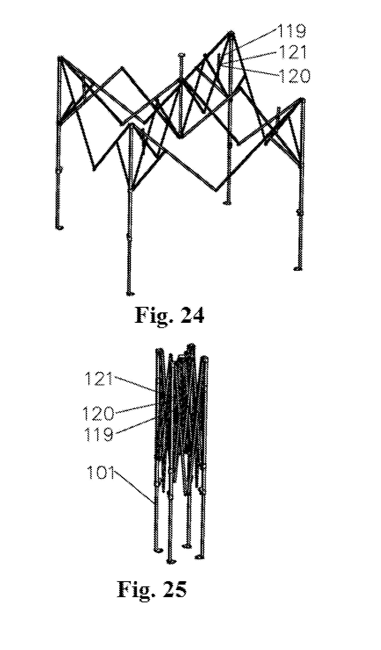
D00014
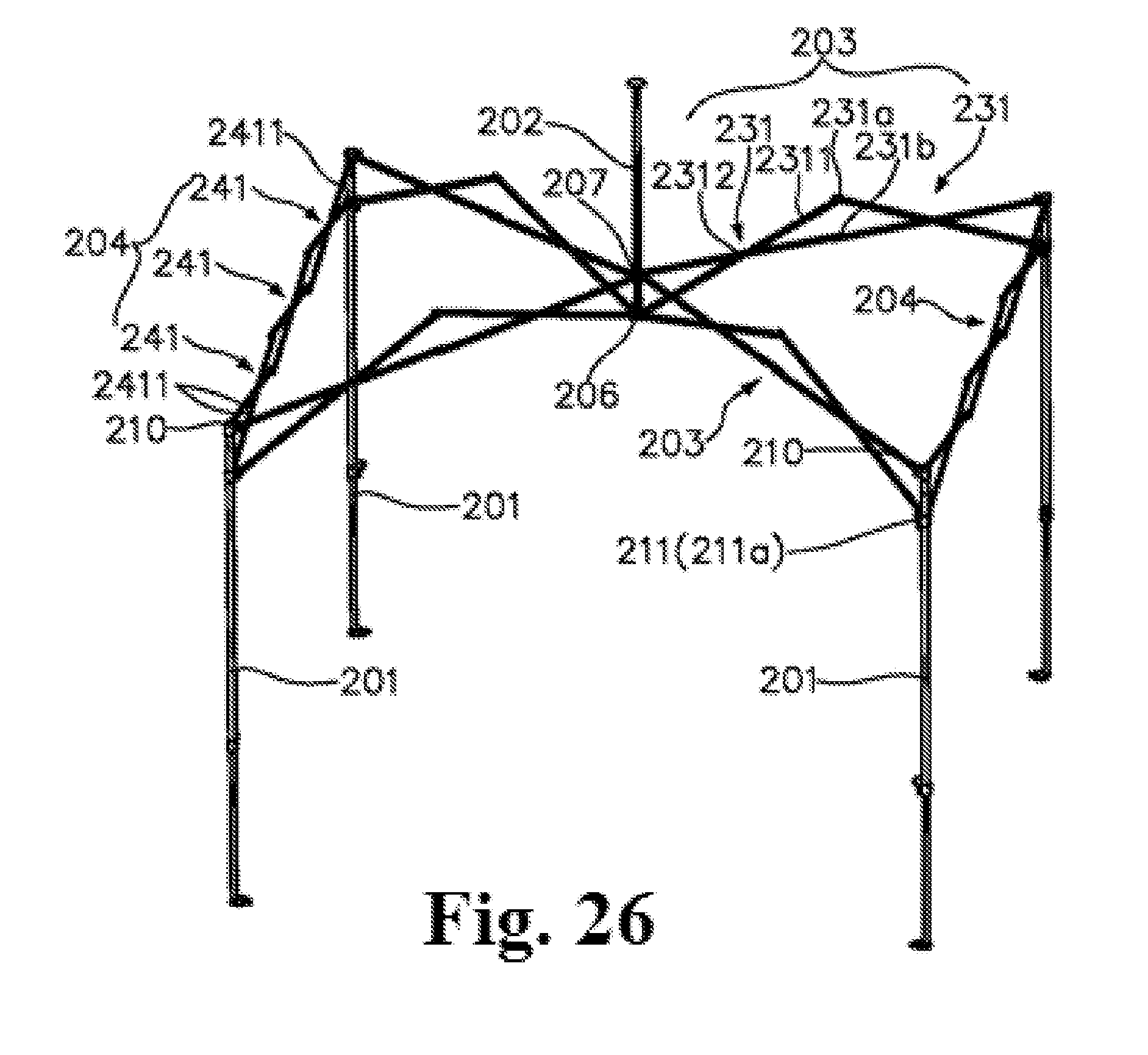
D00015
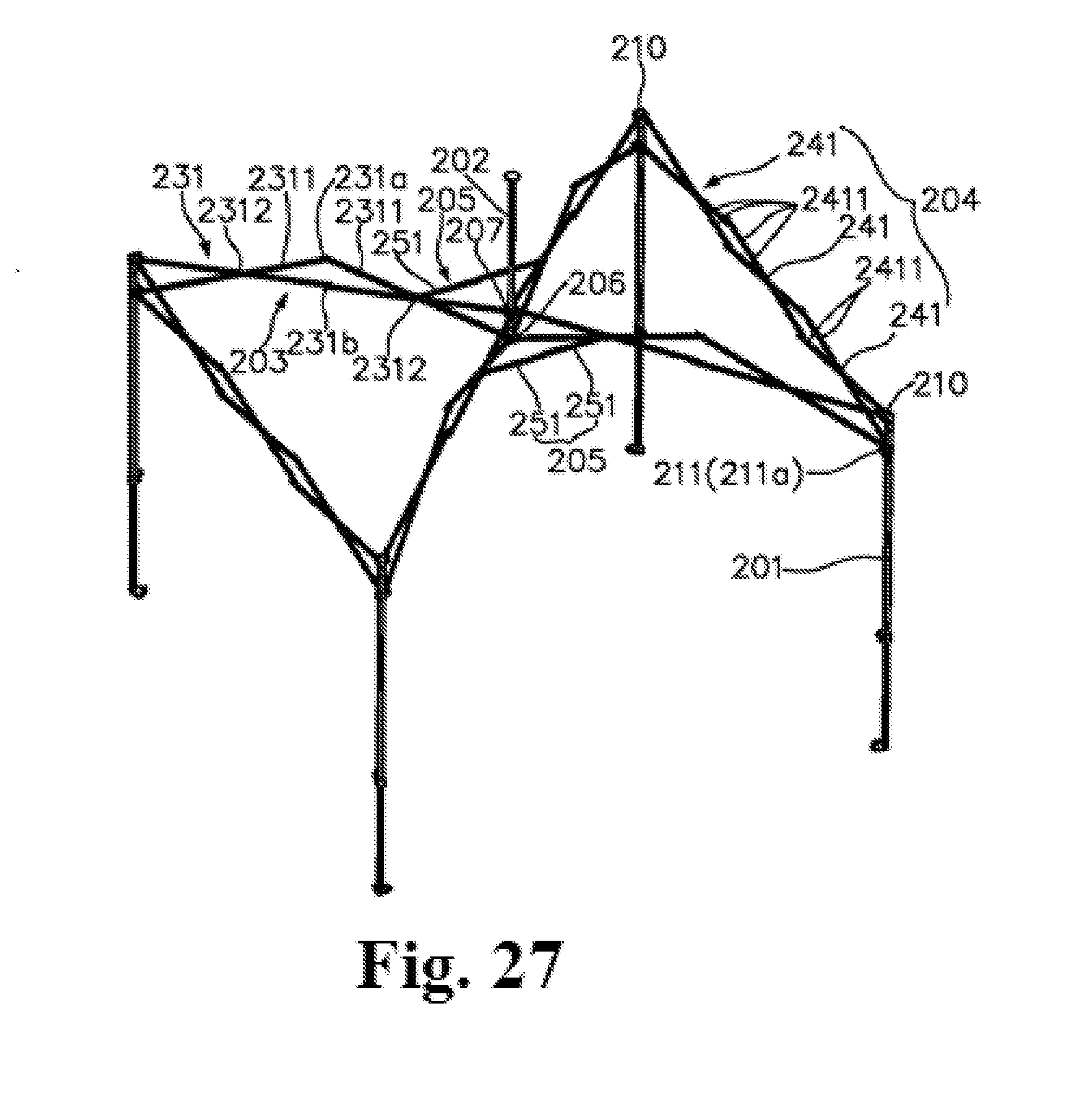
D00016
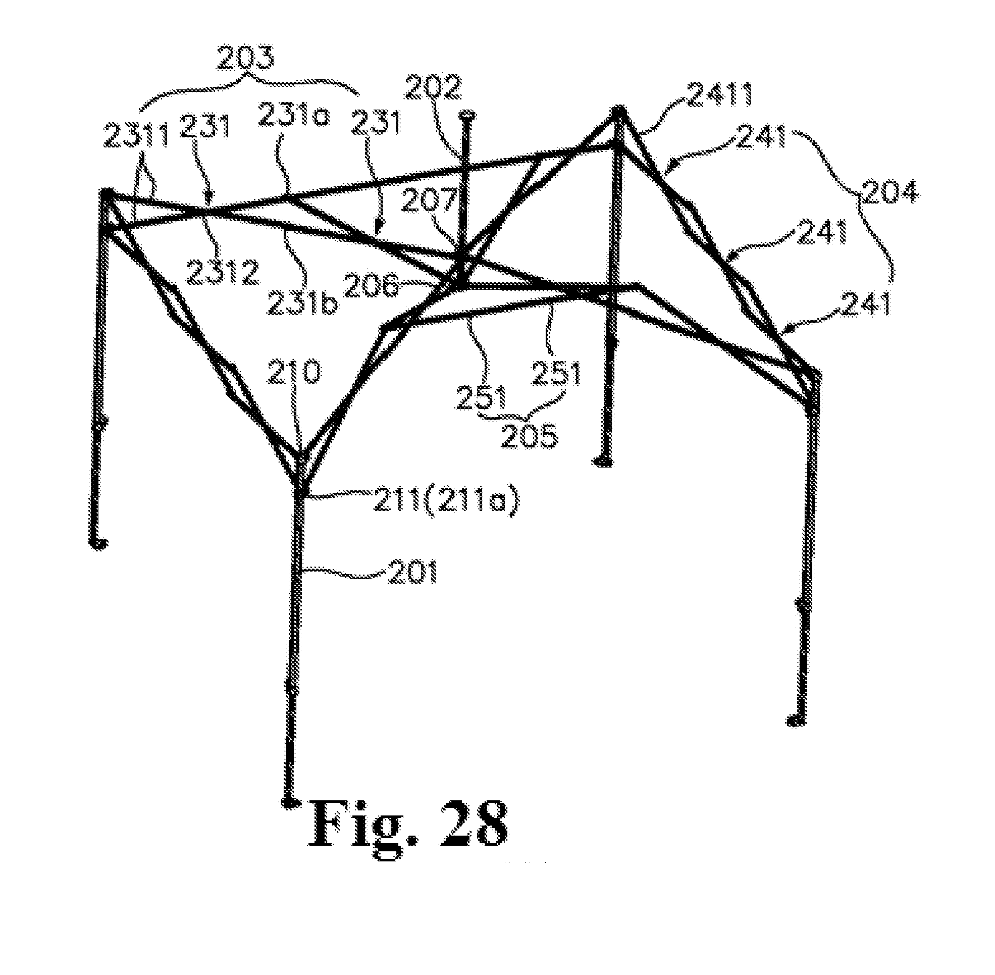
D00017
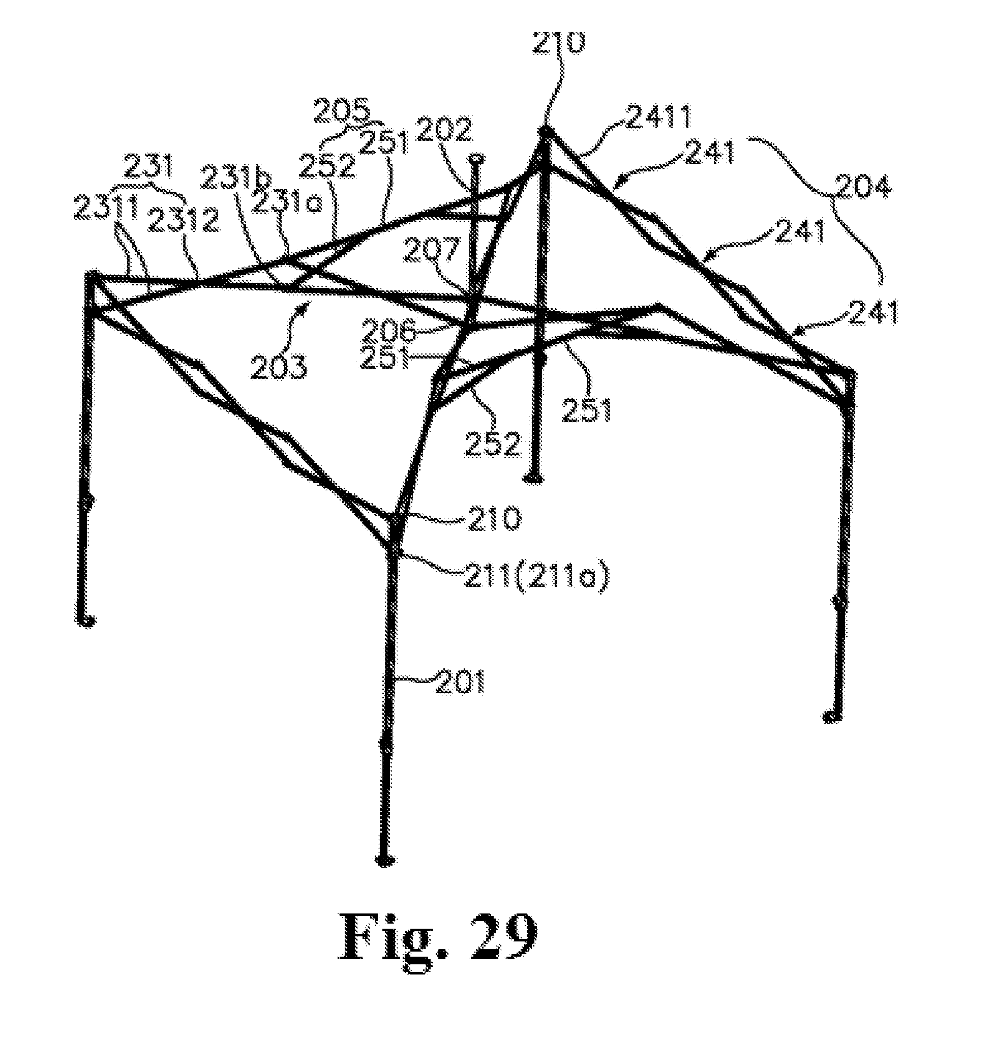
D00018

D00019
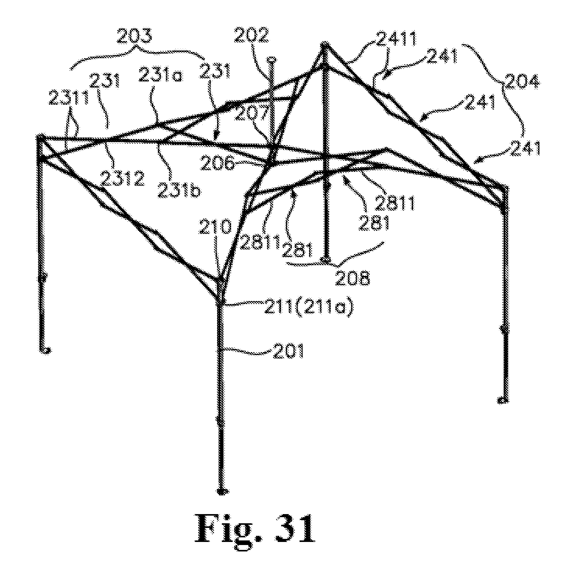
XML
uspto.report is an independent third-party trademark research tool that is not affiliated, endorsed, or sponsored by the United States Patent and Trademark Office (USPTO) or any other governmental organization. The information provided by uspto.report is based on publicly available data at the time of writing and is intended for informational purposes only.
While we strive to provide accurate and up-to-date information, we do not guarantee the accuracy, completeness, reliability, or suitability of the information displayed on this site. The use of this site is at your own risk. Any reliance you place on such information is therefore strictly at your own risk.
All official trademark data, including owner information, should be verified by visiting the official USPTO website at www.uspto.gov. This site is not intended to replace professional legal advice and should not be used as a substitute for consulting with a legal professional who is knowledgeable about trademark law.