Set Of Profile Sections For The Construction Of Walls, Panels And Angle Sections In Thermoplastic
LAURINDO; Ilmar
U.S. patent application number 14/441790 was filed with the patent office on 2015-12-31 for set of profile sections for the construction of walls, panels and angle sections in thermoplastic. This patent application is currently assigned to Ilmar LAURINDO. The applicant listed for this patent is Laurindo ILMAR. Invention is credited to Ilmar LAURINDO.
| Application Number | 20150376891 14/441790 |
| Document ID | / |
| Family ID | 50683847 |
| Filed Date | 2015-12-31 |


| United States Patent Application | 20150376891 |
| Kind Code | A1 |
| LAURINDO; Ilmar | December 31, 2015 |
SET OF PROFILE SECTIONS FOR THE CONSTRUCTION OF WALLS, PANELS AND ANGLE SECTIONS IN THERMOPLASTIC
Abstract
Set of profile sections for the construction of walls, panels and angle sections in thermoplastic, which is a set of components in the form of a profile section, extruded from PVC-type semi-rigid or similar material, and each component has a male and a female recess along the generatrix of the profile section, and these are joined to form assemblies that constitute articles for industrial use, such as walls, cladding for existing walls, roofing, panels, doors, windows, enclosures, balconies, partitions, bus stops, telephone kiosks, bath panels, screens, etc.
| Inventors: | LAURINDO; Ilmar; (FLORIANOPOLIS, BR) | ||||||||||
| Applicant: |
|
||||||||||
|---|---|---|---|---|---|---|---|---|---|---|---|
| Assignee: | LAURINDO; Ilmar Florianopolis BR |
||||||||||
| Family ID: | 50683847 | ||||||||||
| Appl. No.: | 14/441790 | ||||||||||
| Filed: | September 10, 2013 | ||||||||||
| PCT Filed: | September 10, 2013 | ||||||||||
| PCT NO: | PCT/BR2013/000361 | ||||||||||
| 371 Date: | August 9, 2015 |
| Current U.S. Class: | 52/588.1 |
| Current CPC Class: | E04B 1/28 20130101; E04F 13/072 20130101; E04F 13/0864 20130101; E04B 1/12 20130101; E04B 1/38 20130101; E04F 13/18 20130101 |
| International Class: | E04B 1/28 20060101 E04B001/28; E04F 13/072 20060101 E04F013/072; E04F 13/18 20060101 E04F013/18; E04B 1/38 20060101 E04B001/38 |
Foreign Application Data
| Date | Code | Application Number |
|---|---|---|
| Nov 8, 2012 | BR | 20 2012 028578 4 |
Claims
1- SET OF PROFILE SECTIONS FOR THE CONSTRUCTION OF WALLS, PANELS AND ANGLE SECTIONS IN THERMOPLASTIC, characterized in that a set of parts, profile extrusion type, which have notches in the male and female type, along their surfaces, wherein the workpiece (01) having straight section as a rectangle (as a rack shelves) with 10 (ten) female type fittings, the fittings (1 and 2) serve to engage the rear end of another profile the same way. Fittings (3, 5, 6, 7, 8, 10, 11 and 13) serve to receive the fitting parts 02, 03 and 04. Of the grooves, male type, (14 and 15) serve to engage the top of another profile of same. Of the beams (4, 9 and 12) serve to generate contraction providing mechanical strength to the profile, creating even, hollow chambers in the same for the installation of Styrofoam blocks increasing the thermal and acoustic insulation.
2- THE SET OF PROFILE SECTIONS FOR THE CONSTRUCTION OF WALLS, PANELS AND ANGLE SECTIONS IN THERMOPLASTIC, according to claim 1 characterized by having the workpiece (02) having the straight rod-shaped section, has 4 male type fittings, the fittings (17, 19, 20 and 21) serve to connect the side edges of the workpiece 01. From the tips (16 and 22) serve to fit another profile similarly to prevent water infiltration. Wall (18) defines the profile shape, which in this case forms a wall paneling.
3- THE SET OF PROFILE SECTIONS FOR THE CONSTRUCTION OF WALLS, PANELS AND ANGLE SECTIONS IN THERMOPLASTIC according to claim 1, characterized by having a part (03) having the straight rod-shaped section, has notches 04 shaped hanger, the fittings (24, 25, 26 and 29) serve to connect extremities 23 and 27) serve to fit another profile similarly to prevent water infiltration. The wall (28) defines the profile shape, which in this case forms a straight wall.
4- THE SET OF PROFILE SECTIONS FOR THE CONSTRUCTION OF WALLS, PANELS AND ANGLE SECTIONS IN THERMOPLASTIC, according to claim 1 characterized by having the part (04) having a straight section rod-shaped, has 4 male type fittings, fittings (31 33, 35 and 36) serve to connect the side edges of the workpiece 01. The tip (30) serves to engage the other profile in a same way to avoid water infiltration. The walls (32 and 34) define the shape of the profile, which in this case forms a straight wall with negatives.
5- THE SET OF PROFILE SECTIONS FOR THE CONSTRUCTION OF WALLS, PANELS AND ANGLE SECTIONS IN THERMOPLASTIC according to claim 1 characterized by having the workpiece (05) having a straight shaped section "F" type with two female sockets (37 and 38) which serve to connect parts 02, 03, 04, creating coating on walls, existing panels and roof replacing conventional tile. From the wall (39) serves for the fastening screws.
6- THE SET OF PROFILE SECTIONS FOR THE CONSTRUCTION OF WALLS, PANELS AND ANGLE SECTIONS IN THERMOPLASTIC according to claim 1 characterized by having the workpiece (06) having a straight section a "U" with six female type fittings, the fittings (40 and 42) serve to connect the male part 01. Fittings (43, 44, 45 and 46) serve to connect the male type fittings parts 02, 03, 04.
7- THE SET OF PROFILE SECTIONS FOR THE CONSTRUCTION OF WALLS, PANELS AND ANGLE SECTIONS IN THERMOPLASTIC according to claim 1 characterized by having the workpiece (07) having a straight shaped section "E" has four corners. The tip (47) serves to engage the chafer an opening. The ends (48 and 52) serve for fixing with double-sided. The parts (50 and 51) serve as a finishing detail, because it is a foot wheel or a view of opening.
8- THE SET OF PROFILE SECTIONS FOR THE CONSTRUCTION OF WALLS, PANELS AND ANGLE SECTIONS IN THERMOPLASTIC according to claim 1 characterized by having the workpiece (08) having a straight shaped section rail has eight female type fittings. Fittings (54, 55, 56, 57 and 58) serve to engage sealing strips. Fitting (59) serves to engage a rail room. The fitter (53 and 60) serve to fit the view of finish.
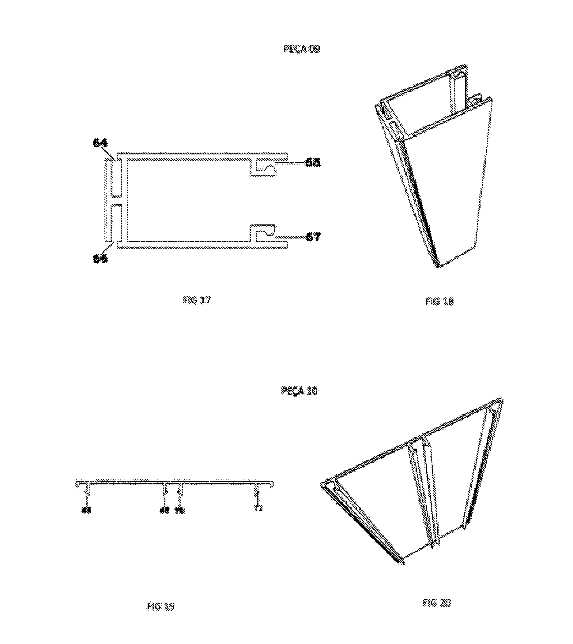
9- THE SET OF PROFILE SECTIONS FOR THE CONSTRUCTION OF WALLS, PANELS AND ANGLE SECTIONS IN THERMOPLASTIC according to claim 1 characterized by having the workpiece (09) having a straight section in "U" type has four female fittings. Fittings (64 and 66) serve to fit the pieces holding a glass lining or Venetian. Fittings (65 and 67) serve to receive the piece of closure and profile finish.
10- THE SET OF PROFILE SECTIONS FOR THE CONSTRUCTION OF WALLS, PANELS AND ANGLE SECTIONS IN THERMOPLASTIC according to claim 1 characterized by having the workpiece (10) having a straight shaped section hanger has four slots male type. Fittings (68, 69, 71 and 71) serve to connect the piece 08.
11- THE SET OF PROFILE SECTIONS FOR THE CONSTRUCTION OF WALLS, PANELS AND ANGLE SECTIONS IN THERMOPLASTIC according to claim 1 characterized by having a part (11) has key-shaped straight section has a female type fitting. Fitting (72) serves to fit sealing brush. Fitting male type (73) serves to connect the piece 08.
12- THE SET OF PROFILE SECTIONS FOR THE CONSTRUCTION OF WALLS, PANELS AND ANGLE SECTIONS IN THERMOPLASTIC according to claim 1, characterized by having the part piece (12) having straight section shaped "C" having two fittings type male. Fittings 74 and 75 serve to connect to the piece 09.
13- THE SET OF PROFILE SECTIONS FOR THE CONSTRUCTION OF WALLS, PANELS AND ANGLE SECTIONS IN THERMOPLASTIC according to claim 1 characterized by having a (13) having a straight section in the form of "U" has a male type fitting. Fitting (76) serves to connect the piece 09.
14- THE SET OF PROFILE SECTIONS FOR THE CONSTRUCTION OF WALLS, PANELS AND ANGLE SECTIONS IN THERMOPLASTIC according to claim 1 characterized by having the workpiece (14) having a straight shaped section "n" has a male type fitting. Fitting (77) serves to connect the piece 09.
15- SET OF PROFILE SECTIONS FOR THE CONSTRUCTION OF WALLS, PANELS AND ANGLE SECTIONS IN THERMOPLASTIC according to claim 1 characterized by having the workpiece (15) having a straight shaped section of two "H" type has four female fittings. The sockets (78, 79, 80 and 81) serve to connect up the parts 02, 03, 04.
Description
[0001] The present patent for a utility model refers to a set of rigid sections with low resilience extruded from plastic, which are fitted to each other to develop walls, cladding for existing walls, roofing, panels, doors, windows, enclosures, balconies, partitions, bus stops, telephone kiosks, bath panels, screens, etc.
[0002] The profiled extrusion sections have variable length and are fitted to each other in a male-female system.
[0003] The kinds of materials used for machining such set of extrusion sections are: PVC, PP, PS, PLASTIC, NYLON, ALUMINUM, ETC.
[0004] The unique characteristics between a wall for the erection of a building as existing in the market today and this set of extrusion parts is the substitution of the use of materials such as: masonry (bricks, sand, cement, lime, etc.), cardboard plaster, cement plates, wood, etc., as conventionally used in civil architecture, pre-molded materials, steel frame and wood frame. Said set will provide for the construction of a wall eliminating these materials, using just PVC or another thermoplastic material, clicking one part above the other, horizontally (piling them up), using steel beams and columns as a structural part of a cover or even the floor, thus enabling the construction with quicker handwork and at lower cost than the processes as previously mentioned, not comprising resistance and safety. They offer the advantages of better thermal and acoustic isolation and resistance against storms, also offering easy maintenance for the substitution of sections and project modification (future reforms), as originated from this set of extrusion sections. To better understand the set of sections, drawings of individual sections and a drawing of a few examples of the industrial application of a group of sections conveniently fit to each other are presented.
[0005] FIGS. 1 and 2 show a cut design in isometric perspective of the section (1) having a straight rectangular-shaped section (as a shelf rack) with 10 (ten) female fittings, of which two (1 and 2) serve to fit the back end of another profile with the same shape. The fittings (3, 5, 6, 7, 8, 10, 11 and 13) serve to receive the fitting of the sections 2, 3 and 4. Male fittings (14 and 15) serve to fit the upper part of another profile with the same shape. The crossbars (4, 9 and 12) serve to generate contraction, providing mechanical resistance to the profile, also creating hollow chambers inside it to install Styrofoam blocks so to enhance thermal and acoustic isolation.
[0006] FIGS. 3 and 4 show a cut design in isometric perspective of the section (2) having a straight rod-shaped section, with 4 male fittings (17, 19, 20, 21) serving to connect the side edges of the section 1. The fittings (16 and 22) serve to fit another profile with the same shape to avoid water infiltration. The wall (18) defines the shape of the profile, which, in this case, forms a wainscot wall.
[0007] FIGS. 5 and 6 show a cut design in isometric perspective of the section (3) having a straight rod-shaped section and 4 hanger-shaped fittings, which (24, 25, 26 and 29) serve to connect the side edges of the part 1. The edges (23 and 27) serve to fit another profile with the same shape, to avoid water infiltration. The wall (28) defines the shape of the profile, which, in this case, forms a straight wall.
[0008] FIGS. 7 and 8 show a cut design in isometric perspective of the section (4) having a straight rod-shaped section and four male fittings (31, 33, 35 and 36), serving to connect the side edges of the section 1. The edge (30) serves to fit another profile with the same shape to avoid water infiltration. The walls (32 and 34) define the shape of the profile, which, in this case, forms a straight wall with negatives.
[0009] FIGS. 9 and 10 show a cut design in isometric perspective of the section (5) having a straight "F"-shaped section with two female fittings (37 and 38) serving to connect the parts 2, 3 and 4, thus creating cladding on the walls, already existing panels and roofs, substituting conventional tiles. The wall (39) serves to fix screws.
[0010] FIGS. 11 and 12 show a cut design in isometric perspective of the section (6) having a straight "U"-shaped section with six female fittings, two of which (40 and 42) serve to connect male fittings of the section 1. The other fittings (43, 44, 45 and 46) serve to connect male fittings of the sections 2, 3 and 4.
[0011] FIGS. 13 and 14 show a cut design in isometric perspective of the part (7) having a straight "E"-shaped section having four edges. One edge (47) serves to fit an opening. The other edges (48 and 52) are for double-face fitting. Grooves (50 and 51) serve as a finishing detail, since they are a skirting or opening view.
[0012] FIGS. 15 and 16 show a cut design in isometric perspective of the section (8) with a straight trail-shaped section, having eight female fittings. The fittings (54, 55, 56, 57 and 58) serve to fit sealing screws. The fitting (59) serves to fit a fourth rail. The fittings (53 and 60) serve to fit the finishing view.
[0013] FIGS. 17 and 18 show a cut design in isometric perspective of the section (9) having a straight "U"-shaped section having four female fittings. The fittings (64 and 66) serve to fit the parts fixing a glass, lining or blind. Fittings (65 and 67) serve to receive the closing part and profile finishing.
[0014] FIGS. 19 and 20 show a cut design in isometric perspective of the section (10) having a straight hanger-shaped section with four male fittings. The fittings (68, 69, 70 and 71) serve to connect the section 8.
[0015] FIGS. 21 and 22 show a cut design in isometric perspective of the section (11) having a straight key-shaped section with a female fitting. The fitting (72) serves to fit a sealing brush. The male fitting (73) serves to connect the section 8.
[0016] FIGS. 23 and 24 show a cut design in isometric perspective of the section (12) having a straight "C"-shaped section with two male fittings. The fittings (74 and 75) serve to connect the section 9.
[0017] FIGS. 25 and 26 show a cut design in isometric perspective of the section (13) having a straight "L"-shaped section with a male fitting. The fitting (76) serves to connect the section 9.
[0018] FIGS. 27 and 28 show a cut design in isometric perspective of the section (14) having a straight "n"-shaped section with a male fitting. The fitting (77) serves to connect the section 9.
[0019] FIGS. 29 and 30 show a cut design in isometric perspective of the section (15) having a straight double "H"-shaped section with four female fittings. The fittings (78, 79, 80 and 81) serve to connect the sections 2, 3 and 4.
* * * * *
D00000
D00001
D00002
D00003
D00004
D00005
D00006
D00007
D00008
XML
uspto.report is an independent third-party trademark research tool that is not affiliated, endorsed, or sponsored by the United States Patent and Trademark Office (USPTO) or any other governmental organization. The information provided by uspto.report is based on publicly available data at the time of writing and is intended for informational purposes only.
While we strive to provide accurate and up-to-date information, we do not guarantee the accuracy, completeness, reliability, or suitability of the information displayed on this site. The use of this site is at your own risk. Any reliance you place on such information is therefore strictly at your own risk.
All official trademark data, including owner information, should be verified by visiting the official USPTO website at www.uspto.gov. This site is not intended to replace professional legal advice and should not be used as a substitute for consulting with a legal professional who is knowledgeable about trademark law.