Sink With Undercounter Hand Drying Apparatus
Moe; David
U.S. patent application number 14/737845 was filed with the patent office on 2015-12-31 for sink with undercounter hand drying apparatus. The applicant listed for this patent is David Moe. Invention is credited to David Moe.
| Application Number | 20150376881 14/737845 |
| Document ID | / |
| Family ID | 54929924 |
| Filed Date | 2015-12-31 |


| United States Patent Application | 20150376881 |
| Kind Code | A1 |
| Moe; David | December 31, 2015 |
SINK WITH UNDERCOUNTER HAND DRYING APPARATUS
Abstract
A vanity unit with hand dryer includes a casement having a top, a front and a back. A basin having a rim is carried by the casement with the rim adjacent the top. A space is defined below the casement top and the basin, and an aperture is formed proximate the rim of the basin toward the front of the casement in communication with the space below the top and the basin. A faucet is carried by the casement intermediate the basin and the back, and a hand drying assembly supplies air through the aperture from the space.
| Inventors: | Moe; David; (Scottsdale, AZ) | ||||||||||
| Applicant: |
|
||||||||||
|---|---|---|---|---|---|---|---|---|---|---|---|
| Family ID: | 54929924 | ||||||||||
| Appl. No.: | 14/737845 | ||||||||||
| Filed: | June 12, 2015 |
Related U.S. Patent Documents
| Application Number | Filing Date | Patent Number | ||
|---|---|---|---|---|
| 62017785 | Jun 26, 2014 | |||
| Current U.S. Class: | 4/638 |
| Current CPC Class: | A47K 10/48 20130101; E03C 1/14 20130101; A47K 2210/00 20130101 |
| International Class: | E03C 1/18 20060101 E03C001/18; A47K 10/48 20060101 A47K010/48; E03C 1/04 20060101 E03C001/04 |
Claims
1. A vanity unit with hand dryer comprising: a casement having a top, a front and a back; a basin having a rim, the basin carried by the casement with the rim adjacent the top; a space defined below the casement top and the basin; an aperture formed proximate the rim of the basin toward the front of the casement in communication with the space below the top and the basin; a faucet carried by the casement intermediate the basin and the back; and a hand drying assembly supplying air through the aperture from the space.
2. A vanity unit as claimed in claim 1 wherein the aperture directs air toward the back of the casement.
3. A vanity unit as claimed in claim 2 wherein the aperture is provided between the rim of the basin and the top.
4. A vanity unit as claimed in claim 1 further including a proximity sensor mounted proximate the aperture for activating the hand drying assembly.
5. A vanity unit as claimed in claim 1 wherein the hand drying assembly comprises: an air supply system; and an air supply conduit having an end coupled to the aperture and an opposing end coupled to the air supply system.
6. A vanity unit as claimed in claim 4 wherein the air supply system includes an air drying unit for generating an airflow and the air supply conduit includes a manifold positioned in the space under the basin, the manifold having a nozzle end coupled to the aperture and a coupling end coupled to the air drying unit.
7. A vanity unit as claimed in claim 4 wherein the air supply system comprises: an air compressor; the air supply conduit coupled to the air compressor through a pressure regulator and a shut-off valve movable between an normal closed position and an open position; and the air supply conduit terminating in at least one air nozzle extending through the aperture.
8. A vanity unit as claimed in claim 7 wherein the air supply system further includes a compressed air storage tank coupled between the air compressor and the air supply conduit for receiving and storing compressed air.
9. A vanity unit as claimed in claim 7 wherein the air supply system further includes a filter coupled to an intake of the compressor for filtering incoming air.
10. A vanity unit as claimed in claim 7 wherein the air supply system further includes the air supply conduit including an inline air heating tube.
11. A vanity unit as claimed in claim 7 wherein the air supply system further comprises: a control unit coupled to the shut-off valve actuating the shut-off valve between the normal closed position and the open position; and a proximity sensor positioned proximate the rim of the basin and proximate the front, and coupled to the control unit, wherein the proximity sensor sends a signal to the control unit to move the shut-off valve to the open position upon sensing an object.
12. A vanity unit as claimed in claim 8 further comprising a second air supply conduit coupled between the air compressor and a second vanity unit.
13. A vanity unit with hand dryer comprising: a casement having a top, a front and a back; a basin having a rim, the basin carried by the casement with the rim adjacent the top; a space defined below the casement top and the basin; an aperture formed proximate the rim of the basin toward the front of the casement in communication with the space below the top and the basin; a faucet carried by the casement intermediate the basin and the back; a hand drying assembly supplying air through the aperture from the space, the hand drying assembly including an air supply system, and an air supply conduit having an end coupled to the aperture and an opposing end coupled to the air supply system; a proximity sensor mounted proximate the aperture for activating the hand drying assembly; and wherein the aperture directs air from the sir supply system toward the back of the casement across the basin.
14. A vanity unit as claimed in claim 13 wherein the aperture is provided between the rim of the basin and the top.
15. A vanity unit as claimed in claim 13 wherein the air supply system includes an air drying unit for generating an airflow and the air supply conduit includes a manifold positioned in the space under the basin, the manifold having a nozzle end coupled to the aperture and a coupling end coupled to the air drying unit.
16. A vanity unit as claimed in claim 13 wherein the air supply system comprises: an air compressor; a compressed air storage tank coupled to the air compressor for receiving and storing compressed air; the air supply conduit coupled to the compressed air storage tank through a pressure regulator and a shut-off valve movable between an normal closed position and an open position; the air supply conduit including an inline air heating tube having an on state and an off state; the air supply conduit terminating in at least one air nozzle extending through the aperture; a control unit coupled to the shut-off valve actuating the shut-off valve between the normal closed position and the open position and coupled to the inline air heating tube; and a proximity sensor positioned proximate the rim of the basin and proximate the front, and coupled to the control unit, wherein the proximity sensor sends a signal to the control unit to move the shut-off valve to the open position and change the inline air heating tube to the on state upon sensing an object.
17. A vanity unit as claimed in claim 16 wherein the air supply system further includes a filter coupled to an intake of the compressor for filtering incoming air.
18. A vanity unit as claimed in claim 16 further comprising a second air supply conduit coupled between the air compressor and a second vanity unit.
Description
CROSS-REFERENCE TO RELATED APPLICATION
[0001] This application claims the benefit of co-pending U.S. Provisional Application No. 62/017,785, filed 26 Jun. 2014.
FIELD OF THE INVENTION
[0002] This invention relates to lavatory fixtures.
[0003] More particularly, the present invention relates to hand drying devices.
BACKGROUND OF THE INVENTION
[0004] In the field bathroom fixtures, there have been numerous attempts to provide devices for drying hands after washing. These devices conventionally included towel dispensers and the like, which result in large amounts of waste and must be replaced frequently. Additionally, if positioned on a wall away from the basin, trails of dripping water are left to cause an untidy appearance if not dangerously slippery conditions on the flooring. To overcome these problems, air blowers were introduced which use forced air to strip water off of the hands presented to be dried. While somewhat effective in eliminating waste and requiring replacement of towels, these devices still require movement of the user from the basin to the drying device, resulting in dripping and dispersion of water. Attempts at solving this last problem include mounting an air blower next to the faucet so the hands can be dried after washing without moving. While somewhat successful, no dripping on the floor, the blowers simply expel the water off of the hands and onto the person. Additionally, these devices are aesthetically displeasing, awkward, and clutter counter space. It would be highly advantageous, therefore, to remedy the foregoing and other deficiencies inherent in the prior art.
[0005] An object of the present invention is to provide an air blowing hand dryer in association with a sink basin.
[0006] Another object of the present invention is to provide a non-obtrusive hand dryer.
[0007] Yet another object of the present invention is to provide a hand dryer which expels water away from the individual using the device.
SUMMARY OF THE INVENTION
[0008] Briefly, to achieve the desired objects and advantages of the instant invention, provided is a vanity unit with a hand dryer. The vanity unit with hand dryer includes a casement having a top, a front and a back. A basin having a rim is carried by the casement with the rim adjacent the top. A space is defined below the casement top and the basin. An aperture is formed proximate the rim of the basin toward the front of the casement in communication with the space below the top and the basin. A faucet is carried by the casement intermediate the basin and the back. A hand drying assembly supplies air through the aperture from the space. The aperture directs the supplied air toward the back of the casement across the basin. A proximity sensor is mounted proximate the aperture for activating the hand drying assembly. The hand drying assembly includes an air supply system, and an air supply conduit having an end coupled to the aperture and an opposing end coupled to the air supply system.
[0009] In a specific aspect, the air supply system includes an air drying unit for generating an airflow and the air supply conduit includes a manifold positioned in the space under the basin. The manifold has a nozzle end coupled to the aperture and a coupling end coupled to the air drying unit.
[0010] In another aspect, the air supply system includes an air compressor. The air supply conduit is coupled to the air compressor through a pressure regulator and a shut-off valve movable between a normal closed position and an open position. The air supply conduit terminates in at least one air nozzle extending through the aperture.
BRIEF DESCRIPTION OF THE DRAWINGS
[0011] The foregoing and further and more specific objects and advantages of the invention will become readily apparent to those skilled in the art from the following detailed description of a preferred embodiment thereof, taken in conjunction with the drawings in which:
[0012] FIG. 1 is a partial sectional side view of a vanity unit with hand drying apparatus according to the present invention;
[0013] FIG. 2 is a top plan view of the vanity unit of FIG. 1;
[0014] FIG. 3 is a perspective view of a vanity unit with hand drying apparatus and an air intake assembly according to the present invention;
[0015] FIG. 4 is a sectional side view of the vanity unit of FIG. 3;
[0016] FIG. 5 is a partial sectional side view of a vanity unit having a self rim china bowl sink with hand drying apparatus;
[0017] FIG. 6 is a partial sectional side view of a vanity unit having a self rim stainless steel sink with hand drying apparatus;
[0018] FIG. 7 is a partial sectional side view of a vanity unit having an under-mounted sink with hand drying apparatus;
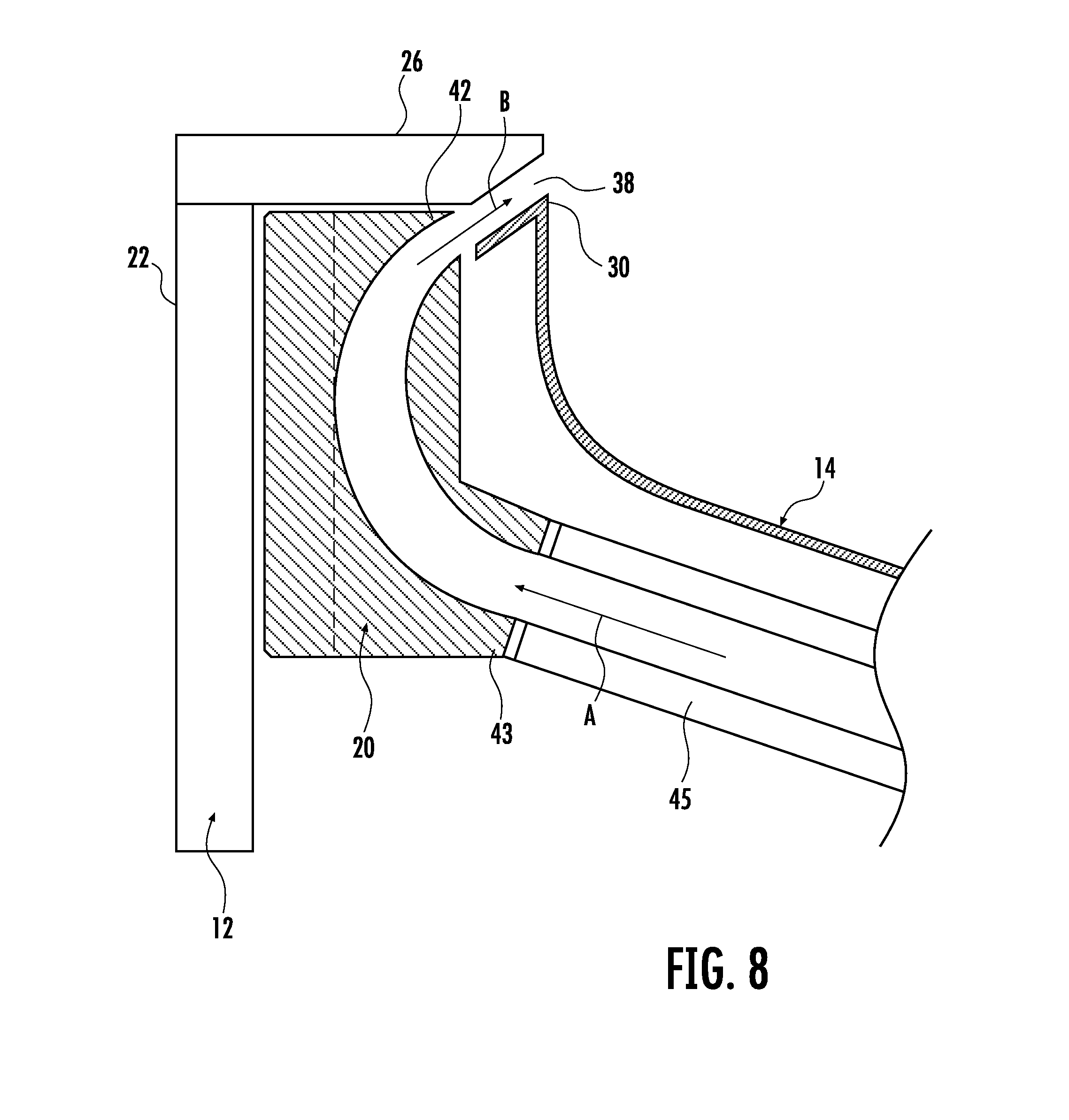
[0019] FIG. 8 is a partial sectional side view of a vanity unit having an under-mounted stainless steel sink with hand drying apparatus;
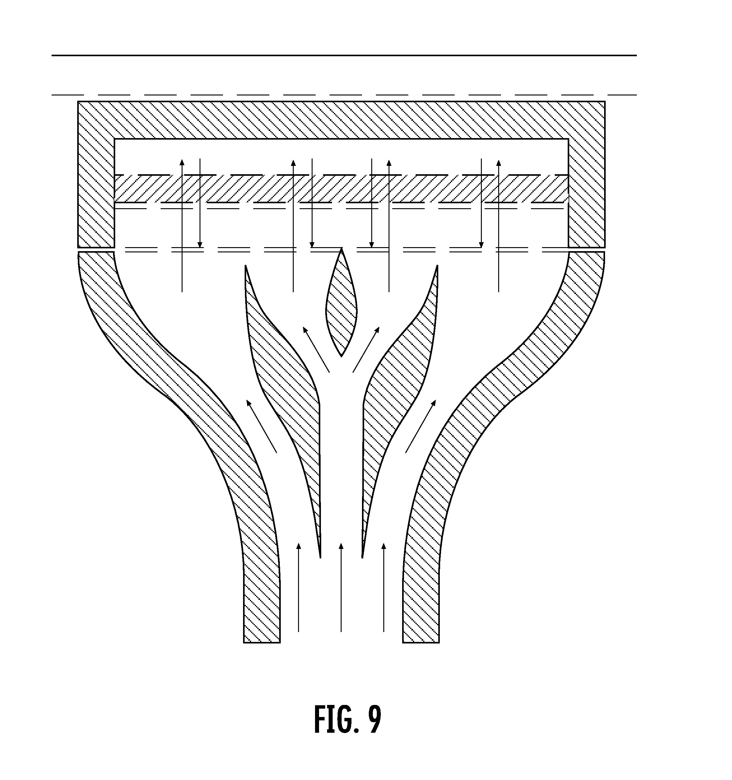
[0020] FIG. 9 is a sectional view of a manifold according to the present invention; and
[0021] FIG. 10 is a simplified schematic of a compressed air system according to the present invention.
DETAILED DESCRIPTION OF A PREFERRED EMBODIMENT
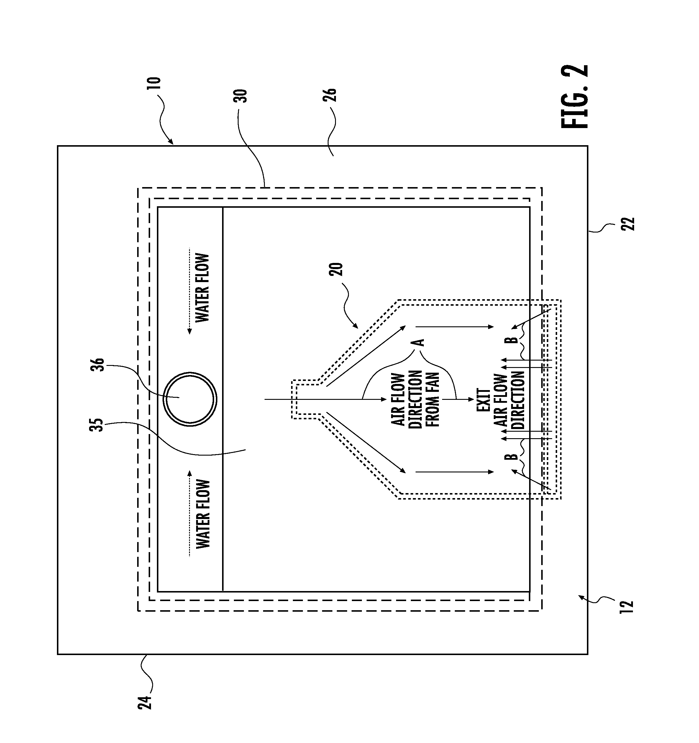
[0022] Turning now to the drawings in which like reference characters indicate corresponding elements throughout the several views, attention is directed to FIGS. 1 and 2 which illustrate a vanity unit 10 including a casement 12, a basin 14, a faucet 16, and a hand drying assembly 20. In this description, casement 12 is intended to include the structures of a vanity unit that support a basin. These structures can vary greatly. In this embodiment, casement 12 includes a front 22, a back 24 and a top 26. Casement 12 can be a conventional vanity casement, well known to those skilled in the art, including a top and cabinetry. For purposes of this invention, casement 12 can also be a simple arrangement wherein top 26 is supported in some manner without accompanying cabinetry, such as the arrangements found in public restrooms and the like. Furthermore, top 26 can include substantially any kind of counter top such as tile, metal, solid surface, natural stone, engineered stone, and the like. It will also be understood that in some circumstances, such as pedestal sinks and some trough sinks, and the like, the expanded surfaces around the basin of the sink are considered top 26 of casement 12, and front 22 and back 24 are sometimes integrally formed with basin 14.
[0023] In this embodiment, basin 14 is carried by top 26 of casement 12 intermediate front 22 and back 24. Faucet 16 is carried by top 26 (which can be part of basin 14) intermediate basin 14 and back 24. It will be understood that for purposes of orientation the terms "front" and "back" are used to designate the position relative a user. The "front" designates the side of the casement a user stands at for use, and the term "back" is the side opposite the user, where the faucet is positioned. Depending on the basin type employed, top 26 may overly, underlie or be integrally formed with a rim 30 of basin 14. In the embodiment illustrated, basin 14 includes rim 30 underlying vanity top 26, has upright sidewalls 33 and a bottom 35. Bottom 35 is sloped to a drain 36 formed therein, proximate sidewall 33 and adjacent back 24 of casement 12. The placement of basin 14 within casement 12 is variable, and can be adjusted to the depth of substantially any vanity casement as with any conventional basin. Basin 14 can be a conventional basin in some instances, as will be described presently, and can be modified for use in this specific application which will also be described presently.
[0024] Still referring to FIGS. 1 and 2, in this embodiment, basin 14 is under-mounted to top 26. At rim 30 of basin 14 proximate front 22, an aperture 38 is provided between rim 30 and top 26. Aperture 38 is in communication with a space 31 defined by casement 12 below casement top 26 and basin 14. This aperture is preferably elongate along a portion of rim 30 at front 22, and can be created by removing material from rim 30, removing material from top 26, forming basin 14 with a depression in rim 30 at the appropriate location in front, or the like. Thus, a conventional basin 14 can be employed, a modified basin 14 can be employed or a newly fabricated basin 14 ban be used. Self rim sinks, those overlying top 26, will require manufacturers to modify the sink to include an aperture formed therein. For sinks with overflow openings in the front, aperture 38 can be split and positioned on both sides thereof or limited to one side or the other.
[0025] Hand drying assembly 20 supplies air through aperture 38, and in this embodiment includes a manifold 40 having a nozzle end 42 and a coupling end 43, an air supply conduit 45 and an air supply system consisting of an air drying unit 46 in this preferred embodiment. Air drying unit 46 is a unit generating an airflow which may be heated or unheated, and can be substantially any air drying unit. Unit 46 is positioned proximate vanity casement 12, and preferably under top 26 proximate back 24. Air supply conduit 45 is preferably a hose coupled to unit 46 and extending to manifold 40. Conduit 45 is coupled to coupling end 43 and supplies air from unit 46. It will be understood that positioning of manifold 40 is important to the invention, while positioning of unit 46 is not critical, but preferably is mounted out of sight and out of the way. With specific reference to FIG. 2, manifold 40 is positioned proximate bottom 35, under basin 14, and with nozzle end 42 positioned to direct air flow shown as arrowed lines A to aperture 38. Thus, Nozzle end 42 is positioned under top 26 in front of basin 14, rearward of front 22. In this manner, air is directed from aperture 38 in a direction indicated by arrowed lines B, rearwardly over basin 14. In the preferred embodiment, the air is directed upwardly at approximately a 35 degree angle. While this has been found to be the optimum angle, other angles will also work. An individual will be able to air dry hands while remaining before the basin. Any droplets or other dislodged water will be directed away from the individual and generally into basin 14. With additional reference to FIG. 9, manifold 40 can include diverters and other structures to uniformly deliver air to a user over the width of an elongated aperture 38.
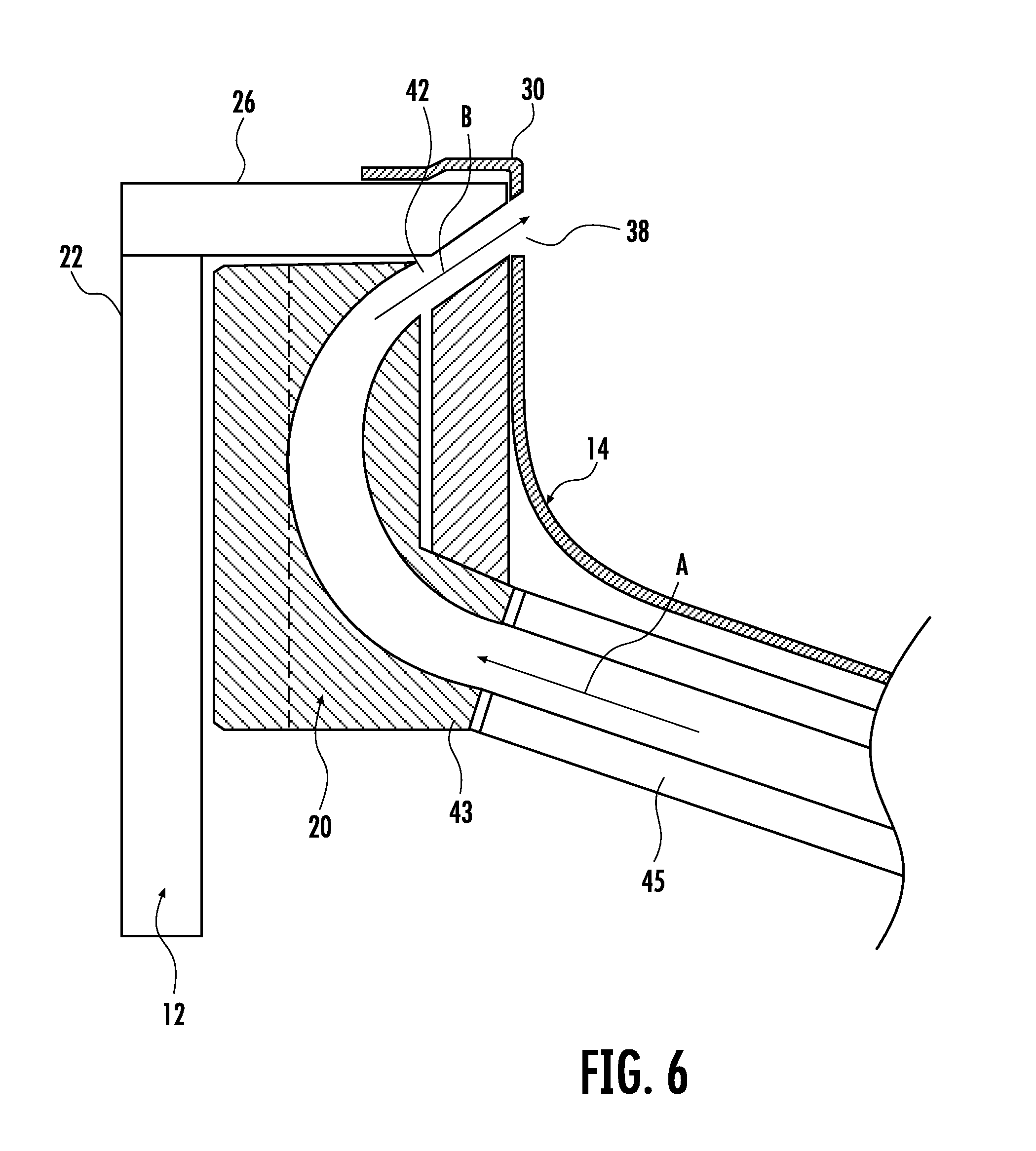
[0026] With momentary reference to FIGS. 5-8, various types of basins are illustrated. FIGS. 5 and 6 illustrate self rim basins with rims 30 overlying top 26. In these instances, aperture 38 is formed in the front of basin 14 below rim 30, so as to align with nozzle 42. FIGS. 7 and 8 illustrate under-mount basins with rims 30 underlying top 26. In these instances, aperture 38 is formed in the juncture between top 26 and rim 30. One or the other, or both are beveled or grooved to form aperture 38 therebetween. In the case of a stainless steel basin as illustrated in FIG. 8, rim 30 can bent down to form the desired shape. In all cases the junction of top 26 and rim 30 are shaped to form aperture 38 align with nozzle 42.
[0027] A control process will limit hand drying assembly 20 to specific operating times. For example, when faucet 16 is on and water is running into basin 14, hand drying assembly 20 will remain off. Motion sensors 54 or other switches can be employed to detect motion proximate basin 14, and turn off assembly 20 if there is no motion or activity, or a certain amount of time has expired. Air flow from unit 46 can be adjusted by controls 50 at unit 46 as can the temperature of the air generated. Additional features can include heating elements 52 at nozzle end 42 to further heat the air. It will be understood that a single unit 46 can be used to supply air to multiple sinks if desired, and if the airflow generated is sufficient.
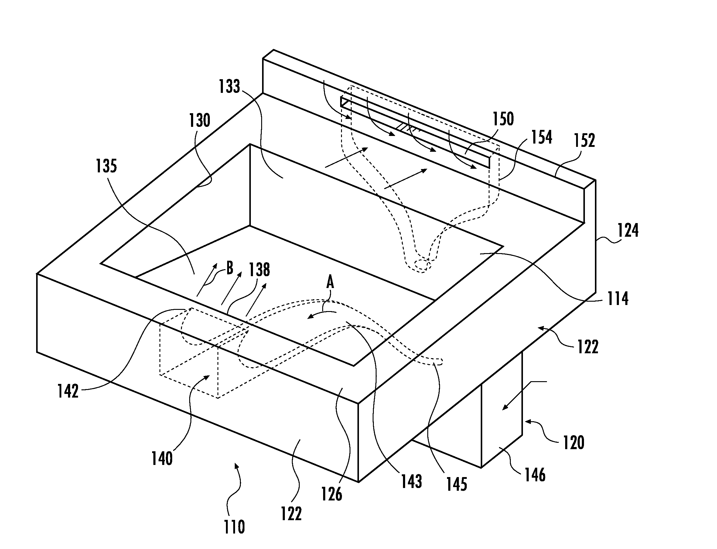
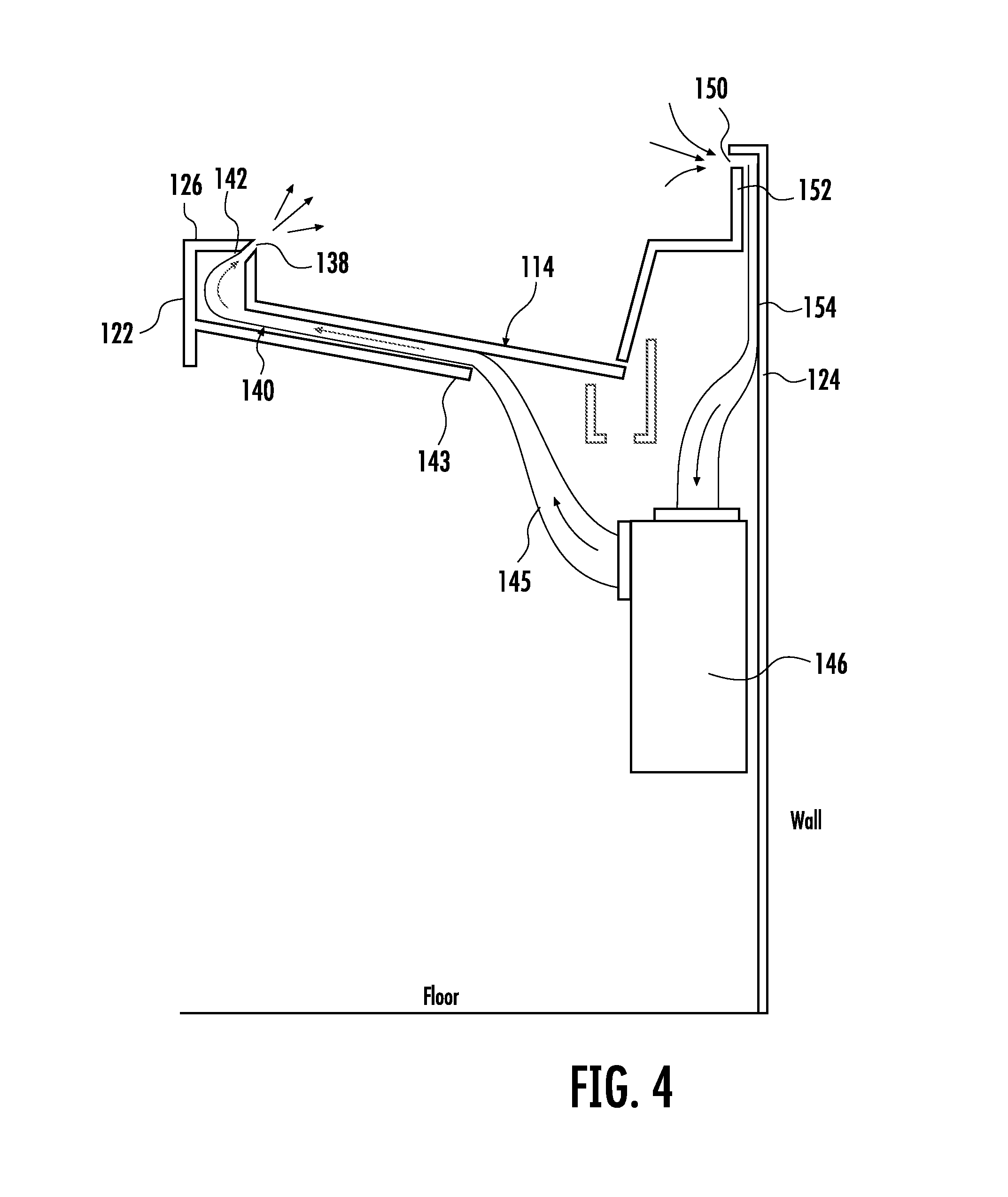
[0028] Turning now to FIGS. 3 and 4, a vanity unit 110 including a casement 112, a basin 114, and a hand drying assembly 120, is illustrated. In this embodiment, hand drying assembly 120 includes a manifold 140 having a nozzle end 142 and a coupling end 143, an air supply conduit 145 and an air drying unit 146 as with the previous embodiment. While basin 114 is illustrated as a unitary element, casement 112 is integrated into basin 114 and includes a front 122, a back 124 and a top 126. In the embodiment illustrated, basin 114 includes rim 130 concurrent with top 126, has upright sidewalls 133 and a bottom 135. In this embodiment, an aperture 138 is provided at the junction of rim 130 and top 126. This aperture is preferably elongate along a portion of rim 130 at front 122.
[0029] Additionally, in the present embodiment, hand drying assembly 120 includes an air intake slot 150 formed proximate a back splash 152 extending upwardly from top 126 proximate back 124. A return air duct 154 extends from intake slot 150 to air drying unit 146. It will be understood that air intake slot 150 can also be formed in stop 126 if desired, particularly when a back splash 152 is absent.
[0030] Vanity unit 10 and 110 can be provided with a hand drying assembly 20 and 120 employing a different air supply system. While the previous embodiments employ an air blower 46 and 146, the air blower can be replaced with a compressed air system generally designated 310. Turning to FIG. 10, compressed air system 310 includes an air compressor 312 and a compressed air storage tank 314 which can be located anywhere, but are preferably located outside the room containing the vanity unit. In operation, air is drawn through a fine air filter 315 and into air compressor 312 where it is compressed to approximately 130 psi+/-, and stored in compressed air storage tank 314. Tank 314 is preferably of approximately 80 gallon capacity, although this will depend upon the number of units serviced and the volume of use. One or more air supply tubes 316 are coupled to storage tank 314, each to supply compressed air to a corresponding basin 318. A single compressor and storage tank can be employed to service multiple basins, or a single basin 318, as illustrated. It will be understood that basin 318 can be substantially any basin carried by a casement 320 having a back side 330 and a front side 332, as described previously. Basin 318 includes a rim 322, upright sidewalls 323 and a bottom 325. Bottom 325 is sloped to a drain 326 formed therein. A faucet 328 is positioned at basin 318 adjacent back side 330. Back side 330 is preferably positioned against a wall through which is passed air supply tube 316.
[0031] Still referring to FIG. 10, air supply tube 316 is coupled to a pressure regulator 340 which is set to reduce the air pressure to 20-25 psi and then a shut-off valve 342. Shut off valve 342 is preferably a 12 volt DC activated solenoid valve. Valve 342 is moved between a normal closed position preventing air flow and an open position to allow passage of compressed air. Air tube 316 is then coupled to an inline air heating tube 344 (e.g. AHP series from Omegalux) having a normal off state and an on state. In the on state the passing air is heated and passed on through two air nozzles 346 located at the rim 322 of a sink basin 318 adjacent front side 332. Nozzles 346 are positioned to direct compressed air across basin 318 toward rear side 330. As with the previous embodiments, the nozzles can be mounted at the juncture of rim 322 and a counter top, fully in the top edge of the basin or a combination, depending on the basin type and the vanity arrangement. While a variety of nozzles can be employed hydrojet nozzles from MTM Hydro, Inc. are exemplary.
[0032] A control unit 350, consisting primarily of a control circuit board, is coupled to shut off valve 342 and controls the flow of power to valve 342 from a power source 352. When control unit 350 applies power to valve 342, valve 342 is moved from the normal closed position to the open position, and remains open until power supply is curtailed. Control unit 350 is also coupled to inline air heating tube 344 and applies power thereto changing it from the off state to the on state for heating the air passing therethrough. A proximity sensor 354 (e.g. cable/sharp GP2Y0A41SK0F analog distance sensor 4-30 cm) is mounted into rim 322 of basin 318 proximate front side 330, with a predetermined sensing distance of approximately 11/2'', although this can be adjusted as desired. Sensor 354 is coupled to control unit 350, and upon sensing a user's hands, sends a signal to control unit 350 that, in turn, provides power to valve 342 and heater tube 344, changing them from the closed position and off state, to the open position and on state, respectively. In this manner, after washing their hands, a user simply pulls the hands toward themselves and towards rim 332 to trip sensor 354 and provide warm, clean air from nozzles 346.
[0033] In the preferred embodiment, two nozzles 354 are positioned to provide shaped jets of compressed air which force water off the user's hands as the user rotates their hands around the streams of air. The water falls directly down into sink basin 318 and into drain 326. In addition, the now heated air quickly evaporates any remaining dampness. Forcing air through a specifically shaped and slight nozzle aperture allows for fine tuning the precise shape of the air stream with the corresponding correct air pressure to achieve the greatest positive effect at the hands of the user. Air blowers using integrated `blower style` vacuumed motor systems cannot generate significant pressure and are therefore trapped to comparatively large round openings or large slots and requiring medium to high volumes of air to be effective with the inherent noise pollution factor. Once the user has completed the drying process and leaves the basin, the flow of heated air automatically shuts down or shuts down after a timed interval. Control unit 350 can be used to shut down the electric switches for a number of reasons including expired preset time, no movement detected, or possible safety issues. When air pressure within tank 314 is reduced to a predetermined level, compressor 312 starts and fills tank 314 to capacity. This mechanism is mostly quiet other than during the running of the compressor, which is preferably in a remote location.
[0034] Various changes and modifications to the embodiments herein chosen for purposes of illustration will readily occur to those skilled in the art. To the extent that such modifications and variations do not depart from the spirit of the invention, they are intended to be included within the scope thereof, which is assessed only by a fair interpretation of the following claims.
* * * * *
D00000
D00001
D00002
D00003
D00004
D00005
D00006
D00007
D00008
D00009
D00010
XML
uspto.report is an independent third-party trademark research tool that is not affiliated, endorsed, or sponsored by the United States Patent and Trademark Office (USPTO) or any other governmental organization. The information provided by uspto.report is based on publicly available data at the time of writing and is intended for informational purposes only.
While we strive to provide accurate and up-to-date information, we do not guarantee the accuracy, completeness, reliability, or suitability of the information displayed on this site. The use of this site is at your own risk. Any reliance you place on such information is therefore strictly at your own risk.
All official trademark data, including owner information, should be verified by visiting the official USPTO website at www.uspto.gov. This site is not intended to replace professional legal advice and should not be used as a substitute for consulting with a legal professional who is knowledgeable about trademark law.