Heavy Duty Insulated Beverage Dispenser And Cooler
Holderness; Stephen ; et al.
U.S. patent application number 14/752034 was filed with the patent office on 2015-12-31 for heavy duty insulated beverage dispenser and cooler. The applicant listed for this patent is High Performance Coolers LLC. Invention is credited to Robert Joseph Cicero, Stephen Holderness.
| Application Number | 20150375918 14/752034 |
| Document ID | / |
| Family ID | 54929697 |
| Filed Date | 2015-12-31 |


| United States Patent Application | 20150375918 |
| Kind Code | A1 |
| Holderness; Stephen ; et al. | December 31, 2015 |
HEAVY DUTY INSULATED BEVERAGE DISPENSER AND COOLER
Abstract
Disclosed is an insulated beverage dispenser having a generally cube-shaped insulated body with an interior chamber, an open top, and an outlet adjacent a bottom of the interior chamber. It includes a removable closure member for the outlet and an insulated top hingedly connected to the body to close the open top. A guideway is located on a front outer surface of the body generally adjacent the open top and is sized and positioned to receive a securement strap extended across the body without interference with opening the top. The closure member can be a liquid dispensing valve and/or a plug. An interior surface of the lid may include a recess for receiving a spare closure member for the outlet.
| Inventors: | Holderness; Stephen; (Florence, KY) ; Cicero; Robert Joseph; (Union, KY) | ||||||||||
| Applicant: |
|
||||||||||
|---|---|---|---|---|---|---|---|---|---|---|---|
| Family ID: | 54929697 | ||||||||||
| Appl. No.: | 14/752034 | ||||||||||
| Filed: | June 26, 2015 |
Related U.S. Patent Documents
| Application Number | Filing Date | Patent Number | ||
|---|---|---|---|---|
| 62018242 | Jun 27, 2014 | |||
| Current U.S. Class: | 222/566 ; 220/592.2 |
| Current CPC Class: | F25D 3/08 20130101; F25D 29/006 20130101; A47G 23/04 20130101; A45C 13/30 20130101; B65D 25/102 20130101; F25D 2331/806 20130101; B67D 2210/00044 20130101; A45C 11/20 20130101; B65D 83/00 20130101; B65D 81/3823 20130101; B67D 3/0067 20130101 |
| International Class: | B65D 81/38 20060101 B65D081/38; B65D 83/00 20060101 B65D083/00 |
Claims
1. An insulated beverage dispenser, comprising: a generally cube-shaped insulated body having an interior chamber, an open top, and an outlet adjacent a bottom of the interior chamber; a removable closure member for the outlet; an insulated top hingedly connected to the body to close the open top; a guideway on a front outer surface of the body generally adjacent the open top that is sized and positioned to receive a securement strap extended across the body without interference with opening the top.
2. The insulated beverage dispenser of claim 1, wherein the closure member is a liquid dispensing valve.
3. The insulated beverage dispenser of claim 1, wherein the closure member is a plug.
4. The insulated beverage dispenser of claim 1, wherein an interior surface of the lid includes at least one recess for receiving a spare closure member for the outlet.
5. The insulated beverage dispenser of claim 1, wherein the body includes first and second opposite tie-down passageways.
6. The insulated beverage dispenser of claim 1, wherein the lid includes a plurality of exterior edge notches positioned to guide a tie-down strap extended across the lid.
7. The insulated beverage dispenser of claim 1, further comprising lid latches positioned to secure the lid in a closed position.
8. The insulated beverage dispenser of claim 7, wherein the lid latches extend over the guideway.
9. The insulated beverage dispenser of claim 1, further comprising left and right opposite carry handles.
10. The insulated beverage dispenser of claim 9, wherein the handles are integral with the body.
11. The insulated beverage dispenser of claim 9, wherein the handles include movable gripping portion that is extendable to a position above the lid.
Description
RELATED APPLICATION
[0001] This applications claims the benefit of and priority to U.S. Provisional Patent Application No. 62/018,242 filed Jun. 27, 2014, the entire contents and disclosure of which is incorporated herein by reference.
TECHNICAL FIELD
[0002] This invention relates to an insulated beverage dispenser and cooler constructed in a particular way to enhance its durability and utility.
BACKGROUND OF THE INVENTION
[0003] Large insulated beverage dispensers having a spigot and removable lid are known in order to provide bulk quantities of cold refreshment beverage, such as water, to a group of people or workers. Prior designs lack the durability and compact design necessary to make them suitable for extreme conditions or situations where failure could have catastrophic consequences.
SUMMARY OF THE INVENTION
[0004] The present invention provides an insulated beverage dispenser with a generally cube-shaped insulated body having an interior chamber, an open top, and an outlet adjacent a bottom of the interior chamber. It includes a removable closure member for the outlet and an insulated top hingedly connected to the body to close the open top. A guideway is provided on a front outer surface of the body generally adjacent the open top that is sized and positioned to receive a securement strap extended across the body without interference with opening the top.
[0005] The closure member may be a liquid dispensing valve and/or an interchangeable plug. An interior surface of the lid may include at least one recess for receiving a spare closure member for the outlet. The body may include first and second opposite tie-down passageways.
[0006] The lid can include lid latches positioned to secure the lid in a closed position and may include a plurality of exterior edge notches positioned to guide a tie-down strap extended across the lid. The lid latches can extend over the guideway.
[0007] The insulated beverage dispenser can include left and right opposite carry handles that are integral with the body and/or have a movable gripping portion that is extendable to a position above the lid.
[0008] Further features, aspects, benefits, and objects of the present invention may be apparent to a person skilled in the art upon examination of the following detailed description and various figures of the drawing.
BRIEF DESCRIPTION OF THE DRAWINGS
[0009] Like reference numerals are used to indicate like parts throughout the various figures of the drawings, wherein:
[0010] FIG. 1 is an isometric view of a first embodiment of a heavy duty insulated beverage dispenser according to one embodiment of the present invention;
[0011] FIG. 2 is an isometric view thereof with the lid in an open position;
[0012] FIG. 3 is a fragmentary cross sectional view taken substantially along line 3-3 of FIG. 2;
[0013] FIG. 4 is a right side plan view thereof with the rope handle in a lifted position;
[0014] FIG. 5 is an isometric view of a second embodiment; and
[0015] FIG. 6 is an isometric view thereof with the lid in an open position.
DETAILED DESCRIPTION OF THE INVENTION
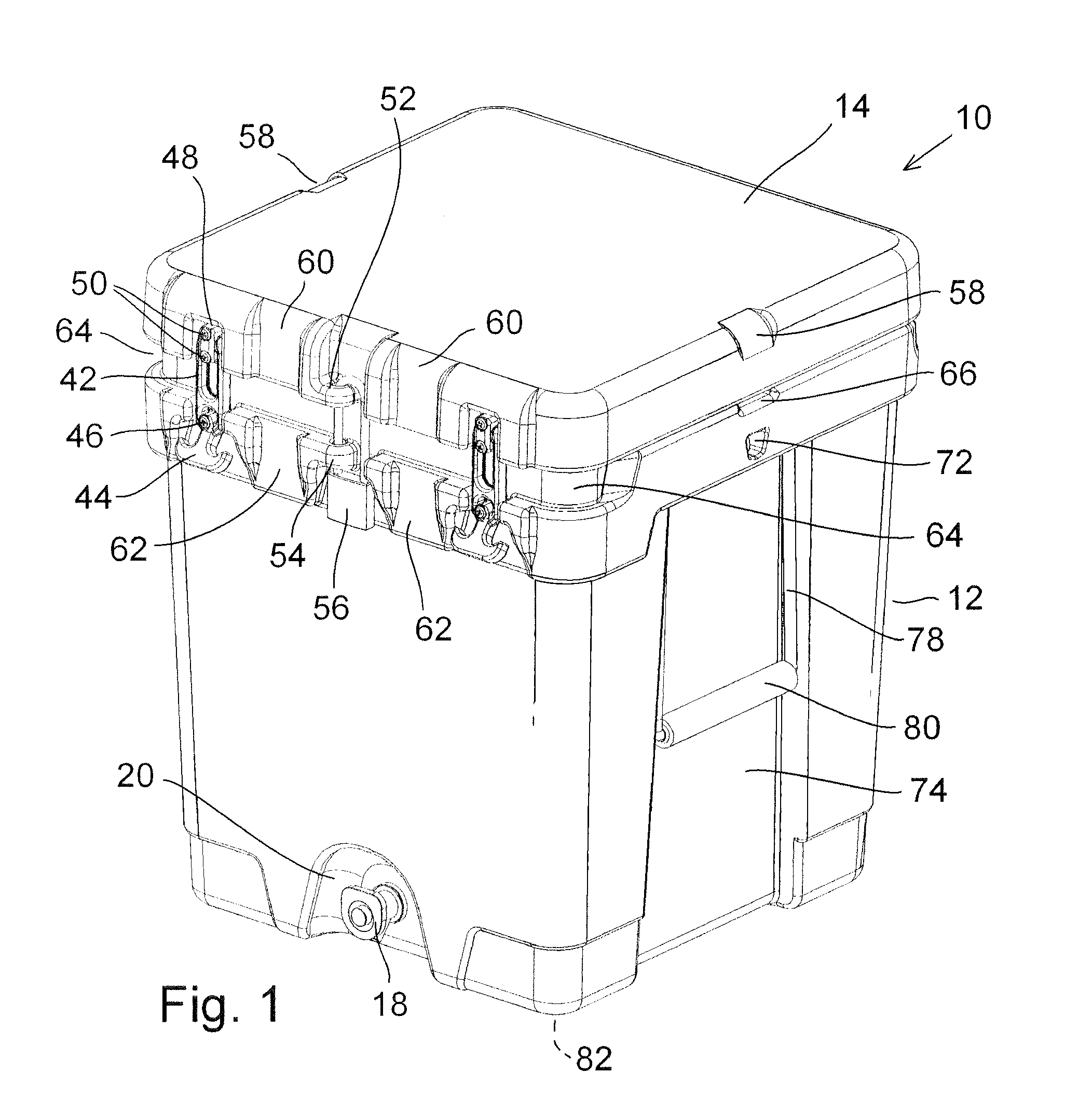
[0016] Referring now to the various figures of the drawing, and first to FIGS. 1 and 2, therein is shown at 10 a heavy duty insulated beverage dispenser and cooler unit according to a first embodiment of the invention. The illustrated unit 10 may be sized, for example, to hold approximately 40 quarts of liquid volume. In general terms, the unit 10 includes a body 12 and a lid 14 which may be pivotally attached to the body 12 by a hinge. The body 12 includes a hollow interior chamber 16. Hot or cold liquid put in the chamber 16 may be drained through an ordinary push-button spigot or valve 18 that is in fluid communication with the interior chamber 16.
[0017] The body 12 and lid 14 have spaced apart interior and exterior walls made of a durable moldable material, such as rotomolded compounded polyethylene. The space between the interior and exterior walls may be filled with an insulating material, such as polyurethane foam. The primary purpose of the unit 10 may be keeping liquids hot or cold for extended periods of time, which may be dispensed as needed through the valve 18. A large top opening allows ice to be dumped into or from the chamber 16 with ease.
[0018] According to one feature of the invention, the dispensing valve 18 may be situated in a recess 20 so that the valve 18 does not protrude beyond the front and bottom profile of the body 12. In this way, the valve 18 is protected from damage. The overall shape of the unit 10 may be relatively square, providing improved security and stability during transport of the container, while maximizing the interior capacity of the unit 10 relative to its footprint or profile. In other words, multiple units 10 or other containers, such as tool boxes, can be stacked together or placed adjacent one another with minimal wasted space compared to the common cylindrical shape found in other insulated beverage dispensers.
[0019] According to another feature of the invention, the interior wall 22 of the lid 14 may include one or more recesses 24, 26 for removably holding spare or alternative parts. For example, a first recess 24 may be sized and shaped to receive and hold a spare valve 18 for use in the event the other valve 18 fails or becomes damaged. Additionally, a second recess 26 may be sized and shaped to receivably hold a plug 28, which may be used to replace the valve 18 in the event the unit 10 is to be used as an insulated cooler rather than a beverage dispenser. Common dispenser valves 18 engage an opening in the dispenser with a threaded connection. A threaded plug 28 may be conveniently held in place by providing corresponding threads in the second recess 26.
[0020] Referring now in particular to FIG. 2, the upper edge of the body 12 may be provided with a raised annular lip or ridge 30 positioned to confront a correspondingly positioned elastomeric seal 32 installed on the interior wall 22 of the lid 12. Accordingly, the unit 10 may be provided with a water tight seal such that liquids in the interior chamber 16 will not escape even if the unit 10 is tipped or inverted.
[0021] The lid 14 may be hinged to the body 12 along a rear upper edge of the body 12 with alternating lid and body knuckles 34, 36 that have axially aligned openings sized to receive a replaceable metal rod 38. This provides an extraordinarily durable hinge, while allowing the lid 14 and body 12 to be separated for repair or replacement.
[0022] The lid 14 may be secured in a closed position by use of elastomeric draw latches 40. One end of the elastomeric latch arm 42 may be secured to the lid 14, for example, and may be stretched by using a handle portion 44 to engage the latch arm 42 with a cleat mounted in a corresponding position on the body 12. Such a closure devise is particularly durable and can survive high impact without damage, while being easily replaceable, if necessary. The latch arm 42 may be attached to the lid 14 such as with an anchor member 48 by use of screws or rivets 50. In this manner, the latch arm 42 is allowed to pivot relative to the lid 14, allowing it to be moved out of the way and not hamper easy opening and closing of the lid 14.
[0023] The unit 10 may be secured against tampering or contamination by providing a pair of aligned eyes 52, 54 on the lid 14 and body 12 to receive an elongated shank padlock 56. As shown in FIG. 1, recesses may be provided adjacent the attachment eyes 52, 54 to allow a padlock 56 to rest within the overall profile of the unit 10 without projecting outwardly therefrom where it may be susceptible to damage. Alternatively, single use ties or other tamper-evident security devices (not shown) may be used to lock the unit 10 through the eyes 52, 54 and control access.
[0024] According to another aspect of the invention, the body 12 and lid 14 may include a variety of molded openings, contours and/or indentations that facilitate utilization of strapping, lashing, or hook devices to secure the unit 10 in place to hold the unit 10 down or laterally against a support surface on a building, vehicle or support stand. For example, the lid 14 may be provided with left and right edge guide notches or indentations 58 which help hold a strap (not shown) in place without sliding when used to latch the unit 10 to a support surface below it. Alternatively, the forward edge of the lid 14 and forward upper edge of the body 12 may be provided with edge guide notches or cuts 60, 62, also sized to engage standard cargo straps that may be provided in a front-to-rear orientation.
[0025] Additional features may be provided for securing the body portion 12 of the unit 10 in a way that allows the lid 14 to be opened while the unit 10 remains securely held in place. For example, a forward upper edge of the body 12 may be provided with a transverse groove or guideway 64, also sized to receive a common cargo securement strap. This guideway or groove 64 allows such a securement strap to be fixed in place under and without interfering with either the latches 40 or padlock 56.
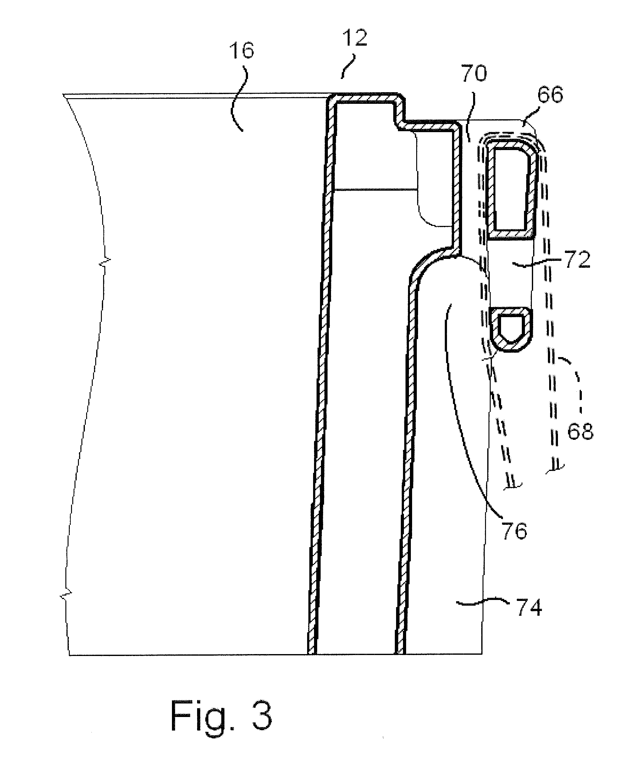
[0026] Referring now in particular to FIGS. 1 and 4, upper side edges of the body 12 may be provided with guide indentations 66 for accommodating a tie down strap 68. A vertical passageway 70 is aligned with the guide indentation 66 to accept a tie-down strap 68, as illustrated in FIG. 3. Alternatively, hook openings 72 may be provided to receive tie-down hooks, such as on the end of an elastomeric cord.
[0027] Indentations 74 in sides of the body 12 provide two functions. First, as best illustrated in FIG. 3, the indentations 74 in combination with the upper extended edge where the vertical passageway 70 and hook opening 72 may be found, provide a recess 76 for receiving the fingers of a person lifting the unit 10. Additionally, as shown in FIGS. 1, 2, 5, and 16, flexible handles made by a combination of rope 78 and a rigid grip tube 80 provide handles that fall within the side recesses 74 when at rest. The rigid tube 80 may be made with a solid core and cushioned foam exterior to provide a comfortable and secure grip. When at rest, the rope handles 78, 80 are positioned in a flush alignment with the outside edges of the body 12 in the molded indentations 74. Referring now also to FIG. 4, therein can be seen that when the rope handles 78, 80 are lifted, a grip is provided at a selected height H above the bottom of the unit 10.
[0028] Elastomeric feet 82 may be provided on the outer bottom surface of the body 12 to resist sliding movement of the unit 10 on a support surface that may be wet, angled or subject to vibration.
[0029] Referring now to FIGS. 5 and 6, therein is shown an insulated beverage dispenser and cooler 84 according to an alternate embodiment of the invention. This alternate embodiment may be of smaller capacity than the previously described unit 10, such as having an interior chamber 16 of approximately 20 quarts volume. Other than the overall size and capacity of the unit 84, it differs from the previously-described unit 10 minimally, in that it does not include rope handles or eyes for receiving a padlock. With those exceptions, like reference numerals are used to indicate corresponding parts and features throughout the use of this second embodiment.
[0030] While one embodiment of the present invention has been described in detail, it should be apparent that modifications and variations thereto are possible, all of which fall within the true spirit and scope of the invention. Therefore, the foregoing is intended only to be illustrative of the principles of the invention. Further, since numerous modifications and changes will readily occur to those skilled in the art, it is not intended to limit the invention to the exact construction and operation shown and described. Accordingly, all suitable modifications and equivalents may be included and considered to fall within the scope of the invention.
* * * * *
D00000
D00001
D00002
D00003
D00004
D00005
D00006
XML
uspto.report is an independent third-party trademark research tool that is not affiliated, endorsed, or sponsored by the United States Patent and Trademark Office (USPTO) or any other governmental organization. The information provided by uspto.report is based on publicly available data at the time of writing and is intended for informational purposes only.
While we strive to provide accurate and up-to-date information, we do not guarantee the accuracy, completeness, reliability, or suitability of the information displayed on this site. The use of this site is at your own risk. Any reliance you place on such information is therefore strictly at your own risk.
All official trademark data, including owner information, should be verified by visiting the official USPTO website at www.uspto.gov. This site is not intended to replace professional legal advice and should not be used as a substitute for consulting with a legal professional who is knowledgeable about trademark law.