Lid Assembly And Method
Cohen Bissu; Abraham
U.S. patent application number 14/721335 was filed with the patent office on 2015-12-31 for lid assembly and method. The applicant listed for this patent is Abraham Cohen Bissu. Invention is credited to Abraham Cohen Bissu.
| Application Number | 20150375910 14/721335 |
| Document ID | / |
| Family ID | 54929693 |
| Filed Date | 2015-12-31 |


View All Diagrams
| United States Patent Application | 20150375910 |
| Kind Code | A1 |
| Cohen Bissu; Abraham | December 31, 2015 |
LID ASSEMBLY AND METHOD
Abstract
A resealable lid assembly may provide a substantially resealable lid for a container. The resealable lid assembly may include a lid assembly, external lid layer, valve lid layer, pivot, tab, outlet, vent, tab slot, flow seal and vent seal. A method to provide a substantially resealable lid for a container using the resealable lid assembly is also provided.
| Inventors: | Cohen Bissu; Abraham; (Sunny Isles Beach, FL) | ||||||||||
| Applicant: |
|
||||||||||
|---|---|---|---|---|---|---|---|---|---|---|---|
| Family ID: | 54929693 | ||||||||||
| Appl. No.: | 14/721335 | ||||||||||
| Filed: | May 26, 2015 |
Related U.S. Patent Documents
| Application Number | Filing Date | Patent Number | ||
|---|---|---|---|---|
| 62016948 | Jun 25, 2014 | |||
| 62023999 | Jul 14, 2014 | |||
| Current U.S. Class: | 53/484 ; 220/254.4 |
| Current CPC Class: | B65D 47/265 20130101; B65D 17/4014 20180101; B65D 51/20 20130101 |
| International Class: | B65D 47/26 20060101 B65D047/26; B65D 51/18 20060101 B65D051/18; B65D 43/18 20060101 B65D043/18 |
Claims
1. A lid assembly installable on a container comprising: an external lid layer; a valve lid layer operatively connected to the external lid layer via a pivot; a tab operatively connected to the valve lid layer; and a sealant applied to at least part of the lid assembly; wherein the valve lid layer is rotatable via the pivot; wherein the lid assembly is substantially continuously variable between a closed configuration and an opened configuration via the tab.
2. The lid assembly of claim 1, further comprising: an outer engagement channel of the external lid layer; and an outer engagement rim of the valve lid layer receivable by the outer engagement channel; wherein the outer engagement rim is locatable at least partially within the outer engagement channel to substantially seal a space enclosable by the lid assembly.
3. The lid assembly of claim 1, wherein the tab is configurable between a tab up position and a tab down position.
4. The lid assembly of claim 3, wherein the valve lid layer is substantially immobilized while the tab is in the tab down position, and wherein the valve lid layer is substantially rotatable via the pivot while the tab is in the tab up position.
5. The lid assembly of claim 1, wherein the external lid layer further comprises: a flow outlet hole; and a tab slot hole.
6. The lid assembly of claim 1, wherein the valve lid layer further comprises: a flow upset; and a tab slot upset.
7. The lid assembly of claim 1: wherein the external lid layer comprises a flow outlet hole; wherein the valve lid layer comprises a flow upset; and wherein the valve lid layer is rotatable via the pivot to vary a flow aperture.
8. The lid assembly of claim 7: wherein the external lid layer further comprises a tab slot hole; wherein the valve lid layer further comprises a tab slot upset; and wherein the tab is operatively connected to the valve lid layer approximately at the tab slot upset; wherein the tab is at least partially locatable within a length of the tab slot hole; and wherein moving the tab within at least part of the length of the tab slot hole causes the valve lid layer to rotate via the pivot and vary the flow aperture.
9. The lid assembly of claim 1: wherein the external lid layer further comprises a vent hole; wherein the valve lid layer further comprises a vent upset; wherein a vent aperture is substantially opened while the lid assembly is in the opened configuration; and wherein the vent aperture is substantially closed while the lid assembly is in the closed configuration.
10. A lid assembly installable on a container comprising: an external lid layer comprising a flow outlet hole and a tab slot hole; a valve lid layer comprising a flow upset and a tab slot upset; a tab operatively connected to the valve lid layer approximately at the tab slot upset and at least partially locatable about a length of the tab slot hole; and a pivot operatively connecting the external lid layer and the valve lid layer; wherein the lid assembly is substantially continuously variable between a closed configuration and an opened configuration; wherein moving the tab at least partially within the length of the tab slot hole causes the valve lid layer to rotate via the pivot to vary a flow aperture; wherein the tab is configurable between a tab up position and a tab down position; wherein the valve lid layer is substantially immobilized while the tab is in the tab down position; wherein the valve lid layer is substantially rotatable via the pivot while the tab is in the tab up position.
11. The lid assembly of claim 10, wherein the tab slot upset comprises a dimple to receive at least part of the tab while oriented approximately in the tab up position.
12. The lid assembly of claim 10, further comprising: an outer engagement channel of the external lid layer; and an outer engagement rim of the valve lid layer receivable by the outer engagement channel; wherein the outer engagement rim is locatable at least partially within the outer engagement channel to substantially seal a space enclosable by the lid assembly.
13. The lid assembly of claim 10, wherein the external lid layer further comprises a vent hole; wherein the valve lid layer further comprises a vent upset; wherein a vent aperture is substantially opened while the lid assembly is in the opened configuration; and wherein the vent aperture is substantially closed while the lid assembly is in the closed configuration.
14. The lid assembly of claim 10, further comprising a sealant at least partially applied to the valve lid layer.
15. A method of reversibly sealing a container via a lid assembly, the lid assembly comprising an external lid layer, a valve lid layer, a tab, and a pivot, the method comprising: (a) configuring the tab in a tab up position to enable rotation of the valve lid layer, the tab being operatively connected to the valve lid layer; (b) moving the tab within a length of a tab slot hole of the external lid layer, causing the valve lid layer to be rotated via the pivot; and (c) altering the lid assembly between a closed configuration and an opened configuration via rotation of the valve lid layer to vary a flow aperture.
16. The method of claim 15, further comprising after step (c): (d) configuring the tab in a tab down position to substantially immobilize the valve lid layer; wherein the tab is operatively connected to the valve lid layer.
17. The method of claim 15, wherein the lid assembly is substantially continuously variable between the closed configuration and the opened configuration.
18. The method of claim 15, wherein the pivot operatively connects the external lid layer and the valve lid layer, wherein the tab is operatively connected to the valve lid layer approximately at a tab slot upset of the valve lid layer, and wherein the tab is movable at least partially about the length of the tab slot hole of the external lid layer.
19. The method of claim 15: wherein the external lid layer comprises a vent hole; wherein the valve lid layer comprises a vent upset; wherein a vent aperture is substantially opened while the lid assembly is in the opened configuration; and wherein the vent aperture is substantially closed while the lid assembly is in the closed configuration.
20. The method of claim 15, wherein the lid assembly further comprises a sealant at least partially applied to the valve lid layer.
Description
CROSS-REFERENCE TO RELATED APPLICATION
[0001] This application claims the priority from U.S. provisional patent application Ser. No. 62/016,948 filed Jun. 25, 2014 and U.S. provisional patent application Ser. No. 62/023,999 filed Jul. 14, 2014. The foregoing applications are incorporated in their entirety herein by reference.
FIELD OF THE INVENTION
[0002] The present invention relates to a lid assembly. More particularly, the invention relates to provide a substantially resealable lid assembly for a container.
BACKGROUND
[0003] Containers are typically manufactured and sold with a "one-time-use" lid assembly. At the time of use, the user will pull up on a tab with his/her finger or otherwise puncture the lid assembly, providing access to the interior space of the container. In containers with tabs, for example, beverage cans, the lower portion of the tab pushes a partially sheared portion of the lid inward toward the fluid-holding portion of the can. As the partially sheared portion of the lid is pushed into the can, the material bends and yields, thus allowing the metal lid to be permanently bent and displaced to provide a flow outlet for the dispensation of liquid from the can and through the flow outlet in the lid. While the tab remains attached to the lid by means of a rivet and the partially sheared portion of the lid remains displaced in the fluid-holding portion of the can, the user typically bends the tab back to a position close to its initial state, such as the its state prior to pulling up on the tab. In this state, the can is considered to be "open" or "opened." In no practical way can the partially sheared portion of the lid be bent back upward and resealed to the portion of the lid from which it was sheared.
[0004] Previous generations of cans used removable tabs that ended up being tossed on the ground as trash. This was potentially dangerous for those walking around without shoes, small children (choking/swallowing hazard), and animals.
[0005] Typical motions like walking with an open can of soda in your hand or driving a car with an open soda can in the cup holder may often provide sufficient movement of the fluid in the opened can to cause the fluid to splash around and eventually involuntarily exit the can through the flow outlet. The fluid may damage clothing, upholstery, electronics, and more.
[0006] Containers, including beverage containers, typically fail to provide ventilation to the container as the fluid is being dispensed from the container. As fluid is poured from a container, the fluid leaving is replaced by an equal volume of air (i.e. the "bloop, bloop, bloop . . . " sound as soda is poured from a can). Without ventilation, the volumetric replacement of fluid with air agitates the carbonated beverage, increases the head (foam) in the cup into which the beverage is being poured, may increase the likelihood of splatter (i.e. damage to clothing, upholstery, electronics, etc.), and prolongs the time it takes to empty an entire can in a single pour.
[0007] Furthermore, no currently existing known container designs that provide for a structure to close the can after it has been opened in order to reduce the likelihood of splashing, spilling, etc. while walking, driving, or doing other physical activities that create motion of the liquid in the can. Some aftermarket devices exist that allow the user to close a soda can after it has been opened, but these products are not directly integrated into the soda can itself and can be cumbersome to operate. These externally applied products are also choking/swallowing hazards for small children and animals.
[0008] Therefore, a need exists to solve the deficiencies present in the prior art. What is needed is a lid fixable to a container that can be resealed. What is needed is a lid that can be easily altered between an opened state and a closed state. What is needed is a substantially resealable lid with a valve to increase fluid flow dynamics. What is needed is a method of manipulating the lid of a container between a sealed and an unsealed state.
SUMMARY
[0009] An aspect of the invention advantageously provides a lid fixable to a container that can be resealed. An aspect of the invention advantageously provides a lid that can be easily altered between an opened state and a closed state. An aspect of the invention advantageously provides a substantially resealable lid with a valve to increase fluid flow dynamics. An aspect of the invention advantageously provides a method of manipulating the lid of a container between a sealed and an unsealed state.
[0010] The lid assembly detailed in this disclosure remedies the deficiencies of current container lid assemblies by providing the mechanical functionality to temporarily close a container after it has been opened for the first time.
[0011] In an embodiment of this disclosure, after the container is opened for the first time, a valve lid layer can be rotated in either a clockwise or counter clockwise direction to open or close the container. The valve lid layer can be also be partially rotated between opened and closed orientations to provide for a partially opened state. The direction of rotation required to open or close the can may be dependent on the physical location of some of the various components within the lid assembly.
[0012] Accordingly, the disclosure may feature a lid assembly installable on a container. The lid assembly may include an external lid layer, valve lid layer, a tab, and optionally a sealant. The valve lid layer may be operatively connected to the external lid layer via a pivot. The tab may be operatively connected to the valve lid layer. The sealant may be applied to at least part of the lid assembly. The valve lid layer may be rotatable via the pivot. The lid assembly may be substantially continuously variable between a closed configuration and an opened configuration via the tab.
[0013] In another aspect, the lid assembly may include an outer engagement channel of the external lid layer and an outer engagement rim of the valve lid layer receivable by the outer engagement channel. The outer engagement rim may be locatable at least partially within the outer engagement channel to substantially seal a space enclosable by the lid assembly.
[0014] In another aspect, the tab may be configurable between a tab up position and a tab down position.
[0015] In another aspect, the valve lid layer may be substantially immobilized while the tab is in the tab down position. Conversely, the valve lid layer may be substantially rotatable via the pivot while the tab is in the tab up position.
[0016] In another aspect, the external lid layer may further include a flow outlet hole and a tab slot hole.
[0017] In another aspect the valve lid layer may further include a flow upset and a tab slot upset.
[0018] In another aspect the external lid layer may include a flow outlet hole. The valve lid layer may include a flow upset. The valve lid layer may be rotatable via the pivot to vary a flow aperture.
[0019] In another aspect, the external lid layer may further include a tab slot hole. The valve lid layer may further include a tab slot upset. The tab may be operatively connected to the valve lid layer approximately at the tab slot upset. The tab may be at least partially locatable within a length of the tab slot hole. Moving the tab within at least part of the length of the tab slot hole may cause the valve lid layer to rotate via the pivot and vary the flow aperture.
[0020] In another aspect, the external lid layer may include a vent hole. The valve lid layer may include a vent upset. A vent aperture may be substantially opened while the lid assembly is in the opened configuration. The vent aperture may be substantially closed while the lid assembly is in the closed configuration.
[0021] According to an embodiment of the present invention, a lid assembly installable on a container is provided that may include an external lid layer, a valve lid layer, a tab, and a pivot. The external lid layer may include a flow outlet hole and a tab slot hole. The valve lid layer may include a flow upset and a tab slot upset. The tab may be operatively connected to the valve lid layer approximately at the tab slot upset and may be at least partially locatable about a length of the tab slot hole. The pivot may be operatively connecting the external lid layer and the valve lid layer. The lid assembly may be substantially continuously variable between a closed configuration and an opened configuration. Moving the tab at least partially within the length of the tab slot hole causes the valve lid layer to rotate via the pivot to vary a flow aperture. The tab may be configurable between a tab up position and a tab down position. The valve lid layer may be substantially immobilized while the tab is in the tab down position. The valve lid layer may be substantially rotatable via the pivot while the tab is in the tab up position.
[0022] In another aspect, the tab slot upset may include a dimple to receive at least part of the tab while oriented approximately in the tab up position.
[0023] In another aspect, the lid assembly may additionally include an outer engagement channel of the external lid layer and an outer engagement rim of the valve lid layer receivable by the outer engagement channel. The outer engagement rim may be locatable at least partially within the outer engagement channel to substantially seal a space enclosable by the lid assembly.
[0024] In another aspect, the external lid layer may further include a vent hole. The valve lid layer may additionally include a vent upset. A vent aperture may be substantially opened while the lid assembly is in the opened configuration. The vent aperture may be substantially closed while the lid assembly is in the closed configuration.
[0025] In another aspect, the lid assembly may additionally include a sealant at least partially applied to the valve lid layer.
[0026] According to an embodiment of the present invention, a method is provided for of reversibly sealing a container via a lid assembly. The lid assembly may include an external lid layer, a valve lid layer, a tab, and a pivot. The method may include (a) configuring the tab in a tab up position to enable rotation of the valve lid layer, the tab being operatively connected to the valve lid layer. The method may additionally include (b) moving the tab within a length of a tab slot hole of the external lid layer, causing the valve lid layer to be rotated via the pivot. The method may further include (c) altering the lid assembly between a closed configuration and an opened configuration via rotation of the valve lid layer to vary a flow aperture.
[0027] In another aspect, the method may include after step (c), (d) configuring the tab in a tab down position to substantially immobilize the valve lid layer. The tab may be operatively connected to the valve lid layer.
[0028] In another aspect, the lid assembly may be substantially continuously variable between the closed configuration and the opened configuration.
[0029] In another aspect, the pivot may operatively connect the external lid layer and the valve lid layer. The tab may be operatively connected to the valve lid layer approximately at a tab slot upset of the valve lid layer. The tab may be movable at least partially about the length of the tab slot hole of the external lid layer.
[0030] In another aspect, the external lid layer may include a vent hole. The valve lid layer may include a vent upset. A vent aperture may be substantially opened while the lid assembly is in the opened configuration. The vent aperture may be substantially closed while the lid assembly is in the closed configuration.
[0031] In another aspect, the lid assembly may additionally include a sealant at least partially applied to the valve lid layer.
[0032] Terms and expressions used throughout this disclosure are to be interpreted broadly. Terms are intended to be understood respective to the definitions provided by this specification. Technical dictionaries and common meanings understood within the applicable art are intended to supplement these definitions. In instances where no suitable definition can be determined from the specification or technical dictionaries, such terms should be understood according to their plain and common meaning. However, any definitions provided by the specification will govern above all other sources.
[0033] Various objects, features, aspects, and advantages of the invention described by this disclosure will become more apparent from the following detailed description, along with the accompanying drawings in which like numerals represent like components.
BRIEF DESCRIPTION OF THE DRAWINGS
[0034] FIG. 1 is a perspective view of a lid assembly, according to an embodiment of this disclosure.
[0035] FIG. 2 is a cross-section view of a lid assembly, according to an embodiment of this disclosure.
[0036] FIG. 3 is an exploded perspective view of a lid assembly, according to an embodiment of this disclosure.
[0037] FIG. 4 is a top plan view of a lid assembly in a closed state, according to an embodiment of this disclosure.
[0038] FIG. 5 is a top plan view of a lid assembly in an opened state, according to an embodiment of this disclosure.
[0039] FIG. 6 is a top plan view of a lid assembly in a partially opened state, according to an embodiment of this disclosure.
[0040] FIG. 7 is a partial perspective view of a lid assembly including a tab in a locked, sealed configuration, according to an embodiment of this disclosure.
[0041] FIG. 8 is a partial perspective view of a lid assembly including a tab in an unlocked, unsealed configuration, according to an embodiment of this disclosure.
[0042] FIG. 9 is a partial perspective view of a lid assembly including a tab in an unlocked, opened configuration, according to an embodiment of this disclosure.
[0043] FIG. 10 is a partial cross-section view of a lid assembly including a tab in a locked, sealed configuration, according to an embodiment of this disclosure.
[0044] FIG. 11 is a partial cross-section view of a lid assembly including a tab in an unlocked, unsealed configuration, according to an embodiment of this disclosure.
[0045] FIG. 12 is a perspective view of a tab in a closed orientation, according to an embodiment of this disclosure.
[0046] FIG. 13 is a perspective view of a tab in an opened orientation, according to an embodiment of this disclosure.
[0047] FIG. 14 is a perspective view of a lid assembly, according to an embodiment of this disclosure.
[0048] FIG. 15 is a cross-section view of a lid assembly, according to an embodiment of this disclosure.
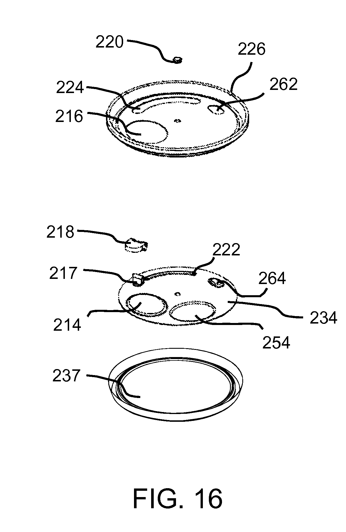
[0049] FIG. 16 is an exploded perspective view of a lid assembly, according to an embodiment of this disclosure.
[0050] FIG. 17 is a top plan view of a lid assembly in a closed state, according to an embodiment of this disclosure.
[0051] FIG. 18 is a top plan view of a lid assembly in an opened state, according to an embodiment of this disclosure.
[0052] FIG. 19 is a top plan view of a lid assembly in a partially opened state, according to an embodiment of this disclosure.
[0053] FIG. 20 is a partial perspective view of a lid assembly in a closed state, according to an embodiment of this disclosure.
[0054] FIG. 21 is a partial perspective view of a lid assembly including a tab in an unlocked, sealed configuration, according to an embodiment of this disclosure.
[0055] FIG. 22 is a partial perspective view of a lid assembly including a tab in an unlocked, unsealed configuration, according to an embodiment of this disclosure.
[0056] FIG. 23 is a partial perspective view of a lid assembly including a tab in an unlocked, opened configuration, according to an embodiment of this disclosure.
[0057] FIG. 24 is a partial cross-section view of a lid assembly including a tab in a locked, sealed configuration, according to an embodiment of this disclosure.
[0058] FIG. 25 is a partial cross-section view of a lid assembly including a tab in an unlocked, sealed configuration, according to an embodiment of this disclosure.
[0059] FIG. 26 is a partial cross-section view of a lid assembly including a tab in an unlocked, unsealed configuration, according to an embodiment of this disclosure.
DETAILED DESCRIPTION
[0060] The following disclosure is provided to describe various embodiments of a resealable lid assembly. Skilled artisans will appreciate additional embodiments and uses of the present invention that extend beyond the examples of this disclosure. Terms included by any claim are to be interpreted as defined within this disclosure. Singular forms should be read to contemplate and disclose plural alternatives. Similarly, plural forms should be read to contemplate and disclose singular alternatives. Conjunctions should be read as inclusive except where stated otherwise.
[0061] Expressions such as "at least one of A, B, and C" should be read to permit any of A, B, or C singularly or in combination with the remaining elements. Additionally, such groups may include multiple instances of one or more element in that group, which may be included with other elements of the group. All numbers, measurements, and values are given as approximations unless expressly stated otherwise.
[0062] Various aspects of the present invention will now be described in detail, without limitation. In the following disclosure, a resealable lid assembly will be discussed. Those of skill in the art will appreciate alternative labeling of the resealable lid assembly as a resealable can lid, container lid, resealable cap, cover, top, the invention, or other similar names. Similarly, those of skill in the art will appreciate alternative labeling of the method of resealably opening a lid assembly as a container resealing, selectively accessing a container, method, operation, the invention, or other similar names. Skilled readers should not view the inclusion of any alternative labels as limiting in any way.
[0063] Referring now to FIGS. 1-26, the resealable lid assembly will now be discussed in more detail. The resealable lid assembly may include a lid assembly, external lid layer 26, valve lid layer 34, pivot 20, tab 18, flow outlet components, optional vent components, tab slot components, seals, and additional components that will be discussed in greater detail below. The resealable lid assembly may operate one or more of these components interactively with other components to provide a substantially resealable lid for a container 28.
[0064] Unless otherwise specified, all references to lids and lid assemblies in this disclosure relate to lids attachable to a container 28, for example, cans. References to lid assemblies may also extend to lids that are attached to beverage cans, soda cans, beverage containers, food containers, and/or any other fluid-filled vessels that utilize a lid to retain the contents of the vessel.
[0065] Additionally, unless otherwise specified, references made to containers 28 may include vessels for liquids, foods, non-consumable fluids, and other substances. The containers 28 and/or lid assemblies may be constructed using a variety of materials, including metals, plastics, synthetics, rubbers, and/or other materials that would be apparent to those of skill in the art.
[0066] While containers, including metal cans, may be used for many purposes, one of the more widely used functions is for fluid packaging, more specifically, fluid packaging of carbonated beverages. Throughout this document, "lid" or "lid assembly" may be used interchangeably to describe the portion of the can assembly that may reside on the top portion of the container and may substantially seal the liquid in the container. Furthermore, a soda can, beverage can, beverage container, or fluid-filled vessel may be referred to as "container," "can," or "can assembly." References to lids and cans throughout this document are general statements and are exemplary or illustrative of typical use for the purpose of explaining this design. In some cases, "can" may refer to the entire assembly of can and lid (or lid assembly) and this will be discernable based upon the context. Every effort will be made to be clear and concise throughout the specification for this patent application. Furthermore, the lid assembly may be interchangeably referred to as "device" or "apparatus" throughout this document. It is not the intent of this application to make any additional limit of the disclosed embodiments as requiring the fluid-holding portion of the can (i.e. deep drawn portion of can). More specifically, it is the intent of this application to focus on the means by which fluid is retained by and dispensed from a can by introducing a novel and unique lid assembly design, which may include an integrated valve in some embodiments.
[0067] The lid assembly may generally include two components: an external lid layer 26 and a valve lid layer 34 that are rotatable about a pivot 20. These two components, which may also be included with several other components and features, may provide the overall mechanical functionality for the lid assembly. The lid assembly may be adaptable to existing containers 28 or interchangeable with existing container lids, for example beverage can lids. When used, the lid assembly may provide an ability to close a container 28, such as a beverage can, even after it has been opened.
[0068] The lid assembly may be made independently of the fluid-holding portion of the container 28. An example of a container may include, without limitation, metal components may be shaped and constructed via conventional metal stamping or forming. In one example of attaching a lid assembly to a container, metals that are typically used for such products may be slightly elastic and provide the ability for the device to deflect and deform based upon the stiffness of the material, the force applied to the part, and the geometry of the part. The lid assembly can interchangeably replace existing can lids. Optimally, the lid assembly of this invention may universally replace all existing container lids with this advantageous and more functional design.
[0069] Referring now to FIGS. 1-11, the external lid layer 26 will now be discussed in greater detail. The external lid layer 26 may be virtually any size and/or shape compatible with a container 28 on which it may be attached. In one embodiment, the external lid layer 26 may be a substantially round disk that is stamped and/or formed in a flat or convex shape with the convex side upward facing orientation. The external lid layer 26 may include cutouts, for example, a flow outlet hole 16, an optional vent hole 262, a finger tab slot hole 24, and a pivot hole 50. A pusher feature upset 48 may be included near an end, for example the counterclockwise-most end, of the finger tab slot hole 24 to allow for concealment of pusher features 144 includable on the finger tab 18.
[0070] Once the external lid layer 26 has been formed and/or blanked, a secondary process may be performed to apply optional sealant around the openings in the external lid layer 26. The sealant may be applied locally to the bottom-facing flat or concave surface around the outlines of each of the openings or to the entire bottom-facing flat or concave surface of the external lid layer 26.
[0071] In one embodiment, the external lid layer 26 may be a substantially circular piece of material that includes the flow outlet hole 16 and finger tab slot hole 24, through which at least part of a tab 18 may be passed. The external lid layer 26 may optionally include a vent hole, which may provide a pathway for air or another fluid to pass between the interior and exterior of the container 28 on which the lid assembly is installed.
[0072] Referring now to FIGS. 2-6 and 10-11, the valve lid layer 34 will now be discussed in greater detail. The lid assembly may include a valve lid layer 34 that may be rotated about a pivot 20 with respect to the external lid layer 26. The valve lid layer 34 may include a flow outlet 54, flow upset 14, tab slot upset 22, and pivot hole 52. The tab slot upset 22 may be provided as a ramp. The valve lid layer 34 may be virtually any shape that provides the flow outlet 54 and flow upset 14. The tab slot upset 22 may provide the ability to partially open, fully open, partially close, and fully close a beverage can by limiting how much fluid can flow out of the can based upon the size of the adjusted flow aperture.
[0073] The valve lid layer 34 may be rotatable via the pivot 20. The valve lid layer 34 may be virtually any size and/or shape compatible with additional components of the lid assembly. The valve lid layer 34 may be configured with dimensions allowing the valve lid layer 34 to be located at least partially within a container 28 on which the lid assembly may be attached. In one embodiment, the valve lid layer 34 may be a substantially round disk that is stamped and/or formed in a flat or convex shape with the convex side upward facing orientation. The valve lid layer 34 may include cutouts, for example, a flow outlet 54 and optionally a vent. The valve lid layer 34 may additionally include upsets, for example, the flow upset 14, tab slot upset 22, and optionally a vent upset. The valve lid layer 34 upsets may facilitate engagement and mating features of the lid assembly. The pivot hole 52 may be substantially aligned with the pivot hole 50 of the external lid layer 26. A pivot 20 may be inserted through both pivot holes 50, 52. The tab 18 may be operatively attached to the valve lid layer 34, for example, via the slot tab upset 22. The valve lid layer 34 may omit additional holes for ventilation due to the ventilation permitted by the deflection of the tab slot upset 22 as it creates an air flow path through the tab slot hole 24 as the valve lid layer 34 is rotated.
[0074] Referring now to FIGS. 2-3 and 10-11, an illustrative engagement structure between the external lid layer 26 and the valve lid layer 34 will now be discussed, without limitation. The external lid layer 26 may include an outer engagement channel 12. The valve lid layer 34 may include an outer engagement rim 44 that is compatible with the outer engagement channel 12. The outer engagement channel 12 and corresponding rim 44 may facilitate alignment between the external lid layer 26 and the valve lid layer 34. The outer engagement channel 12 and corresponding rim 44 may also enhance a seal between these parts.
[0075] The lid assembly may additionally include a flow upset engagement channel 42 and corresponding flow outlet hole engagement lip 33 to enhance the seal made when the lid assembly is locked in the closed position. For example, a force that presses the valve lid layer 32 against the external lid layer 26 when the tab 18 is in a tab down position may additionally press the flow outlet hole engagement lip 33 against the flow upset engagement channel 44, substantially closing the flow aperture and sealing the flow outlet components.
[0076] In one embodiment of this disclosure, the outer engagement channel 12 may be circumferentially located about the external lid layer 26 with a radius that is smaller than a substantially circumferential attachment interface between the lid assembly and container 28. The outer engagement rim 44 may substantially fit within the outer engagement channel 12 when the lid assembly is in the closed configuration. Additionally, the outer engagement rim 44 may be at least partially displaced from the outer engagement channel 12 as the lid assembly is unsealed, which may occur as a step to move the lid assembly into the opened configuration.
[0077] Referring now to FIGS. 1-11, the pivot 20 will now be discussed in greater detail. The pivot 20 may be at least partially inserted with a pivot hole 50 on the external lid layer 26 and a pivot hole 52 on the valve lid layer 34. The pivot 20 may be substantially fixed to pivot hole 50 of the external lid layer 26, allowing the valve lid layer 34 to rotate at least partially via the pivot 20 passing through the pivot hole 52 of the valve lid layer 34. Alternatively, the pivot 20 may be movable within the pivot hole 50 of the external lid layer 26 and substantially fixed to the pivot hole 52 of the valve lid layer 34. In yet another configuration, the pivot 20 may be substantially movably located within the pivot holes 50, 52 of the external lid layer 26 and the valve lid layer 34, respectively, allowing valve lid layer 34 may be movable via the pivot 20 passing through its pivot hole 52. The pivot 20 may additionally pass through the tab 18.
[0078] The pivot 20 may provide a mechanical attachment and rotational alignment between the external lid layer 26 and the valve lid layer 34. The pivot 20 may include a rivet or other structure. Multiple pivots may optionally be provided, affecting movement of various features of the external lid layer 26 and/or the valve lid layer 34. A pivot seal may be applied to at least part of the bottom surface of the external lid layer 26 and/or a surface of the valve lid layer 34 to provide a hermetic seal between the pivot 20 and layers of the lid assembly.
[0079] Referring now to FIGS. 1-13, the tab 18 will now be discussed in greater detail. The tab 18 may be virtually any length of material extending from the valve lid layer 34 through at least part of the external lid layer 26. The valve lid layer 34 may be at least partially rotatable via the pivot 20 via the tab 18. The tab 18 may be provided as a foldable finger tab that permits stackability of containers 28 including the lid assembly. Inclusion of a foldable tab advantageously reduces the likelihood of the tab 18 being accidentally contacted and the substantially hermetic seal of the lid assembly being breached by subsequent containers 28 in a stack, for example, multiple cans in other packaging configurations such as boxes.
[0080] The tab 18 may utilize features that simultaneously push up on the bottom surface of the external lid layer 26 and then down on the top surface of the valve lid layer 34 to create a separation force between the external lid layer 26 and the valve lid layer 34. This separation force may at least partially breach or break the seal so that the valve lid layer 34 may rotate freely with respect to the external lid layer 26. The tab slot upset 22 may be configured as a ramp, which may further apply a separation force between the external lid layer 26 and the valve lid layer 34 as the tab 18 is moved about the tab slot hole 24, for example, to the opened position.
[0081] In one embodiment, the tab 18 may be configured as a piece of formed sheet metal with similar construction to a conventional soda can tab. A central end of the tab 18 may be attached near the center of the lid assembly, for example, at or near the pivot 20. The pivot 20 may pass through a pivot hole 152 of the tab 18. A distal end of the tab 18 may extend outwardly from the center of the lid assembly, for example, to the outer circumference or edge of the lid assembly. The distal end of the tab 18 may be attached to the valve lid layer 34 at its far end via pivots, welds, or other similar mechanical attachment structures as the tab central end. The tab may additionally include a pusher dimple 145 at the end of a pusher tooth 146 at the distal end of the tab 18. A weight reduction feature 142 may be included to decrease the quantity of material required to construct the tab 18, and thus the weight of the tab 18.
[0082] A bendable portion of the tab 18 may be connected to the attachment locations about a bend line 150. In its initial state, the tab 18 may substantially prevent the tab 18 from being displaced in a downward direction and accidentally breaking the hermetic seal. When the user is ready to "open" the container 28, the user may merely engage the fingertip grip feature 148 to flip, or bend the tab "up". As an example, the user may grip the tab 18 between index finger and thumb and rotate the tab 18 about the main rotation axis to rotate and thus open/close the lid once the seal is broken. Pusher features 144 may be located on the finger tab 18 at the tab distal end to separate the valve lid layer 34 from the lid seals as the tab is bent upwards. As the separation occurs, the valve lid layer 34 may be deflected in a downward direction, thus continuing to add to the separation between external lid layer 26 and the valve lid layer 34.
[0083] Referring now to FIGS. 1-11, the flow outlet 54, flow outlet hole 16, flow upset 14, and flow aperture will now be discussed in greater detail. As discussed above, the external lid layer 26 may include a flow outlet hole 16. Additionally, the valve lid layer 34 may include a flow outlet 54 and a flow upset 14. In a closed configuration, the flow upset 14 may be located substantially within the flow outlet hole 16, substantially closing the flow aperture and preventing the egress of liquid through the lid assembly. In an opened configuration, the flow upset 14 may be located away from the flow outlet hole 16, substantially opening the flow aperture and permitting egress of liquid through the lid assembly. The flow outlet 54 may substantially align with the flow outlet hole 16 to increase the flow aperture and allow the egress of liquid from the container 28. The lid assembly may be configured at least partially between the opened configuration and the closed configuration, providing a flow aperture that is partially opened. The flow upset 14 of the valve lid layer 34 may provide for mechanical engagement, which may include a between the flow upset 14 of the valve lid layer 34 and flow outlet hole 16 of the external lid layer 26 to enhance the seal when closed. The mechanical engagement may be enhanced by the flow upset engagement channel 42 and the flow outlet engagement lip 33.
[0084] Referring now to FIGS. 1 and 3-9, the tab slot hole 24 and tab slot upset 22 will now be discussed in greater detail. As discussed above, the external lid layer 26 may include a tab slot hole 24 and the valve lid layer 34 may include a tab slot upset 22. The tab slot upset 22 in the valve lid layer 34 may provide for deflection of the valve lid layer 34. The tab 18 may be operatively attached to at least part of the tab slot upset 22. The tab 18 may be passed at least partially through the tab slot hole 24. The tab 18 may be moved within a length provided by the tab slot hole 24. Movement of the tab 18 within the tab slot hole 24 may adjust the orientation of the valve lid layer 34. Thus, movement of the tab 18 may adjust the positions of the flow outlet 54 and flow upset 14 with respect to the flow outlet hole 16, further adjusting the flow aperture. Moving the tab 18 about the tab slot hole 24 may also adjust the mechanical separation between the external lid layer 26 and valve lid layer 34 as the valve lid layer 34 is rotated to a partially or fully opened state. The tab slot upset 22 may include a pusher dimple 45, which may facilitate loosening the seal when the lid assembly is altered between the closed configuration and the opened configuration.
[0085] Referring now to at least FIG. 2, the flow seal 32 will now be discussed in greater detail. The flow seal 32 may substantially prevent egress of fluid through the flow outlet hole 16 while the lid assembly is in the closed configuration. The flow seal 32 may be mechanically attached to the bottom surface of the external lid layer 26 and may provide a hermetic seal between the external lid layer 26 flow outlet hole 16 and valve lid layer 34 flow upset 14. A slot seal may also be included that may be mechanically attached to the bottom surface of the external lid layer 26 and may provide a hermetic seal between the external lid layer 26 tab slot hole 24 and/or optional vent hole and valve lid layer 34 tab slot upset 22.
[0086] In one embodiment, while the flow seal 32 is still in an un-cured or partially cured state, the external lid layer 26, valve lid layer 34, and tab may be aligned to one another, assembled, and then pivoted together with the external lid layer 26 on top and the valve lid layer 34 on the bottom. The feature alignment may ensure that the flow dimple 35 of the valve lid layer 34 may be aligned with the respective receiving cutout in the external lid layer 26. An optional vent dimple in the valve lid layer 34 may be aligned with the respective optional receiving vent cutout in the external lid layer 26. The tab 18 may be inserted into the tab slot hole 24. The pivot holes 50, 52 on all parts may be axially aligned. The pivots 20 may then be inserted into their respectively aligned pivot holes 50, 52 and may be deformed to as required. The pivot 20 may provide sufficient force to the flow seal 32 and other seals between the external lid layer 26 and valve lid layer 34 so that the sealant may become slightly compressed and form a high quality substantially hermetic seal around each of the openings.
[0087] Referring now to at least FIGS. 2-3, and 10, the sealant 37 will now be discussed in greater detail. The sealant may be applied to at least part of the lid assembly to facilitate creating a seal while in the closed configuration.
[0088] Further sealing and alignment between the external lid layer 26, valve lid layer 34, other parts of the lid assembly, and the container 28 may be accomplished by the alignment channel and alignment lip on the external lid layer 26 and valve lid layer 34, respectively. These features may enhance the alignment between the parts and may advantageously provide for another sealant location.
[0089] In operation, the lid assembly may be used to reversibly open and substantially reseal a container 28. The operation may include configuring the tab 18 in a tab up position, such as illustrated in FIGS. 1-2, 4, 7, 10, and 12, to unlock the lid assembly. By configuring the tab in the tab up configuration, such as illustrated in FIGS. 5-6, 8-9, 11, and 13, the valve lid layer 34 may be at least partially separated from the external lid layer 26 to enable rotation of the valve lid layer 34 via the pivot 20. The tab 18 may be operatively connected to the valve lid layer 34. The operation may additionally include moving the tab 18 within a length of a tab slot hole 24 of the external lid layer 26. By moving the tab 18, the valve lid layer 34 may be rotated via the pivot 20. Rotation of the valve lid layer 34 may alter the lid assembly between a closed configuration, such as illustrated in FIGS. 1-2, 4, 7-8, and 10-11, and an opened configuration, such as illustrated in FIGS. 5 and 9.
[0090] In one example, the lid assembly, including the valve lid layer 34, may start in the closed configuration, as illustrated in FIGS. 4 and 7. In this closed configuration of the lid assembly, the flow upset 14 may be oriented below the flow outlet hole 16. With the tab 18 in the down position, the flow aperture may be substantially closed and sealed. The tab 18 may then be moved into the tab up position, moving the valve lid layer 34 away from the external lid layer 26, as illustrated in FIG. 8, and thus moving the flow upset 14 away from its resting place in the flow outlet hole 16.
[0091] The tab 18 may then be moved about the length of the tab slot hole 24 to rotate the valve lid layer 34 via the pivot 20. As the valve lid layer 34 is rotated, the flow upset 14 may be moved away from the flow outlet hole 16 and a flow outlet 54 may be moved closer to the flow outlet hole 16 to vary a flow aperture. When the flow aperture is sufficiently opened, as illustrated in FIGS. 5 and 9, a fluid may egress from the flow outlet hole 16 through the flow aperture.
[0092] When the valve lid layer 34 is in the desired orientation with respect to the external lid layer 26, the tab 18 may be moved into the tab down position. With the tab 18 in the tab down position, the valve lid layer 34 may be substantially locked into place with respect to the external lid layer 26. To reseal the container 28, the above illustrative operation may be performed in reverse to again locate the flow upset 14 in the flow outlet hole 16 in a substantially locked configuration.
[0093] The valve lid layer 34 may be partially rotated between the closed configuration and the opened configuration, as illustrated in FIG. 6. In a partially opened configuration, the flow outlet 54 of the valve lid layer 34 may be located less than completely under the flow outlet hole 16 of the external lid layer 26, providing a partially opened flow aperture. Skilled artisans will appreciate various configurations in which the lid assembly may be opened between fully closed and fully opened after having the benefit of this disclosure.
[0094] In one embodiment, filling the container 28 with a soda or other beverage may increase the pressure inside the container 28, for example due to carbonation. The increased pressure inside the container 28 may apply a uniform pressure to the valve lid layer 34 essentially "helping" the valve lid layer 34 to remain closed.
[0095] Additionally, upon the first use of the container 28, the user may bend the finger tab 18 up or otherwise manipulate the tab 18 into the tab up position. This action may cause pusher features 145, 146 on the tab to engage the respective pusher features 35 on the external lid layer 26, thus causing the tab pusher features 145, 146 to push up on the bottom surface of the external lid layer 26 and down on the top surface of the valve lid layer 34. This force and respective deflection may cause the valve lid layer 34 to substantially peel away from a sealant and initially relieve any pressure in the can.
[0096] Once the valve lid layer 34 is peeled away from the sealant, the user may apply a lateral force to the tab 18 to rotate the tab 18 in a direction, for example a clockwise direction. The tab 18 may be rotated until it contacts the far end of the tab slot hole 24, substantially aligning the flow outlet 54 of the valve lid layer 34 with the flow outlet hole 16 in the external lid layer 26. The lid assembly can be adjusted in-between fully opened and fully closed as well by merely rotating the tab in various directions, for example a clockwise or counterclockwise direction, thus changing the effective size of the flow aperture or orifice. After the initial opening, the user can open and close the lid several times.
[0097] Referring now to FIGS. 14-26, along with FIGS. 1-13 described above, an additional embodiment of the disclosure will be described below. This embodiment may similarly include a lid assembly with an external lid layer 226, valve lid layer 234, tab 218, sealant, seals and other features. This embodiment of the lid assembly may provide for the ability to close a container even after it has been opened. The lid assembly may include a pivot 220 that provides a mechanical attachment and rotational alignment between the external lid layer 226 and valve lid layer 234. The lid assembly of this embodiment may additionally include a tab 218 that provides for stackability of containers.
[0098] Similar to the discussion above, this embodiment may include a flow upset 214 in the valve lid layer 234 that provides for mechanical engagement between the valve lid layer 234 and flow outlet hole 216 of the external lid layer 226 to enhance the seal when closed. This embodiment may additionally include seals, including a flow seal, that may be mechanically attached to the bottom surface of the external lid layer 226 and provide a substantially hermetic seal between the external lid layer 226 flow outlet hole 216 and valve lid layer 234 flow upset 214. A flow aperture may be adjusted by changing orientation of the flow upset 214 and a flow outlet 254 with respect to the flow outlet hole 216. This embodiment may additionally include a sealant 237, which may be applied to at least part of the lid assembly to facilitate creating a seal while in the closed configuration.
[0099] Referring additionally to FIGS. 14-26, the tab 218 will now be discussed. The tab 218 may be operatively connected to a tab base 217. The tab base 217 may be operatively connected to valve lid layer 234, for example, via a tab slot upset 222 of the valve lid layer 234. The tab base 217 may be a piece of material, for example sheet metal, which may be attached to the valve lid layer 234, for example, via spot welds or rivets. A rotatable tab 218 may be pivotally connected to the tab base 217. In the "down" position, the tab 218 may prevent the tab 218 from being displaced in a downward direction and accidentally breaking the hermetic seal. When the user is ready to "open" the container, the user may flip the tab "up" and then vertically press in a downward direction on the tab 218 to initially break the hermetic seal. The user may then laterally press on the tab 218 and/or tab base 217 to open/close the lid assembly once the seal is broken. The vertical deflection feature of the tab 218 may prevent the lid from becoming over-deflected and taking a permanent set.
[0100] Referring now to FIGS. 14 and 16-23, the tab slot hole 224 and tab slot upset 222 will now be discussed. The external lid layer 226 may include a tab slot hole 224, which may be similar in construction to the tab slot hole 24 discussed above, to facilitate travel of a tab 218 throughout the length of the tab slot hole 224. The valve lid layer 234 may include a tab slot upset 222, which may be similar in construction to the tab slot upset 22 discussed above. The tab slot upset 222 of this embodiment may be substantially fitted into the tab slot hole 224 when the lid assembly is in the closed configuration, substantially sealing the tab slot hole 224. When the valve lid layer 234 is rotated to place the lid assembly in the opened configuration, at least part of the tab slot upset 222 may be rotated under a vent hole 262.
[0101] Referring to FIGS. 14 and 16-23, the vent hole 262 and vent upset 264 will now be discussed. The vent hole 262 and vent upset 264 are provided in this example to illustrate a possible configuration that includes discrete venting structures. Skilled artisans will appreciate additional configurations of this and other embodiments that exclude the vent hole 262, vent upset 264, or both. Illustration of the vent hole 262 and vent upset 264 in FIGS. 14 and 16-23 are not intended to limit this disclosure to embodiments including discrete venting structures or other specific venting structures in any way.
[0102] The external lid layer 226 may include a vent hole 262, which may allow air or other fluids to pass when the lid assembly is in the opened configuration. The valve lid layer 234 may include a vent upset 264, which may be substantially fitted into the vent hole 262 when the lid assembly is in the closed configuration, substantially sealing the vent hole 264. When the valve lid layer 234 is rotated to place the lid assembly in the opened configuration, at least part of the vent upset 262 may be rotated away from its original location under the vent hole 264 to vary a vent aperture. At least part of the tab slot upset 222 may be rotated under the vent hole 262, which may provide a gap though which air or other fluids may be vended when the lid assembly is in the opened configuration.
[0103] While various aspects of the invention have been described in the above disclosure, the description of this disclosure is intended to illustrate and not limit the scope of the invention. The invention is defined by the scope of the appended claims and not the illustrations and examples provided in the above disclosure. Skilled artisans will appreciate additional aspects of the invention, which may be realized in alternative embodiments, after having the benefit of the above disclosure. Other aspects, advantages, embodiments, and modifications are within the scope of the following claims.
* * * * *
D00000
D00001
D00002
D00003
D00004
D00005
D00006
D00007
D00008
D00009
D00010
D00011
D00012
D00013

D00014

D00015

D00016

D00017

XML
uspto.report is an independent third-party trademark research tool that is not affiliated, endorsed, or sponsored by the United States Patent and Trademark Office (USPTO) or any other governmental organization. The information provided by uspto.report is based on publicly available data at the time of writing and is intended for informational purposes only.
While we strive to provide accurate and up-to-date information, we do not guarantee the accuracy, completeness, reliability, or suitability of the information displayed on this site. The use of this site is at your own risk. Any reliance you place on such information is therefore strictly at your own risk.
All official trademark data, including owner information, should be verified by visiting the official USPTO website at www.uspto.gov. This site is not intended to replace professional legal advice and should not be used as a substitute for consulting with a legal professional who is knowledgeable about trademark law.