Plastic Containers Having Base Configurations With Up-stand Walls Having A Plurality Of Rings, And Systems, Methods, And Base Molds Thereof
Wurster; Michael P. ; et al.
U.S. patent application number 14/846432 was filed with the patent office on 2015-12-31 for plastic containers having base configurations with up-stand walls having a plurality of rings, and systems, methods, and base molds thereof. This patent application is currently assigned to GRAHAM PACKAGING COMPANY, L.P.. The applicant listed for this patent is GRAHAM PACKAGING COMPANY, L.P.. Invention is credited to Scott E. Bysick, Michael P. Wurster.
| Application Number | 20150375883 14/846432 |
| Document ID | / |
| Family ID | 47711892 |
| Filed Date | 2015-12-31 |


View All Diagrams
| United States Patent Application | 20150375883 |
| Kind Code | A1 |
| Wurster; Michael P. ; et al. | December 31, 2015 |
PLASTIC CONTAINERS HAVING BASE CONFIGURATIONS WITH UP-STAND WALLS HAVING A PLURALITY OF RINGS, AND SYSTEMS, METHODS, AND BASE MOLDS THEREOF
Abstract
Plastic containers, base configurations for plastic containers, and systems, methods, and base molds thereof. In particular, the disclosed subject matter involves container base configurations having particular up-stand geometries that can assist or facilitate elevated temperature processing and/or cooling processing of plastic containers.
| Inventors: | Wurster; Michael P.; (York, PA) ; Bysick; Scott E.; (Elizabethtown, PA) | ||||||||||
| Applicant: |
|
||||||||||
|---|---|---|---|---|---|---|---|---|---|---|---|
| Assignee: | GRAHAM PACKAGING COMPANY,
L.P. YORK PA |
||||||||||
| Family ID: | 47711892 | ||||||||||
| Appl. No.: | 14/846432 | ||||||||||
| Filed: | September 4, 2015 |
Related U.S. Patent Documents
| Application Number | Filing Date | Patent Number | ||
|---|---|---|---|---|
| 13210350 | Aug 15, 2011 | 9150320 | ||
| 14846432 | ||||
| Current U.S. Class: | 53/440 |
| Current CPC Class: | B65D 1/40 20130101; B65B 63/08 20130101; B65D 1/0276 20130101; B67C 2003/226 20130101; B65B 3/04 20130101; B65D 79/005 20130101; B65B 61/24 20130101; B65B 7/2842 20130101 |
| International Class: | B65B 63/08 20060101 B65B063/08; B65B 7/28 20060101 B65B007/28; B65D 1/40 20060101 B65D001/40; B65B 3/04 20060101 B65B003/04; B65D 1/02 20060101 B65D001/02; B65D 79/00 20060101 B65D079/00 |
Claims
1. A method comprising: providing a blow-molded plastic container, the plastic container including a sidewall configured to support a film label, a finish projecting from an upper end of the sidewall and operative to cooperatively receive a closure to sealingly enclose the plastic container, and a base extending from the sidewall to form a bottom enclosed end of the plastic container, wherein the bottom end comprises: an annular bearing portion defining a standing surface for the container, the base being smooth and without surface features from said bearing portion to said lower label stop, a cylindrical wall including a first concave ring, a second concave ring, and a third concave ring, the cylindrical wall circumscribed by said bearing portion and extending continuously upward from said bearing portion toward said wide-mouth finish generally in a radially inward direction, the first concave ring being continuous throughout a first circumference of the cylindrical wall and defined by a first diameter and a first cross-sectional radius, the second concave ring extending directly from the first concave ring continuous throughout a second circumference of the cylindrical wall and defined by a second diameter and a second cross-sectional radius, and the third concave ring extending directly from the second concave ring continuous throughout a third circumference of the cylindrical wall and defined by a third diameter and a third cross-sectional radius, the first diameter being greater than the second and third diameters, and the second diameter being greater than the third diameter, and an inner wall circumscribed by said cylindrical wall with an annular shoulder therebetween, hot-filling the plastic container via the finish with a product; sealing the hot-filled plastic container with the closure; and cooling the hot-filled and sealed plastic container; wherein an internal pressure characteristic after hot-filling and sealing the plastic container is compensated by the inner wall with substantially no movement of the cylindrical wall.
2. The method of claim 1, wherein each of the first, second, and third concave rings has a different circumference.
3. The method of claim 1, further comprising: blow molding the plastic container using a mold comprised of a base mold that forms the cylindrical wall and the inner wall; conveying the plastic container with its standing ring resting on a flat surface while the internal pressure is compensated by the inner wall; and performing at least one of pasteurization and retort processing on the filled and sealed container after said filling and sealing.
4. The method of claim 1, wherein the plastic container is a wide-mouth jar.
5. The method of claim 1, wherein a temperature of the hot-filled product upon filling is from 200.degree. F. to 205.degree. F.
6. The method of claim 5, wherein the internal pressure is compensated by movement of the inner wall outward in response to an overpressure created in the hot-filled and sealed container.
7. The method of claim 5, wherein said inner wall and said cylindrical wall are cooperatively operative so as to accommodate pressure variation within the container after the container has been hot-filled with a product at a temperature from 200.degree. F. to 205.degree. F. and sealed with the closure, said inner wall being operative to flex in response to the pressure variation within the container after the container has been hot-filled and sealed with the closure, whereas said cylindrical wall is operative to withstand movement as said inner wall flexes in response to the pressure variation within the container after the container has been hot-filled and sealed with the closure.
8. The method of claim 1, wherein the plastic container is a wide-mouth jar, wherein a temperature of the hot-filled product upon filling is from 200.degree. F. to 205.degree. F., wherein the portion of the base from the sidewall to the standing ring is smooth and without surface features, wherein the first concave ring has a greater circumference than the third concave ring, and wherein the internal pressure is compensated by movement of the inner wall outward in response to an overpressure created in the hot-filled and sealed jar.
9. The method of claim 1, wherein the portion of the base from the sidewall to the standing ring is smooth and without surface features,
10. The method of claim 1, wherein the first concave ring has a greater circumference than the third concave ring.
11. The method of claim 10, wherein the second concave ring has a circumference between the respective circumferences of the third and first concave rings.
12. The method of claim 1, wherein the cylindrical wall further includes a fourth concave ring extending directly from the third concave ring and defined by a fourth diameter and having a fourth cross-sectional radius, the first, second, and third diameters being greater than the fourth diameter.
13. The method of claim 1, wherein the plastic container is a wide-mouth jar, wherein a temperature of the hot-filled product upon filling is from 185.degree. F. to 205.degree. F.
14. The method of claim 13, wherein the internal pressure is compensated by movement of the inner wall inward in response to an vacuum created by said cooling, said movement inward reducing the vacuum.
15. The method of claim 13, wherein said inner wall and said cylindrical wall are cooperatively operative so as to accommodate pressure variation within the container after the container has been hot-filled with a product at a temperature from 185.degree. F. to 205.degree. F. and sealed with the closure, said inner wall being operative to flex in response to the pressure variation within the container after the container has been hot-filled and sealed with the closure, whereas said cylindrical wall is operative to withstand movement as said inner wall flexes in response to the pressure variation within the container after the container has been hot-filled and sealed with the closure.
16. The method of claim 15, wherein the pressure variation is headspace pressure associated with the hot-filling with the product at the temperature from 185.degree. F. to 205.degree. F. and sealing the container, said inner wall being configured and operative to flex downward in response to the headspace pressure, and said sidewall withstands movement in response to the pressure variation.
17. The method of claim 16, wherein said inner wall is constructed so as to be at or above the bearing surface at all times when the inner wall flexes in response to the headspace pressure.
18. The method of claim 15, wherein the pressure variation is an internal vacuum associated with cooling of the hot-filled and sealed container, said inner wall being configured and operative to flex upward and inward in response to the vacuum, and said sidewall withstands movement in response to the vacuum.
19. The method according to claim 18, wherein the upward and inward flexing of said inner wall at least partially reduces the vacuum in the container.
20. The method of claim 1, wherein the plastic container is a wide-mouth jar, wherein a temperature of the hot-filled product upon filling is from 185.degree. F. to 205.degree. F., wherein the portion of the base from the sidewall to the standing ring is smooth and without surface features, wherein the first concave ring has a greater circumference than the third concave ring, and wherein the internal pressure is compensated by movement of the inner wall inward in response to an vacuum created by said cooling, said movement inward reducing the vacuum.
Description
CROSS-REFERENCE TO RELATED APPLICATIONS
[0001] This application is a divisional of U.S. patent application Ser. No. 13/210,350 filed Aug. 15, 2011, which is incorporated by reference herein in its entirety.
FIELD
[0002] The disclosed subject matter relates to base configurations for plastic containers, and systems, methods, and base molds thereof. In particular, the disclosed subject matter involves base configurations having particular up-stand geometries that can assist or facilitate elevated temperature processing and/or cooling processing of plastic containers.
SUMMARY
[0003] The Summary describes and identifies features of some embodiments. It is presented as a convenient summary of some embodiments, but not all. Further the Summary does not necessarily identify critical or essential features of the embodiments, inventions, or claims.
[0004] According to embodiments, a plastic container comprises: a sidewall configured to receive a label; a finish projecting from an upper end of said sidewall, said finish operative to receive a closure; and a base below said sidewall. The base has a bottom end that includes: a bearing portion defining a standing surface for plastic container; an up-stand geometry wall of a stacked configuration extending upward from said bearing portion; and an inner wall circumscribed by said up-stand geometry wall in end view of the plastic container, said inner wall and said up-stand geometry wall being cooperatively operative so as to accommodate pressure variation within the container after the container has been filled with a product and sealed with the closure, said inner wall being operative to flex in response to the pressure variation within the container after the container has been hot-filled and sealed with the closure, whereas said up-stand geometry wall is operative to withstand movement as said inner wall flexes in response to the pressure variation within the container after the container has been hot-filled and sealed with the closure.
[0005] Also included among embodiments described herein is a method comprising: providing a blow-molded plastic container, the plastic container including a sidewall configured to support a film label, a finish projecting from an upper end of the sidewall and operative to cooperatively receive a closure to sealingly enclose the plastic container, and a base extending from the sidewall to form a bottom enclosed end of the plastic container, wherein the bottom end has a standing ring upon which the container may rest, a rigid wall comprised of a plurality of stacked rings extending upward from the standing ring, and a movable wall extending inward from the rigid wall toward a central longitudinal axis of the container. The method also comprises hot-filling the plastic container via the finish with a product; sealing the hot-filled plastic container with the closure; cooling the hot-filled and sealed plastic container; and compensating for an internal pressure characteristic after hot-filling and sealing the plastic container, said compensating including substantially no movement of the rigid wall.
[0006] Embodiments also include a hot-fillable, blow-molded plastic wide-mouth jar configured to be filled with a viscous food product at a temperature from 185.degree. F. to 205.degree. F., which comprises: a cylindrical sidewall configured to support a wrap-around label; a wide-mouth threaded finish projecting from an upper end of said sidewall via a shoulder, said threaded finish operative to receive a closure, and said shoulder defining an upper label stop above said sidewall; and a base defining a lower label stop below said sidewall. The base has a bottom end that includes: a bearing portion defining a standing surface for the jar, the base being smooth and without surface features from said bearing portion to said lower label stop; an up-stand geometry wall of a stacked three-ring configuration circumscribed by said bearing portion and extending generally upward and radially inward from said bearing portion, a first ring of the stack being the bottom ring of the stack and having a first diameter, a second ring of the stack being the middle ring of the stack and having a second diameter and a third ring of the stack being the top ring and having a third diameter, the first diameter being greater than the second and third diameters, and the second diameter being greater than the third diameter. The bottom end of the base also includes an inner wall circumscribed by said up-stand geometry wall, said inner wall and said up-stand geometry wall are cooperatively operative so as to accommodate pressure variation within the jar after the jar has been hot-filled with the product at the temperature from 185.degree. F. to 205.degree. F. and sealed with the closure, said inner wall being operative to flex in response to the pressure variation within the jar after the jar has been hot-filled and sealed with the closure, whereas said up-stand geometry wall is operative to withstand movement as said inner wall flexes in response to the pressure variation within the jar after the jar has been hot-filled and sealed with the lid.
[0007] Embodiments also include a plastic container comprising: a sidewall configured to receive a label; a finish projecting from an upper end of said sidewall, said finish operative to receive a closure; and a base below said sidewall. The base has a bottom end that includes: a bearing portion defining a standing surface for plastic container; an up-stand geometry wall of a stacked configuration extending upward from said bearing portion; and an inner wall circumscribed by said up-stand geometry wall in end view of the plastic container, said inner wall and said up-stand geometry wall being cooperatively operative so as to accommodate pressure variation within the container after the container has been filled with a product and sealed with the closure, said inner wall being operative to flex in response to the pressure variation within the container after the container has been hot-filled and sealed with the closure, whereas said up-stand geometry wall is operative to withstand movement as said inner wall flexes in response to the pressure variation within the container after the container has been hot-filled and sealed with the closure. Optionally, the stacked configuration of the up-stand geometry wall includes a plurality of stacked rings, the rings all having a same circumference. Optionally, the stacked configuration of the up-stand geometry wall includes a plurality of stacked rings, the rings each having a different circumference.
[0008] In embodiments, a base mold to form a bottom end portion of a base of a plastic wide-mouth jar, the bottom end portion of the plastic jar having a bottom bearing surface of the jar, a rigid ringed wall extending upward from the bottom bearing surface and an inner flexible wall arranged inwardly of the ringed wall, wherein the base mold comprises: a body portion; a bearing surface forming portion to form a portion of the bottom bearing surface; a ringed wall forming portion to form the rigid ringed wall; a lip portion to form a ridge of the bottom end portion; and an inner flexible wall forming portion to form the inner flexible wall. The ringed wall forming portion may be comprised of a stack of three ring protrusions to form the rigid ringed wall, respective maximum diameters of the ring protrusions decreasing in value from the bottom of the stack to the top of the stack. Optionally, the inner flexible wall forming portion can include an upwardly protruding gate portion. Optionally, the base mold further can includes a ridge forming portion between said ringed wall forming portion and said inner flexible wall forming portion to form a ridge.
BRIEF DESCRIPTION OF THE DRAWINGS
[0009] Embodiments will hereinafter be described in detail below with reference to the accompanying drawings, wherein like reference numerals represent like elements. The accompanying drawings have not necessarily been drawn to scale. Any values dimensions illustrated in the accompanying graphs and figures are for illustration purposes only and may not represent actual or preferred values or dimensions. Where applicable, some features may not be illustrated to assist in the description of underlying features.
[0010] FIG. 1 is a side view of a plastic container according to embodiments of the disclosed subject matter.
[0011] FIG. 2 is a side view of another plastic container according to embodiments of the disclosed subject matter.
[0012] FIG. 3A is a cross section view of a base portion of a container according to embodiments of the disclosed subject matter.
[0013] FIG. 3B is a magnified view of the circled portion of the base portion of FIG. 3A.
[0014] FIG. 3C is a bottom end view of the base portion of FIG. 3A.
[0015] FIG. 4A is a cross section view of a base portion of a container according to embodiments of the disclosed subject matter.
[0016] FIG. 4B is cross section view of the base portion shown in FIG. 4A with a base mold according to embodiments of the disclosed subject matter.
[0017] FIG. 4C is a bottom perspective view of the base portion of FIG. 4A.
[0018] FIG. 5A is a base mold according to embodiments of the disclosed subject matter.
[0019] FIG. 58 is another base mold according to embodiments of the disclosed subject matter.
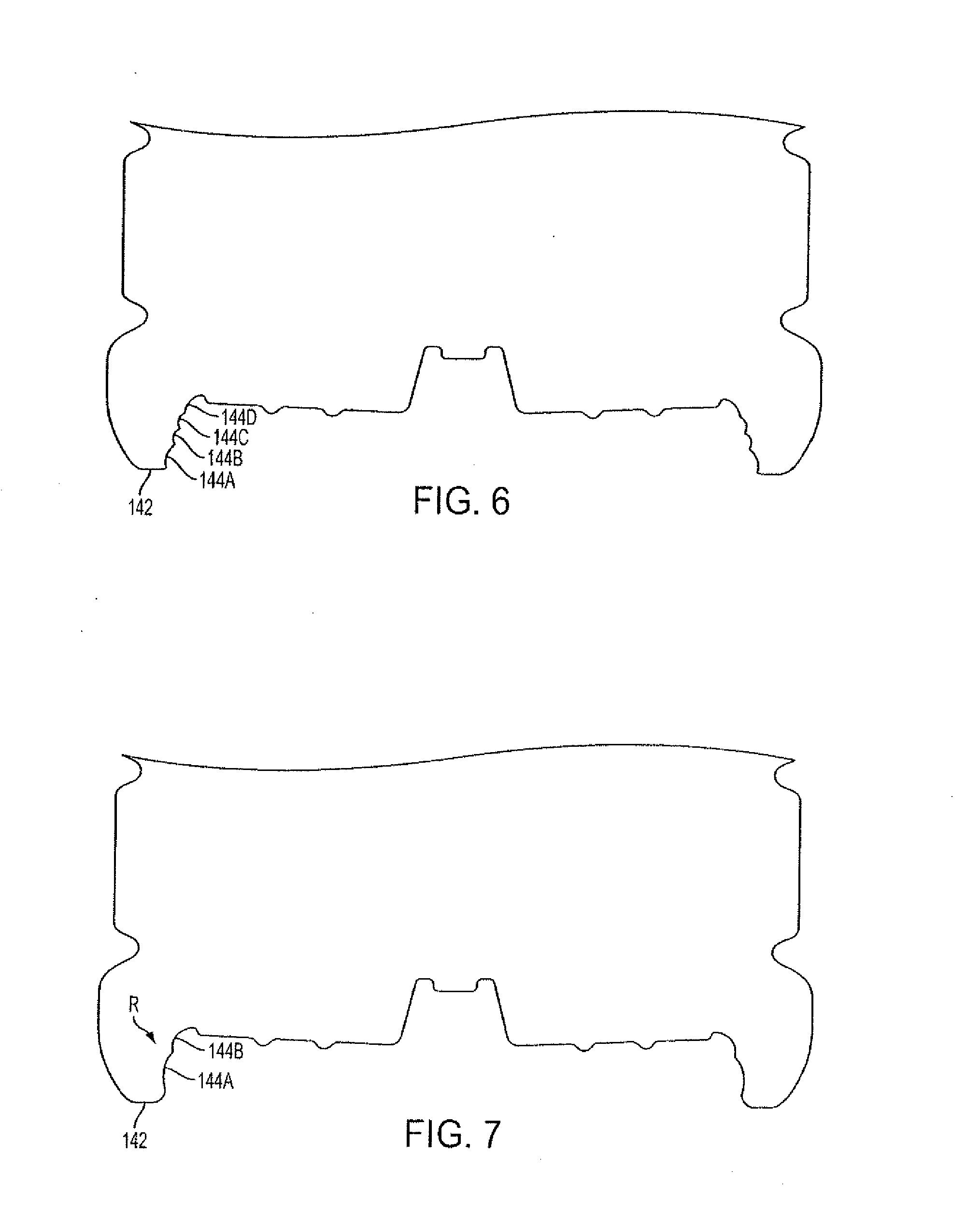
[0020] FIG. 6 shows a cross section view of an alternative embodiment of a base portion of a container according to the disclosed subject matter.
[0021] FIG. 7 shows a cross section view of another alternative embodiment of a base portion of a container according to the disclosed subject matter.
[0022] FIGS. 8A-8E illustrate alternative base mold embodiments according to the disclosed subject matter.
[0023] FIG. 9A is a cross section view of a base portion of a plastic container according to embodiments of the disclosed subject matter, similar to the base portion shown in FIG. 4A but without a ridge portion.
[0024] FIG. 9B is a cross section view of a base portion of a plastic container without a ridge portion according to embodiments of the disclosed subject matter.
[0025] FIG. 10 is a flow chart for a method according to embodiments of the disclosed subject matter.
DETAILED DESCRIPTION
[0026] The detailed description set forth below in connection with the appended drawings is intended as a description of various embodiments of the disclosed subject matter and is not intended to represent the only embodiments in which the disclosed subject matter may be practiced. The detailed description includes specific details for the purpose of providing a thorough understanding of the disclosed subject matter. However, it will be apparent to those skilled in the art that the disclosed subject matter may be practiced without these specific details. In some instances, well-known structures and components may be shown in block diagram form in order to avoid obscuring the concepts of the disclosed subject matter.
[0027] The disclosed subject matter relates to base configurations for plastic containers, and systems, methods, and base molds thereof. In particular, the disclosed subject matter involves base configurations having particular up-stand geometries that assist or facilitate elevated temperature processing, such as hot-filling, pasteurization, and/or retort processing. Optionally, plastic containers according to embodiments of the disclosed subject matter also may be configured and operative to accommodate internal forces caused by post elevated temperature processing, such as temperature-induced forces from varying temperatures in transit to or in storage at a distributor (e.g., wholesale or retail vendor), for example, prolonged effects of the weight of the product stored therein over time, etc., and/or cooling operations (including exposure to ambient temperature) after or between elevated temperature processing.
[0028] Generally speaking, in various embodiments, plastic containers according to embodiments of the disclosed subject matter have a base portion with a bottom end having an up-stand wall of a particular geometry. The up-stand wall can resist movement in response to pressure variations or forces within the container and can facilitate movement or otherwise work in conjunction with a movable portion of the bottom end of the container base.
[0029] Thus, while an up-stand wall remains stationary or substantially stationary, a bottom end portion of the container can move in response to internal pressures within the container when hot-filled and sealed, for instance. Optionally, the bottom end portion may be constructed and operative to move downwardly and axially outward in response to internal pressures, such as headspace pressure or under the weight of the product, and also to move upwardly and axially inward in response to a different internal pressure, such as an internal vacuum created within the container due to cooling or cooling processing of the container. Alternatively, the bottom end portion may be constructed and operative to resist movement in one direction, for example, a downward and axially outward direction, in response to internal pressures (e.g., headspace pressure, product weight, etc.), but may be constructed and operative to move upward and axially inward in response to a different internal pressure, such as an internal vacuum created within the container due to cooling or cooling processing of the container.
[0030] Meanwhile, the up-stand wall may extend from the standing or support portion of the container vertically or substantially vertically, angling or sloping radially inward. The up-stand wall can be constructed and operative to remain stationary during movement of the movable bottom end portion of the container. Optionally, the up-stand wall may be constructed and operative to move or flex radially inward slightly during movement of the movable bottom end portion. Optionally, the up-stand wall may be constructed and operative to move or flex radially outward during movement of the movable bottom end portion. In the case of jars, for example, the up-stand wall can remain rigid or stationary in response to relatively higher temperatures and pressures typically involved in jar applications.
[0031] In various embodiments, the up-stand geometry can be of a stacked ring or rib configuration. Any suitable number of rings or ribs can be stacked, such as two, three, four, or five. The rings can be stacked directly vertically on top of one another, or may taper inward with each successive ring. Alternatively, only one ring may be implemented. Such use of up-stand geometry, and in particular, stacked ring configurations according to embodiments of the disclosed subject matter may provide the ability to use less material to form a jar, for instance, while providing desired container characteristics, such as the container's ability to compensate for internal pressure variations within the container after hot filling and sealing.
[0032] Plastic containers according to embodiments of the disclosed subject matter can be of any suitable configuration. For example, embodiments may include jars, such as wide-mouth jars, and base configurations thereof. Embodiments may also include single serve containers, bottles, jugs, asymmetrical containers, or the like, and base configurations thereof. Thus, embodiments of the disclosed subject matter can be filled with and contain any suitable product including a fluent, semi-fluent, or viscous food product, such as applesauce, spaghetti sauce, relishes, baby foods, brine, jelly, and the like, or a non-food product such as water, tea, juice, isotonic drinks or the like.
[0033] Plastic containers according to embodiments of the disclosed subject matter can be of any suitable size. For example, embodiments include containers with internal volumes of 24 oz., 45 oz., 48 oz., or 66 oz. Also, container sizes can include single-serving and multiple-serving size containers. Further, embodiments can also include containers with mouth diameters of 38 mm, 55 mm or higher, for instance.
[0034] Hot-fill processing can include filling a product into the container at any temperature in a range of at or about 130.degree. F. to at or about 205.degree. F. or in a range of at or about 185.degree. F. to at or about 205.degree. F. For example, a wide-mouth jar can be filled with a hot product at a temperature of at or about 205.degree. F. Optionally, the hot-fill temperature can be above 205.degree. F., such as 208.degree. F. As another example, a single-serve container, such as for an isotonic, can be filled with a hot product at a temperature of 185.degree. F. or slightly below.
[0035] Plastic containers according to embodiments of the disclosed subject matter can be capped or sealed using any suitable closure, such as a plastic or metallic threaded cap or lid, a foil seal, a lug closure, a plastic or metallic snap-fit lid or cap, etc.
[0036] Plastic containers according to embodiments of the disclosed subject matter can also optionally be subjected to through processing, such as pasteurization and/or retort processing.
[0037] Pasteurization can involve heating a filled and sealed container and/or the product therein to any temperature in the range of at or about 200.degree. F. to at or about 215.degree. F. or at or about 218.degree. F. for any time period at or about five minutes to at or about forty minutes, for instance. In various embodiments, a hot rain spray may be used to heat the container and its contents.
[0038] Retort processing for food products, for instance, can involve heating a filled and sealed container and/or the product therein to any temperature in the range of at or about 230.degree. F. to at or about 270.degree. F. for any time period at or about twenty minutes to at or about forty minutes, for instance. Overpressure also may be applied to the container by any suitable means, such as a pressure chamber.
[0039] FIG. 1 is a side view of a plastic container in the form of a blow-molded plastic wide-mouth jar 100 according to embodiments of the disclosed subject matter. Jar 100 is shown in FIG. 1 in its empty condition, after blow-molding, but before hot-filling and sealing with a closure, and in the absence of any internal or external applied forces.
[0040] Jar 100 can be configured and operative to undergo elevated temperature processing, such as hot-filling, pasteurization, and/or retort processing. For example, jar 100 may receive a food product as described herein at an elevated temperature as described herein, such as at a temperature from 185.degree. F. to 205.degree. F. Jar 100 also can be constructed and operative to undergo cooling processing or cool-down operations. Jar 100 is further constructed and operative to accommodate or react in a certain manner to any of the aforementioned forces or pressures. Jar 100 also may be subjected to forces caused by post hot-fill and cooling operations, such as temperature-induced forces from varying temperatures in transit to or in storage at a distributor (e.g., wholesale or retail vendor), prolonged effects of the weight of the product stored therein over time, etc.
[0041] Jar 100 can include tubular sidewall 130, a threaded finish 110 operative to receive a threaded closure (e.g., a lid), a shoulder or dome 120, and a base 140. As indicated earlier, threaded finish 110 can be a wide-mouth finish and may be of any suitable dimension. For instance, the wide-mouth finish may have a diameter of 55 mm. Of course finishes and corresponding enclosures other than those that are threaded may be implemented. Jar 100 also may have upper and lower label bumpers or stops 121, 131. Label bumpers may define a label area between which a label, such as a wrap-around label, can be affixed to sidewall 130. Optionally, sidewall 130 may include a plurality of concentric ribs 135, circumscribing the sidewall 130 horizontally. Ribs 135 may be provided to reinforce the sidewall 130 and resist paneling, denting, barreling, ovalization, and/or other unwanted deformation of the sidewall 130, for example, in response to hot-filling, pasteurization, and/or retort processing. Not explicitly shown, one or more supplemental vacuum panels may be located on the dome 120 in order to prevent unwanted deformation of sidewall 130, for instance. Thus, the one or more supplemental vacuum panels may take up a portion of in induced vacuum caused by cooling a filled and sealed jar 100, and, as will be discussed in more detail below, an inner wall may flex or move to take up or remove a second portion of the induced vacuum.
[0042] FIG. 2 is a side view of another plastic container in the form of a jar 200 according to embodiments of the disclosed subject matter. As can be seen, jar 200 is similar to jar 100, but without ribs 135 in its sidewall 230. Upper and lower label bumpers or stops 121, 131 are shown more pronounced in FIG. 2, however, their dimensions in relation to sidewall 230 may be similar to or the same as shown in the jar 100 of FIG. 1. Additionally, jar 200 also may include one or more supplemental vacuum panels. Such one or more supplemental vacuum panels may be located on the dome 120 and/or in the sidewall 230 and/or between bumper stop 131 and the bottom standing support formed by the base 140. Accordingly, as with the one or more supplemental vacuum panels mentioned above for jar 100, the one or more supplemental vacuum panels may take up a portion of in induced vacuum caused by cooling a filled and sealed jar 200, and an inner wall may flex or move inward into the jar 200 to take up or remove a second portion of the induced vacuum.
[0043] FIGS. 3A-3C show views of base 140 and in particular a bottom end thereof, with FIG. 3A being a cross section view of base 140, FIG. 3B being a magnified view of the circled portion of FIG. 3A, and FIG. 3C being a bottom end view of base 140.
[0044] Generally speaking, the bottom end of the base 140 is constructed and operative to be responsive to elevated temperature processing, such as during and after hot-filling and sealing and optionally during pasteurization and/or retort processing. The bottom end may also be subjected to forces caused by post hot-fill and cooling operations, such as temperature-induced forces from varying temperatures in transit to or in storage at a distributor (e.g., wholesale or retail vendor), prolonged effects of the weight of the product stored therein over time, etc., and can accommodate such forces, such as by preventing a portion of the bottom end from setting and/or moving to a non-recoverable position. As indicated above, an up-stand wall is constructed and operative to remain stationary or substantially stationary in response to elevated temperature processing and associated movement a movable bottom end portion of the container.
[0045] The bottom end of base 140 includes a bearing portion 142, for example, a standing ring that can define a bearing or standing surface of the jar. Optionally, the base 140 can be smooth and without surface features from bearing portion 142 to lower label bumper or stop 131.
[0046] The bottom end of base 140 can also include an up-stand geometric wall 144 of a stacked three-ring configuration circumscribed by the bearing portion 142. As can be seen, up-stand wall 144 can extend generally upward and radially inward from the bearing portion 142. However, alternatively, in various embodiments, up-stand wall 144 may extend only axially upward without extending radially inward. As yet another option, up-stand wall 144 may extend axially upward and slightly radially outward.
[0047] In embodiments, up-stand wall 144 can include a plurality of rings. FIGS. 3A-C show three rings, 144A, 144B, and 144C, for example. Ring 144A can have a first diameter or circumference, ring 144B can have a second diameter or circumference, and ring 144C can have a third diameter or circumference, wherein the first diameter (or circumference) can be greater than the second and third diameters (or circumferences), and the second diameter (or circumference) can be greater than the third diameter (or circumference). See in particular FIG. 3C. As will be discussed later, embodiments of the disclosed subject matter are not limited to three rings. Further, embodiments are not limited to rings all having different diameters or circumferences. Thus, in various embodiments, none of the rings may have the same diameters or circumferences, or, alternatively, only some of the rings may have the same or different diameters or circumferences. In yet another embodiment, all of the rings may have the same diameter or circumference.
[0048] Rings 144A, 144B, and 144C can have same or different amounts of vertical extension, d1, d2, d3. Thus, some or all of the rings 144A, 144B, 144C can have a same vertical extension dy, and/or some or all of the rings 144A, 144B, 144C can have a same radius of curvature. Optionally, none of the rings 144A, 144B, 144C can have a same vertical extension dy and/or a same radius of curvature. Similarly, rings 144A, 144B, and 144C can have the same or different amounts of horizontal extension radially inward dx. In FIG. 3B, for instance, rings 144A and 144B have the same horizontal extension radially inward and ring 144C extends in the x direction more than does either of rings 144A or 144B. Further, rings 144A, 144B, and 144C can have same or different radii of curvatures.
[0049] In various embodiments, up-stand wall 144 can extend from bearing portion 142 axially upward to an apex thereof. Thus, at an uppermost portion of a top ring (ring 144C in the case of the embodiment shown in FIGS. 3A-3C) may exist a ridge 146. Ridge 146 can be at a junction between up-stand wall 144 and an inner wall 148. As shown in FIG. 3A, the apex of up-stand wall 144 can be a ridge or rim 146 that is circular in end view of the jar. From the top of ridge 146, there may be a relatively sharp drop off to an inner wall 148. Alternatively, there may be no ridge and the top of the up-stand wall 144, and the up-stand wall 144 can transition gradually horizontally, tangentially, or at a subtle radius downward or upward to inner wall 148. In the case of no ridge or ridge 146, in various embodiments, the inner wall 148 may extend horizontally, downward (e.g., by an angle), or at a subtle radius downward or upward. Thus, inner wall 148 can be formed at a decline (ridge 146 or no ridge) with respect to horizontal, represented by an angle. The angle can be any suitable angle. In various embodiments, the angle can be 3,.degree. 8.degree., 10.degree. any angle from 3.degree. to 12.degree., from 3.degree. to 14.degree., from 8.degree. to 12.degree., or from 8.degree. to 14.degree.. Alternatively, as indicated above, inner wall 148 may not be at an angle, and may horizontally extend, or, inner wall 148 may be at an incline with respect to horizontal in its as-formed state.
[0050] Inner wall 148 can be of any suitable configuration and can move as described herein. In various embodiments, inner wall 148 can be as set forth in U.S. application Ser. No. 13/210,358 filed on Aug. 15, 2011, the entire content of which is hereby incorporated by reference into the present application.
[0051] Inner wall 148 can be circumscribed by the up-stand wall 144, and the inner wall 148 and up-stand wall 144 can be cooperatively operative so as to accommodate pressure variation within the jar after the jar has been hot-filled with a product at a filling temperature as described herein and sealed with an enclosure (e.g., a threaded lid).
[0052] The straight, "middle" dashed line in FIG. 3A indicates that inner wall 148 can be of any suitable configuration, with more specific examples being provided later. In various embodiments, the inner wall 148 can flex in response to the pressure variation within the jar after the jar has been hot-filled with a product at a filling temperature as described herein and sealed with an enclosure. For instance, inner wall 148 may flex downward as shown by dashed line 148(1) in response to an internal pressure P(1). Internal pressure P(1) may be caused by elevated temperature of a hot product being filled into the jar and then the jar being sealed, for example (i.e., headspace pressure). Internal pressure P(1) also may be caused by elevated temperature of a product upon pasteurization or retort processing at an elevated temperature. Optionally, inner wall 148 can be constructed so that it is at or above a horizontal plane running through the bearing surface at all times during the downward flexing of the inner wall 148.
[0053] Optionally or alternatively, inner wall 148 may flex upward as shown by dashed line 148(2) in response to an internal pressure P(2), which is shown outside the jar, but can be representative of a force caused by an internal vacuum created by cooling a hot-filled product. Up-stand wall 144 is configured and operative to withstand or substantially withstand movement as the inner wall 148 flexes in response to the pressure variation within the jar after the jar has been hot-filled and sealed with the lid.
[0054] FIGS. 4A-4C show an example of a jar base 142 with a three-ring up-stand wall 144A-C and with a particular configuration for the inner wall 448, with FIG. 4B also showing a base mold 500B for forming the jar base 142 shown in FIGS. 4A-4C. Inner wall 448 can be relatively flat with the exception of concentric rings 450A, 450B. Inner wall 448 also may include a nose cone 452 with a gate 454, which may be used for injection of plastic when blow molding the jar.
[0055] Generally speaking, inner wall 448 can move upward and/or downward by any suitable angle. Further, alternatively, in various embodiments, the angle of movement may be entirely below the initial, blow molded position of inner wall 448. Alternatively, the angle of movement may be entirely above the initial, blow molded position of inner wall 448. Or the angle of movement can bisect or split the initial blow molded position. In various embodiments, the initial blow molded position for inner wall 448 may be horizontal, or, alternatively, it may be three degrees above or below horizontal.
[0056] In various embodiments, inner wall 448 can flex downward, with concentric rings 450A, 450B controlling the extent to which the inner wall 448 may flex downward. Optionally, concentric rings 450A, 450B may assist inner wall 448 move back upward, for example to the initial blow molded position of the inner wan 448 or, for example, above the initial blow molded position. Such movement above the initial blow molded position may relieve some or all of an induced vacuum and even create a positive pressure within the jar.
[0057] Optionally, inner wall 448 also can have a nose cone (or gate riser) 452 with a gate 454 located at a central longitudinal axis of the jar, which may be used for injection of plastic when blow molding the jar. In various embodiments, nose cone 452 may serve as an anti-inverting portion that is constructed and operative to move downward in response to the increased pressure and/or upward in response to the decreased pressure without deforming or without substantially deforming as it moves upward and/or downward with the inner wall 448.
[0058] Another example, FIG. 9A shows, is a cross section, a base portion according to embodiments of the disclosed subject matter, without a ridge, and with item 146 now representing a horizontal, declined, or subtle radius downward transition from up-stand wall 144 to inner wall 148.
[0059] FIG. 9B shows, in cross section, yet another example of a base portion according to embodiments of the disclosed subject matter without a ridge, with item 146 now representing a curved downward or parabolic transition from up-stand wall 144 to inner wall 148. Optionally, inner wall 148 can be curved axially outward along a single major radius.
[0060] FIG. 5A is a base mold 500A to form a bottom end portion of a base of a plastic container according to embodiments of the disclosed subject matter. Base mold 500A include a body portion 502, a bearing surface forming portion 542 to form a portion of the bottom bearing surface, a ringed wall forming portion 544 to form the rigid ringed wall, a lip portion 546 to form a ridge of the bottom end portion, and an inner wall forming portion 548 to form a inner wall of a container. Ringed wall forming portion 544A-C may be comprised of a stack of three ring protrusions 544A-C to form a ringed wall of a container, wherein respective maximum diameters of the ring protrusions decrease in value from the bottom of the stack to the top of the stack.
[0061] Note that portion 548 shown in FIG. 5A is intended to indicate that any suitable inner wall can be formed (including as shown). FIG. 5B, for example, shows a base mold 500B with a specific inner wall forming portion 548. Base molds according to embodiments of the disclosed subject matter can for bottom end portions of container bases according container embodiments of the disclosed subject matter. Not explicitly shown by FIGS. 5A and 5B, base molds according to embodiments of the disclosed subject matter can be ridgeless (i.e., without a ridge forming portion or lip portion 546).
[0062] FIGS. 6 and 7 show alternative embodiments of up-stand wall 144. More specifically, up-stand wall 144 in FIG. 6 is comprised of four rings 144A-D, and up-stand wall 144 in FIG. 7 is comprised of two rings. The number of rings for up-stand wall 144 may be set for a particular container based on the food product or non-food product to be filled into the container. Rings 144 shown in FIGS. 6 and 7 can be of different configurations (e.g., different lengths of curvature (i.e., arc length), different heights, x-axis direction length, y-axis length, etc.).
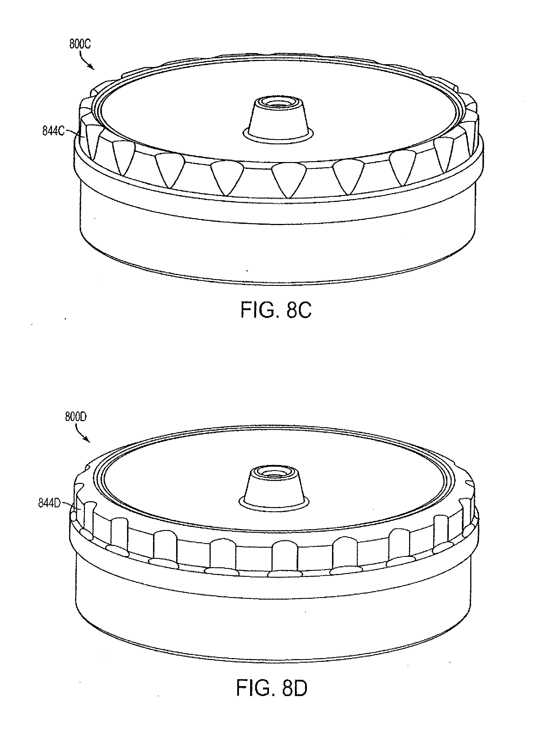
[0063] FIGS. 8A-8E illustrate alternative base molds 800A-800E and respective up-stand geometries 844A-844E according to embodiments of the disclosed subject matter. Thus, this disclosure covers corresponding container bases and in particular up-stand wall configurations formed by these base molds 800A-800E and variations thereof.
[0064] FIG. 10 is a flow chart for a method 1000 according to embodiments of the disclosed subject matter.
[0065] Methods according to embodiments of the disclosed subject matter can include providing a plastic container as set forth herein (S1002). Providing a plastic container can include blow molding or otherwise forming the container. Providing a plastic container also can include packaging, shipping, and/or delivery of a container. Methods can also include filling, for example, hot-filling the container with a product such as described herein, at a temperature as described herein (S1004). After filling, the container can be sealed with a closure such as described herein (S1006). After sealing filling and sealing the container, a base portion of the container can accommodate or act in response to an internal pressure or force in the filled and sealed container such as described herein (S1008). As indicated above, internal pressure within the sealed and filled container can be caused by hot-filling the container, pasteurization processing to the container, retort processing to the container, or cooling processing to the container. The container base portion can accommodate or act responsively as set forth herein based on the internal pressure or force and the particular configuration and construction of the base portion as set forth herein.
[0066] Though containers in the form of wide-mouth jars have been particularly discussed above and shown in various figures, embodiments of the disclosed subject matter are not limited to wide-mouth jars and can include plastic containers of any suitable shape or configuration and for any suitable use, including bottles, jugs, asymmetrical containers, single-serve containers or the like. Also, embodiments of the disclosed subject matter shown in the drawings have circular cross-sectional shapes with reference to a central longitudinal axis. However, embodiments of the disclosed subject matter are not limited to containers having circular cross sections and thus container cross sections can be square, rectangular, oval, or asymmetrical.
[0067] Further, as indicated above, hot-filling below 185.degree. F. (e.g., 180.degree. F.) or above 205.degree. F. is also embodied in aspects of the disclosed subject matter. Pasteurizing and/or retort temperatures above 185.degree., above 200.degree. F., or above 205.degree. F. (e.g., 215.degree. F.) are also embodied in aspects of the disclosed subject matter.
[0068] Containers, as set forth according to embodiments of the disclosed subject matter can be mode of a thermoplastic made in any suitable way, for example, blow molded (including injection) PET, PEN, or blends thereof. Additionally, optionally, containers according to embodiments of the disclosed subject matter can be multilayered, including a layer of gas barrier material, a layer of scrap material, and/or a polyester resin modified for ultra-violet ("UV") light protection or resistance.
[0069] Having now described embodiments of the disclosed subject matter, it should be apparent to those skilled in the art that the foregoing is merely illustrative and not limiting, having been presented by way of example only. Thus, although particular configurations have been discussed herein, other configurations can also be employed. Numerous modifications and other embodiments (e.g., combinations, rearrangements, etc.) are enabled by the present disclosure and are within the scope of one of ordinary skill in the art and are contemplated as falling within the scope of the disclosed subject matter and any equivalents thereto. Features of the disclosed embodiments can be combined, rearranged, omitted, etc., within the scope of the invention to produce additional embodiments. Furthermore, certain features may sometimes be used to advantage without a corresponding use of other features. Accordingly, Applicants intend to embrace all such alternatives, modifications, equivalents, and variations that are within the spirit and scope of the present invention.
* * * * *
D00000
D00001
D00002
D00003
D00004
D00005
D00006
D00007
D00008
D00009
D00010
D00011
D00012

D00013

XML
uspto.report is an independent third-party trademark research tool that is not affiliated, endorsed, or sponsored by the United States Patent and Trademark Office (USPTO) or any other governmental organization. The information provided by uspto.report is based on publicly available data at the time of writing and is intended for informational purposes only.
While we strive to provide accurate and up-to-date information, we do not guarantee the accuracy, completeness, reliability, or suitability of the information displayed on this site. The use of this site is at your own risk. Any reliance you place on such information is therefore strictly at your own risk.
All official trademark data, including owner information, should be verified by visiting the official USPTO website at www.uspto.gov. This site is not intended to replace professional legal advice and should not be used as a substitute for consulting with a legal professional who is knowledgeable about trademark law.