Elliptical Trainer
YANG; Shun-Chi ; et al.
U.S. patent application number 14/755197 was filed with the patent office on 2015-12-31 for elliptical trainer. This patent application is currently assigned to REXON INDUSTRIAL CORP., LTD.. The applicant listed for this patent is REXON INDUSTRIAL CORP., LTD.. Invention is credited to Chun-Huang YANG, Shun-Chi YANG.
| Application Number | 20150375030 14/755197 |
| Document ID | / |
| Family ID | 54929414 |
| Filed Date | 2015-12-31 |


| United States Patent Application | 20150375030 |
| Kind Code | A1 |
| YANG; Shun-Chi ; et al. | December 31, 2015 |
ELLIPTICAL TRAINER
Abstract
An elliptical trainer includes a frame, a linkage unit, a pedal unit and a horizontal damping unit. The frame includes a base bracket, a column and a guiding member. The linkage unit includes a pair of handles axially disposed on and reciprocately movable relative to the column. The pedal unit includes a pair of pedal levers respectively pivotally mounted to the handles. And the horizontal damping unit includes a pair of belts each having a driven end directly connected to one respective handle or pedal lever and a damping force-generating portion located at an opposite end thereof remote from the driven end. By driving the handles or the pedal levers, the damping force-generating portions provide the handles with a damping in horizontal vector and a potential energy for driving the handles to restore.
| Inventors: | YANG; Shun-Chi; (Taichung, TW) ; YANG; Chun-Huang; (Taichung, TW) | ||||||||||
| Applicant: |
|
||||||||||
|---|---|---|---|---|---|---|---|---|---|---|---|
| Assignee: | REXON INDUSTRIAL CORP.,
LTD. Taichung TW |
||||||||||
| Family ID: | 54929414 | ||||||||||
| Appl. No.: | 14/755197 | ||||||||||
| Filed: | June 30, 2015 |
| Current U.S. Class: | 482/52 |
| Current CPC Class: | A63B 22/001 20130101; A63B 21/4047 20151001; A63B 22/0017 20151001; A63B 21/008 20130101; A63B 21/023 20130101; A63B 22/0056 20130101; A63B 21/015 20130101; A63B 22/0664 20130101; A63B 21/0552 20130101; A63B 2022/067 20130101 |
| International Class: | A63B 21/015 20060101 A63B021/015; A63B 22/06 20060101 A63B022/06; A63B 22/00 20060101 A63B022/00; A63B 21/00 20060101 A63B021/00 |
Foreign Application Data
| Date | Code | Application Number |
|---|---|---|
| Jun 30, 2014 | TW | 103122528 |
Claims
1. An elliptical trainer, comprising: a frame comprising a base bracket, a column fixedly mounted at said base bracket, and guiding means connected to said base bracket and spaced from said column at a distance; a linkage unit comprising a pair of handles respectively axially coupled to said column and reciprocately movable relative to said column, each handle comprising a pivot connecting portion located at one end thereof and pivotally connected to said column and a swinging portion located at an opposite end thereof; a pedal unit comprising a pair of pedal levers respectively pivotally connected to said handles, each pedal lever comprising a front end portion pivotally connected to the swinging portion of the corresponding handle and an opposing rear end portion slidable relative to said guiding means; and a horizontal damping unit comprising a pair of elongated strip members, each elongated strip member comprising a driven end located at one end thereof and directly connected to one of said handles and said pedal levers and an opposing damping force-generating portion located at an opposite end thereof and adapted for providing the corresponding handle with a damping in a horizontal vector and rendering a potential energy for driving the associating driven end to restore.
2. The elliptical trainer as claimed in claim 1, further comprising a vertical damping unit mounted at said base bracket of said frame and adapted for providing the rear end portions of said pedal levers of said pedal unit with a damping in a vertical vector.
3. The elliptical trainer as claimed in claim 2, wherein said vertical damping unit comprises a brake wheel mounted at said base bracket, a pair of driving wheels axially pivotally mounted at said base bracket at one lateral side relative to said brake wheel, a transmission member connected between said brake wheel and one said driving wheel, and a crankshaft eccentrically coupled between said driving wheels; said guiding means comprises two axle bearings respectively mounted at two opposite ends of said crankshaft to support said rear end portions of said pedal levers; said brake wheel is adapted for providing the rear end portions of said pedal lever with a damping in said vertical vector.
4. The elliptical trainer as claimed in claim 1, wherein each said elongated strip member of said horizontal damping unit further comprises a belt connected between one respective said handle and one respective said pedal lever; the driven end of each said elongated strip member is located at one end of the associating said belt; the damping force-generating portion of each said elongated strip member is connected between the associating said belt and said frame.
5. The elliptical trainer as claimed in claim as claimed in claim 2, wherein each said elongated strip member of said horizontal damping unit further comprises a belt connected between one respective said handle and one respective said pedal lever; the driven end of each said elongated strip member is located at one end of the associating said belt; the damping force-generating portion of each said elongated strip member is connected between the associating said belt and said frame.
6. The elliptical trainer as claimed in claim as claimed in claim 3, wherein each said elongated strip member of said horizontal damping unit further comprises a belt connected between one respective said handle and one respective said pedal lever; the driven end of each said elongated strip member is located at one end of the associating said belt; the damping force-generating portion of each said elongated strip member is connected between the associating said belt and said frame.
7. The elliptical trainer as claimed in claim 4, wherein said damping generators of said horizontal damping unit are selected from the group of tension springs, elastic strips and hydraulic cylinders.
8. The elliptical trainer as claimed in claim 4, wherein said horizontal damping unit further comprises a pair of damping wheels respectively pivotally mounted at said frame to support the respective said belts of said elongated strip members.
9. The elliptical trainer as claimed in claim as claimed in claim 1, wherein each said elongated strip member of said horizontal damping unit further comprises a belt connected between one respective said handle and one respective said pedal lever; the driven end of each said elongated strip member is located at one end of the associating said belt; the belt of each said elongated strip member comprises a connection end opposite to the associating said driven end; the damping force-generating portion of each said elongated strip member is connected the connection end of the associating said belt.
10. The elliptical trainer as claimed in claim as claimed in claim 2, wherein each said elongated strip member of said horizontal damping unit further comprises a belt connected between one respective said handle and one respective said pedal lever; the driven end of each said elongated strip member is located at one end of the associating said belt; the belt of each said elongated strip member comprises a connection end opposite to the associating said driven end; the damping force-generating portion of each said elongated strip member is connected the connection end of the associating said belt.
11. The elliptical trainer as claimed in claim as claimed in claim 3, wherein each said elongated strip member of said horizontal damping unit further comprises a belt connected between one respective said handle and one respective said pedal lever; the driven end of each said elongated strip member is located at one end of the associating said belt; the belt of each said elongated strip member comprises a connection end opposite to the associating said driven end; the damping force-generating portion of each said elongated strip member is connected the connection end of the associating said belt.
12. The elliptical trainer as claimed in claim 9, wherein said frame further comprises an upright slider guide; said damping force-generating portions of said horizontal damping unit are counterweights linearly movable along said slider guide.
13. The elliptical trainer as claimed in claim 1, wherein said horizontal damping unit further comprises a plurality of guide rollers pivotally mounted at said base bracket of said frame, said pedal levers and said crankshaft; said elongated strip members are tension springs wound around said guide rollers.
14. The elliptical trainer as claimed in claim 2, wherein said horizontal damping unit further comprises a plurality of guide rollers pivotally mounted at said base bracket of said frame, said pedal levers and said crankshaft; said elongated strip members are tension springs wound around said guide rollers.
15. The elliptical trainer as claimed in claim 3, wherein said horizontal damping unit further comprises a plurality of guide rollers pivotally mounted at said base bracket of said frame, said pedal levers and said crankshaft; said elongated strip members are tension springs wound around said guide rollers.
16. The elliptical trainer as claimed in claim 1, further comprising a grip unit and a linking-up unit, said grip unit comprising a pair of grips respectively connected to respective top ends of said handles, said linking-up unit comprising a pivot bar swingeable relative to said column and two links respectively pivotally coupled between two opposite ends of said pivot bar and said handles.
Description
BACKGROUND OF THE INVENTION
[0001] 1. Field of the Invention
[0002] The present invention relates to sports equipment technology and more particularly, to an elliptical trainer.
[0003] 2. Description of the Related Art
[0004] U.S. Pat. No. 7,942,787 discloses an elliptical trainer, entitled "Exercise Machine," which comprises a frame, a pair of handles axially disposed on a column at the frame, a pair of pedals respectively pivotally mounted at respective bottom ends of the handles, and a damping unit mounted at a rear side of the frame. The damping unit comprises a flywheel pivotally mounted at the frame, a crankshaft disposed in a coaxial manner relative to the flywheel, a pair of guide members supported on the two opposite ends of the crankshaft and respectively fixedly connected to respective rear bottom sides of the pedals, a friction wheel axially disposed on one lateral side of the flywheel, and a transmission belt mounted between the flywheel and the friction wheel. By means of stepping on the pedal to impart a force to the pedals, and using the flywheel to rotate the friction wheel in producing a damping in a vertical vector and the guide members to provide the two opposite ends of the crankshaft with a resistance in a horizontal vector, the operator can carry out a stepping motion mode with elliptical trajectory.
[0005] Although the aforesaid prior art elliptical trainer can produce the desired bodybuilding effect, due to the damping unit producing a damping in the horizontal vector by means of surface friction between the guide members and the opposite ends of the crankshaft, a large amount of fines and dust particles can be produced during operation. Further, fines and dust particles can be adhered between the guide members and the two opposite ends of the crankshaft, leading to unsmooth operation.
[0006] Further, each time the damping unit of the elliptical trainer is operated to produce a damping in the horizontal vector, no potential energy will be generated, and the elliptical trainer can simply utilize the inertial force for making the reciprocating motion.
SUMMARY OF THE INVENTION
[0007] The present invention has been accomplished under the circumstances in view. It is the main object of the present invention to provide an elliptical trainer, which uses elongated strip members to produce damping resistance, thus minimizing fines and dust particles and enhancing operation smoothness. Another object of the present invention is to provide an elliptical trainer which provides various different operation modes for producing different damping so that the operator can select different operation modes according to different requirements.
[0008] To achieve these and other objects of the present invention, an elliptical trainer comprises a frame, a linkage unit, a pedal unit and a horizontal damping unit. The frame comprises a base bracket, a column fixedly mounted at the base bracket, and a guiding member connected to the base bracket and spaced from the column at a distance. The linkage unit comprises a pair of handles respectively axially coupled to the column and reciprocately movable relative to the column. Each handle comprises a pivot connecting portion located at one end thereof and pivotally connected to the column, and a swinging portion located at an opposite end thereof. The pedal unit comprises a pair of pedal levers respectively pivotally connected to the handles. Each pedal lever comprises a front end portion pivotally connected to the swinging portion of the respective handle, and an opposing rear end portion slidable relative to the guiding means. The horizontal damping unit comprises a pair of elongated strip members. Each elongated strip member comprises a driven end located at one end thereof and directly connected to one handle or pedal lever, and an opposing damping force-generating portion located at an opposite end thereof and adapted for providing the respective handle with a damping in a horizontal vector and rendering a potential energy for driving the associating driven end to restore.
[0009] The invention achieves the effects that: by directly connecting the driven ends of the elongated strip members of the horizontal damping units to the handles or the pedal levers and using the damping force-generating portions to provide the handles with a damping in a horizontal vector and to impart a potential energy for driving the driven ends to restore, the invention can produce the expected damping effect and effectively reduce the generation of fines and dust particles. Further, the invention provides different operation modes for producing different damping, and thus, the operator can select different operation modes according to different requirements.
BRIEF DESCRIPTION OF THE DRAWINGS
[0010] Other advantages and features of the present invention will be understood by reference to the following in conjunction with the accompanying drawings, in which like reference characters denote like elements of structure.
[0011] FIG. 1 is a perspective view of an elliptical trainer in accordance with a first embodiment of the present invention.
[0012] FIG. 2 is a side elevational view of the elliptical trainer in accordance with the first embodiment of the present invention.
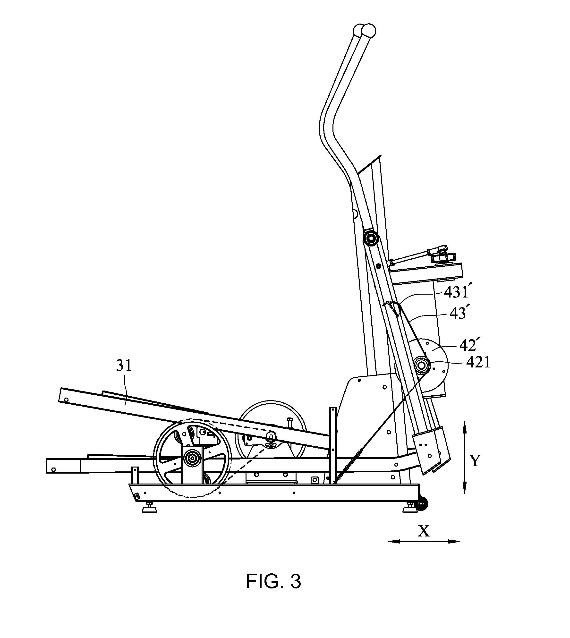
[0013] FIG. 3 is a side elevational view of the elliptical trainer in accordance with a second embodiment of the present invention.
[0014] FIG. 4 is a side elevational view of the elliptical trainer in accordance with a third embodiment of the present invention.
[0015] FIG. 5 is a side elevational view of the elliptical trainer in accordance with a fourth embodiment of the present invention.
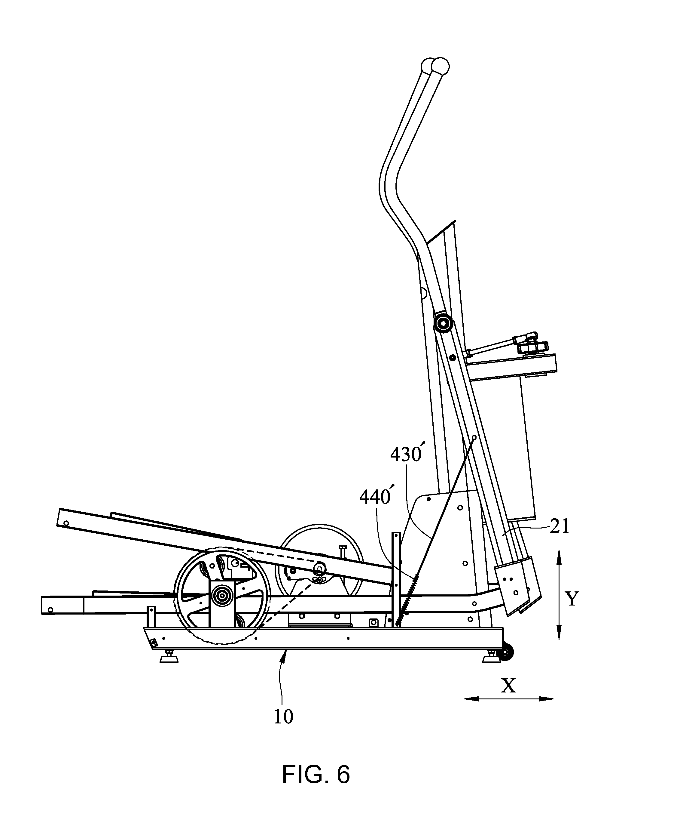
[0016] FIG. 6 is a side elevational view of the elliptical trainer in accordance with a fifth embodiment of the present invention.
[0017] FIG. 7 is a side elevational view of the elliptical trainer in accordance with a sixth embodiment of the present invention.
[0018] FIG. 8 is a side elevational view of the elliptical trainer in accordance with a seventh embodiment of the present invention.
[0019] It should be noted that the drawing figures are not necessarily drawn to scale, but instead are drawn to provide a better understanding of the components thereof, and are not intended to be limiting in scope, but rather to provide exemplary illustrations. It should further be noted that the figures illustrate exemplary embodiments of the present invention and the components thereof, and in no way limits the structures, configurations and components thereof according to the present disclosure.
DETAILED DESCRIPTION OF THE INVENTION
[0020] Referring to FIGS. 1 and 2, an elliptical trainer in accordance with a first embodiment of the present invention is shown. The elliptical trainer comprises a frame 10, a linkage unit 20, a pedal unit 30, a horizontal damping unit 40, a vertical damping unit 50, a grip unit 60, and a linking-up unit 70.
[0021] The frame 10 comprises a base bracket 11, a column 12 fixedly mounted at a front side of the base bracket 11, and a pair of axle holders 13 fixedly mounted at an opposing rear side of the base bracket 11 and spaced from the column 12 at a predetermined distance. The column 12 comprises a transverse axle 121 disposed near a top end thereof, an extension bar 122 spaced below the transverse axle 12, a front panel 123 downwardly extended from the extension bar 122, and two rollers 124 symmetrically pivotally mounted at two opposite lateral sides of the front panel 123.
[0022] The linkage unit 20 comprises a pair of handles 21 respectively coupled to two opposite ends of the transverse axle 121 in an axial direction relative to the column 12 and reciprocately movable relative to the column 12. Each handle 21 comprises a pivot connecting portion 211 and a swinging portion 212 respectively formed on two ends thereof. The pivot connecting portion 211 is pivotally connected to one end of the transverse axle 121. A detent member 213 is spaced between the pivot connecting portion 211 and the swinging portion 212.
[0023] The pedal unit 30 comprises a pair of pedal levers 31 respectively pivotally connected to the handles 21, and a pair of pedals 32 respectively mounted at the pedal levers 31. Each pedal lever 31 has a front end portion 311 and a rear end portion 312 opposite to the front end portion 311 formed thereon. The front end portion 311 is pivotally connected to the swinging portion 212 of the corresponding handle 21. The pedals 32 are respectively mounted at the rear end portions 312 of the pedal levers 31.
[0024] The horizontal damping unit 40 comprises a pair of elongated strip members 41, and a pair of damping wheels 42 mounted at the frame 10. Each elongated strip member 41 comprises a belt 43 directly connected to one respective handle 21, and a damping force-generating portion 44 connected between the belt 43 and the frame 10. The belt 43 comprises a driven end 431 connected to the detent member 213 of the corresponding handle 21, and a connection end 432 opposite to the driven end 431. The damping wheels 42 are mounted at the front panel 123, each comprising a gear 421. In this embodiment, the belts 43 of the elongated strip members 41 are respectively wound around the respective rollers 124 and the respective damping wheels 42. Each belt has a single-sided gear rack 433 meshed with the corresponding gear 421. The damping force-generating portion 44 of each elongated strip member 41 is disposed at one end of the respective belt 43 which is opposite to the driven end 431. In this embodiment, the damping force-generating portion 44 of each elongated strip member 41 is connected to the connection end 432 of the associating belt 43, and is adapted for providing the respective handle 21 a damping in a horizontal vector X and a potential energy for driving the respective handle to restore. In this embodiment, the damping force-generating portions 44 of the elongated strip members 41 are tension springs. However, elastic strips or hydraulic cylinders can be used as substitutes.
[0025] The vertical damping unit 50 is adapted for providing the rear end portions 312 of the pedal levers 31 of the pedal unit 30 with a damping in a vertical vector Y. The vertical damping unit 50 comprises a brake wheel 51 mounted at the base bracket 11, a pair of driving wheels 52 mounted at the base bracket 11 and disposed at one side relative to the driving wheel 52, a transmission member 53 coupled between the brake wheel 51 and one of the driving wheels 52, and a crankshaft 54 eccentrically coupled between the two driving wheels 52. The brake wheel 51 provides the rear end portions 312 of the pedal levers 31 a damping in the vertical vector Y. The frame 10 further comprises guiding members 14 connected to the base bracket 11 through the crankshaft 54. In this embodiment, the two guiding members 14 are axle bearings respectively mounted at two opposite ends of the crankshaft 54. The rear end portions 312 of the pedal levers 31 are slidably supported on the two axle bearings of the guiding members 14.
[0026] The grip unit 60 comprises two grips 61 respectively connected to the handles 21 above the transverse axle 121.
[0027] The linking-up unit 70 comprises a pivot bar 71 pivotally connected to a distal end of the extension bar 122 and swingeable relative to the column 12. The two links 72 are respectively pivotally coupled between two opposite ends of the pivot bar 71 and the two handles 21.
[0028] When the operator wishes to operate the elliptical trainer in accordance with the aforesaid component parts and to perform a sliding operation mode, the crankshaft 54 of the vertical damping unit 50 is almost not driveable. When the operator's feet are respectively stepped on the pedals 32 to impart a force to the pedals 32 and the pedal levers 31 forwardly and horizontally, the front end portions 311 of the pedal levers 31 force against the swinging portions 212 of the handles 21, such that the handles 21 are turned about the axis that extends through the pivot connecting portions 211. At this time, with the arrangement of the linking-up unit 70, the pedal levers 31, the handles 21 and the grips 61 are driven to produce coordinate actions.
[0029] When the handles 21 are moved back and forth, the detent members 213 are forced to stop against the driven ends 431 of the belt bodies 43 of the elongated strip members 41 of the horizontal damping unit 40. As the belts 43 of the elongated strip members 41 extend over the rollers 124, they can be stopped smoothly. Further, because the belts 43 of the elongated strip members 41 are respectively meshed with the respective gears 421 by means of the single-sided gear racks 433 thereof, they can positively drive the damping wheels 42 to rotate and to further generate a damping in the horizontal vector X. When the handle 21 is biased forward, the respective damping force-generating portion 44 is pulled to generate another damping in the horizontal vector X (at this time, the respective damping force-generating portion 44 is stretched for preserving an elastic restoring force). Therefore, using the total damping in the horizontal vector X enables the operator to achieve the purpose of training the muscles of the legs. When the force applied by the operator disappears, the restoring force of the damping force-generating portion 44 is released to return the driven end 431 of the belt 43 of the respective elongated strip member 41 of the horizontal damping unit 40, i.e., the respective handle 21 can be biased backwards. Thus, the present invention greatly enhances the operator's operational rhythm sensations.
[0030] When the operator intends to carry out the operation mode of the stepping with elliptical trajectory, the operator can use two legs to impart force forwardly along the horizontal direction and downwardly along the vertical direction to the pedals 32 and the pedal levers 31. At this time, the front end portion 311 of the pedal lever 31 is forced against the swinging portion 212 of the respective handle 21, causing the respective handle 21 to be turned about the axis that extends through the pivot connecting portions 211 of the handles 21. When the handle 21 is turned about the axis that extends through the pivot connecting portions 211 of the handles 21, the respective belt 43 and damping force-generating portion 44 of the horizontal damping unit 40 will be deterred, thus generating a damping in the horizontal vector X. Further, subject to the functioning of the pedal levers 31 to alternatively impart a downward pressure to the two ends of the crankshaft 54 and the functioning of the vertical damping unit 50, a damping in the vertical vector Y can be created.
[0031] Except the two operation modes described above, the operator can perform a simple up and down stepping operation mode. When the operator intends to perform the up and down stepping operation mode, the operator imparts a force vertically downward to the pedals 32 and the pedal levers 31. At this time, the pedal levers 31 and pedals 32 of the pedal unit 30 will alternatively impart a downward pressure to the two ends of the crankshaft 54, and thus, a damping in the vertical vector Y can be created subject to the functioning of the vertical damping unit 50. During the stepping operation mode, the handles 21 are almost immovable, and the horizontal damping unit 40 creates almost no damping in the horizontal vector X. Thus, when the operator performs a different operation mode, a different damping can be created. Therefore, the operator can selectively perform different operation modes according to different requirements, such as, the operation mode of up and down stepping with back and forth elliptical trajectory, sliding operation mode, or simple up and down stepping operation mode.
[0032] Subject to the feature that the handles 21 can be driven to move the belts 43 directly and the feature that the single-sided gear rack 433 of the belt 43 is meshed with the respective gear 421, the horizontal damping unit 40 can drive the damping wheel 42 to rotate and to further produce a damping in the horizontal vector X. Further, subject to the feature that the damping force-generating portion 44 can be deterred to generate another damping in the horizontal vector X, the invention can produce the expected damping effect. Further, because there is no friction damping, the invention effectively reduces the generation of dust particles. When the force applied by the operator disappears, the elastic restoring force of the damping force-generating portion 44 can impart a potential energy for driving the respective driven end 431 to restore.
[0033] Referring to FIG. 3, an elliptical trainer in accordance with a second embodiment of the present invention is shown. This second embodiment is substantially similar to the aforesaid first embodiment with the exception that the rollers are removed, and the belts 43' are directly wound around the respective damping wheels 42' and meshed with the respective gears 421. Thus, when operating the pedals 32 and the pedal levers 31, a damping resistance in the horizontal vector X and the vertical vector Y can be rendered to the handles 21, and an elastic potential energy for driving the driven end 431' to restore. Therefore, this second embodiment can achieve the same effects as the aforesaid first embodiment.
[0034] Referring to FIG. 4, an elliptical trainer in accordance with a third embodiment of the present invention is shown. This third embodiment is substantially similar to the aforesaid first embodiment with the exception that the driven ends 431'' of the belts 43'' are directly connected to the respective pedal levers 31, and the belts 43'' are directly wound around the respective damping wheels 42 and meshed with the respective gears 421. Thus, when operating the pedal levers 31, a damping resistance in the horizontal vector X and the vertical vector Y can be rendered to the handles 21, and for driving the respective driven end 431'' to restore. Therefore, this third embodiment can achieve the same effects as the aforesaid first embodiment.
[0035] Referring to FIG. 5, an elliptical trainer in accordance with a fourth embodiment of the present invention is shown. This fourth embodiment is substantially similar to the aforesaid first embodiment with the exception that the driven ends 431''' of the belts 430 are directly connected to the handles 21, and, the damping wheels 420 are pivotally mounted at the base bracket 11. Therefore, this fourth embodiment can achieve the same effects as the aforesaid first embodiment.
[0036] Referring to FIG. 6, an elliptical trainer in accordance with a fifth embodiment of the present invention is shown. This fifth embodiment is substantially similar to the aforesaid first embodiment with the exception that the damping wheels are removed, the belts 430' are directly connected to the respective handles 21, and, the damping force-generating portions 440' are directly connected to the frame 10. Therefore, this fifth embodiment can achieve the same effects as the aforesaid first embodiment.
[0037] Referring to FIG. 7, an elliptical trainer in accordance with a sixth embodiment of the present invention is shown. This sixth embodiment is substantially similar to the aforesaid first embodiment with the exception that the damping wheels are removed. In addition to the two rollers 124', the frame 10' further comprises a pair of guide rod-shaped upright slider guides 125'. The damping force-generating portions 440'' of the horizontal damping unit 400'' are counterweights respectively linearly movable along the slider guides 125'. Subject to the feature that the handles 21 can deter the horizontal damping unit 400'' when they are biased, the effect of the gravity weight of the horizontal damping unit 400'' imparts the handles 21 with a damping in the horizontal vector X and the effect of the gravity weight of the horizontal damping unit 400'' imparts a potential energy for driving the driven end 431'''' to restore. Thus, this sixth embodiment can achieve the same effects as the aforesaid first embodiment.
[0038] Referring to FIG. 8, an elliptical trainer in accordance with a seventh embodiment of the present invention is shown. This seventh embodiment is substantially similar to the aforesaid first embodiment with the exception that the horizontal damping unit 4 comprises a pair of belts 401 and a plurality of guide rollers 402 respectively pivotally mounted at the base bracket 11 of the frame 10, the pedal levers 31 and the crankshaft 54. The elongated strip members 401 are tension springs, each having a driven end 403 directly connected to the respective handle 21. The damping force-generating portions 404 are respectively mounted at the opposite ends of the respective elongated strip members 401 remote from the respective driven ends 403. The elongated strip members 401 are wound around the guide rollers 402 with the respective damping force-generating portions 404 respectively connected to the base bracket 11 of the frame 10. Thus, this seventh embodiment can achieve the same effects as the aforesaid first embodiment.
[0039] Although particular embodiments of the invention have been described in detail for purposes of illustration, various modifications and enhancements may be made without departing from the spirit and scope of the invention. Accordingly, the invention is not to be limited except as by the appended claims.
* * * * *
D00000
D00001
D00002
D00003
D00004
D00005
D00006
D00007
D00008
XML
uspto.report is an independent third-party trademark research tool that is not affiliated, endorsed, or sponsored by the United States Patent and Trademark Office (USPTO) or any other governmental organization. The information provided by uspto.report is based on publicly available data at the time of writing and is intended for informational purposes only.
While we strive to provide accurate and up-to-date information, we do not guarantee the accuracy, completeness, reliability, or suitability of the information displayed on this site. The use of this site is at your own risk. Any reliance you place on such information is therefore strictly at your own risk.
All official trademark data, including owner information, should be verified by visiting the official USPTO website at www.uspto.gov. This site is not intended to replace professional legal advice and should not be used as a substitute for consulting with a legal professional who is knowledgeable about trademark law.