Exercise Apparatus
WHITE; ADAM ; et al.
U.S. patent application number 13/169975 was filed with the patent office on 2012-12-27 for exercise apparatus. Invention is credited to ADAM WHITE, John White.
| Application Number | 20120329620 13/169975 |
| Document ID | / |
| Family ID | 47362384 |
| Filed Date | 2012-12-27 |


View All Diagrams
| United States Patent Application | 20120329620 |
| Kind Code | A1 |
| WHITE; ADAM ; et al. | December 27, 2012 |
EXERCISE APPARATUS
Abstract
The present invention comprises an adjustable exercise apparatus safe and effective for full body weight exercises, movements, stretches, and training. The present invention comprises a system for holistic body weight training such as yoga, martial arts, stretching, physical therapy, rehabilitation, and physical exercise training. The exercise apparatus comprises linking elements comprising elongated connectors, closed connectors, and openable connectors. The adjustable exercise apparatus comprises at least a dual anchor system which enables a user to safely exercise without impinging the apparatus' linking elements which are parallel to the user's sagittal plane.
| Inventors: | WHITE; ADAM; (Rio Rancho, NM) ; White; John; (Rio Rancho, NM) |
| Family ID: | 47362384 |
| Appl. No.: | 13/169975 |
| Filed: | June 27, 2011 |
| Current U.S. Class: | 482/131 |
| Current CPC Class: | A63B 7/02 20130101; A63B 23/1227 20130101; A63B 2210/50 20130101; A63B 23/1236 20130101; A63B 2225/093 20130101; A63B 21/00069 20130101; A63B 21/0555 20130101; A63B 21/0557 20130101; A63B 21/002 20130101; A63B 21/16 20130101; A63B 21/0442 20130101; A63B 2225/09 20130101; A63B 71/02 20130101; A63B 21/4035 20151001; A63B 2023/006 20130101; A63B 21/1636 20130101; A63B 21/1663 20130101; A63B 21/4043 20151001; A63B 21/068 20130101; A63B 21/151 20130101; A63B 23/1218 20130101 |
| Class at Publication: | 482/131 |
| International Class: | A63B 21/00 20060101 A63B021/00 |
Claims
1. A system for full body weight training comprising: an anchor system comprising at least two anchors wherein said anchors are attachably disposed at a plurality of locations; at least two un-openable connectors; at least two first elongated connectors wherein said elongated connectors are disposed within buckles at one end; at least two securable openable connectors; at least two second elongated connectors disposed attachably to at least two said openable connectors at one end and said buckles at another end; and at least two handle systems connected to said at least two openable connectors.
2. The anchors of claim 1 wherein said anchors comprise one end of said first elongated connectors.
3. The handle system of claim 1 wherein said handle system comprises: a handle; and a handle connector.
4. The handle of claim 3 wherein said handle comprises a curved handle.
5. The un-openable connector of claim 1 wherein said connector comprises a ring.
6. The elongated connectors of claim 1 wherein said connectors comprise webbing.
7. The system for full body weight training of claim 1 wherein said un-openable connectors are attachably disposed to said first elongated connector via stitching
8. The securable openable connector of claim 1 wherein said connector comprises a carabiner.
9. The handle system of claim 3 further comprising a foot strap disposed within said handle.
10. The handle system of claim 3 further comprising: an ergonomic shaped padded conformable EVO handle; and a heatable gel filling.
11. The system for full body weight training of claim 1 wherein said system is alignedly disposed parallel to a user's body's sagittal plane.
12. A system for training comprising: adjustable dual anchors attachably disposed on a structure; a plurality of elongated connectors comprising three sets of two connectors wherein the first set comprises anchors, the second set comprises elongated connectors, and the third set comprises handle connectors; securable adjustable connectors comprising carabiners; and a handle system comprising a curved handle.
13. A system for full body weight training comprising: an anchor system comprising at least two anchors wherein said anchors are attachably disposed at a plurality of locations; at least two first securable openable connectors; at least two first elongated connectors attachably disposed to said at least two said first openable connectors at one end; at least two second elongated connectors attachably disposed to at least two said first openable connectors at one end and at least two second openable connectors at a second end; and at least two handle systems connected to said at least two second openable connectors.
14. The anchors of claim 13 wherein said anchors comprise an end of said first elongated connectors.
15. The handle system of claim 13 wherein said handle system comprises: a handle; and a handle connector.
16. The handle of claim 15 wherein said handle comprises a curved handle.
17. The elongated connectors of claim 13 wherein said connectors comprise webbing.
18. The elongated connectors of claim 13 wherein said connectors comprise substantially inelastic straps.
19. The securable openable connector of claim 13 wherein said connector comprises a carabiner.
20. The handle system of claim 13 further comprising a foot strap disposed within said handle.
Description
BACKGROUND OF THE INVENTION
Field of Invention
[0001] The present invention relates to an apparatus and method of full body weight exercising and movement, and more particularly to an apparatus comprising a system of easily configurable connectors for performing a wide variety of movements, exercises, stretches, martial arts moves, and physical therapies, and the method of using the apparatus.
[0002] Providing resistance via stretching elastic bands or using inelastic straps to exercise the arms, legs, and torso is known as resistance training. Currently, exercisers use resistance exercise devices of the prior art to exercise because the devices provide a resistance to the movement of the user's arms, legs, or torso. Resistance is normally provided by working one muscle against another muscle or against gravity, and may include using elastic bands to provide an increased resistance force. The usefulness of the devices currently known in the art depends in part on the ease with which a user performs different types of exercises, the range or number of exercises that are performed with the device, the degree that the device's configuration allows for proper and safe form, and the ease with which different users adjust the device according to his or her height, weight, strength, and/or physical limitations.
[0003] Elastic bands when used stretch from a fixed position to provide increased resistance to the muscles being exercised. Currently used elastic bands are portable and available in a variety of sizes and resistance levels, but variations in length are currently limited, thus limiting the diversity of exercises that can be performed. Additionally, different users or exercisers may not be able to use the same device design because of variations of user stature and weight as well as variations in user strength. Such devices, in order to be useful for a wide variety of users, must be comprised of many different bands of varying length and resistance, but currently are not.
[0004] The inherent resistance of elastic devices increases with increased displacement. Shortcomings of this type of exercise equipment include decreasing displacement raises the potential for the elastic device to snap and elastic devices are not designed for weight larger than the force applied by the user's muscles. This limits the usefulness of these kinds of elastic devices.
[0005] Inelastic straps that are not adjustable, but which can be fixed in between a door jamb and a door overcome some of the limitations of elastic devices. A fixed-length strap attached to a door via a pulley system allows a user to exercise by moving his or her arms in opposite directions. A pair of fixed length straps attached to a door limits the user on the exercises performed because the straps are not adjustable. An adjustable inelastic strap with handles on each side, anchored to a single anchor point anchored to a door or bar overcomes some of the limitations of elastic bands and non-adjustable inelastic straps. This kind of device allows inelastic straps to be adjusted to varying lengths to accommodate users' variable stature, weight, and strength. Nearly zero resistance to the full body weight of the user is thought to be achievable.
[0006] Some limitations of an adjustable inelastic device with a single anchor point include the tendency of the single strap to slide through the single anchor point and cause the user to lose balance, causing the user to be put in a position of potential physical harm. Users with a physical injury on a side of his or her body have increased risk of off-balance slippage. Users exercising with a single anchor point device are not able to load transfer, or shift weight, from one side of the body to another, for example, the exerciser is unable to perform a load transfer pushup. Another limiting factor of a single anchor point is the user is not able to position his/her body correctly under the "upside-down V" shape created by the straps attached to a single anchor point in order to perform full-weight body dips, pull-ups, or pushups using proper and safe form.
[0007] The adjustable inelastic strap devices presently on the market all include a similar handle design. Current handle design limits use of both hands and feet during exercise due to the minimal size and design of the handle. The current design also limits the user's comfort. The average opening area of handles currently known in the art is approximately only 12.5 square inches, which limits the range of motion of a user and forces the user to come into contact with the straps and the handle and limits the exercises a user can perform correctly and safely.
[0008] The adjustable inelastic strap devices currently known also consist of an exposed foot strap that emerges from the bottom of the handle. The handle design thus limits the size of a user's foot in order for that user to exercise using the foot strap. The design currently known in the art also inhibits the user from performing foot-based exercises without using the foot strap. The use of cam buckles in the adjustable inelastic strap devices currently known is a limiting factor because the cam buckles slip when too much user weight is applied, leading to increased potential for bodily injury as well as increasing the instability and insecurity of these adjustable inelastic strap devices.
[0009] It is also not possible (again due to the single anchor point) to use an adjustable inelastic strap device to provide support and assistance while training to improve flexibility and increase range of motion. Additionally, users cannot use only one handle during exercise with current adjustable inelastic strap devices because the devices consist of only one anchor point and one long strap that slides through the single point. A user simply cannot remove a handle during exercise. A user also cannot place, at the same time, both of his or her hands or feet into one handle to exercise. Also because of the single anchor, the adjustable inelastic strap devices currently known cannot accommodate wide, broad or obese users. The "upside-down V" configuration due to the single anchor inhibits the user when performing full-weight body dips. The straps extend across the user's shoulders, thus mandating that the user be placed in a contraindicated position when performing the exercise. Many times it is also uncomfortable for the user as well.
[0010] Because of the general poor design, but more specifically, because of the single anchor point design of the adjustable inelastic strap devices presently known in the art, these devices are not sufficiently stable to be used during physical therapy training. Load transferring is not possible due to the slipping potential of the strap through the single anchor point when a patient is, for example, re-learning how to walk and implementing moving stable parallel bars to increase a patient's core strength. Because of the single anchor point design of the adjustable inelastic strap devices presently known, the straps cannot be crossed when a user attempts to perform exercises. Because of the single anchor point cannot be set to fixed offset positions to perform exercises and physical therapy movements.
[0011] There is thus a need for an exercise apparatus that remains adjustable but ensures stability and safety of the user, is comfortable and non-inhibiting for the user when he or she is exercising, stretching, performing martial arts moves, or undergoing physical therapy. There is a need for an exercise apparatus that is easily and safely adjustable so that it provides a variable resistance and a method of providing a complete workout for any user. There is a need for a method of exercise comprising making adjustments that accommodate a wide range of types of exercises and also a wide variety of user stances, and that provides resistance to the user's motions that are both useful and versatile and accommodating to a specific user's individual needs and anatomy. In addition, there is a need to provide such an apparatus that is adaptable and comfortable for all types of users, as well as being inexpensive, durable and safe. In addition there is a need for an exercise apparatus designed for total body weight and body resistance exercises that safely and without inhibiting the user's movements supports a user's full body weight.
[0012] The exercise apparatus and method of exercise of the present invention fulfills all of the above listed needs and addresses all of the above mentioned deficiencies.
SUMMARY
[0013] The present invention comprises a system for full body weight training comprising an anchor system comprising at least two anchors wherein the anchors are attachably disposed at a plurality of locations; at least two un-openable connectors attachably disposed to the first elongated connector via stitching; at least two first elongated connectors wherein the elongated connectors are disposed within buckles at one end; at least two securable openable connectors; at least two second elongated connectors disposed attachably to at least two the openable connectors at one end and the buckles at another end; and at least two handle systems connected to the at least two openable connectors.
[0014] The system for full body weight training of the present invention is alignedly disposed parallel to a user's body's sagittal plane.
[0015] The anchors comprise one end of the first elongated connectors. The handle system comprises a handle and a handle connector. The handle comprises a curved handle. The handle system further comprises a foot strap disposed within the handle. The handle system further comprises an ergonomic shaped padded conformable EVO handle and a heatable gel filling.
[0016] The un-openable connector comprises a ring. The elongated connectors comprise webbing. The securable openable connector comprises a carabiner.
[0017] Another embodiment of the present invention further comprises a system for training comprising adjustable dual anchors attachably disposed on a structure; a plurality of elongated connectors comprising three sets of two connectors wherein the first set comprises anchors, the second set comprises elongated connectors, and the third set comprises handle connectors; securable adjustable connectors comprising carabiners; and a handle system comprising a curved handle.
[0018] Another embodiment of the present invention further comprises a system for full body weight training comprising an anchor system comprising at least two anchors wherein the anchors are attachably disposed at a plurality of locations; at least two first securable openable connectors; at least two first elongated connectors attachably disposed to said at least two said first openable connectors at one end; at least two second elongated connectors attachably disposed to at least two said first openable connectors at one end and at least two second openable connectors at a second end; and at least two handle systems connected to said at least two second openable connectors.
[0019] In this embodiment, the anchors comprise one end of the first elongated connectors. The handle system comprises a handle and a handle connector. The handle comprises a curved handle. The handle system further comprises a foot strap disposed within the handle. The handle system further comprises an ergonomic shaped padded conformable EVO handle and a heatable gel filling.
[0020] The elongated connectors preferably comprise webbing or alternately comprise substantially inelastic straps. The securable openable connector comprises a carabiner.
BRIEF DESCRIPTION OF THE DRAWINGS
[0021] The accompanying drawings, which are incorporated into and form a part of the specification, illustrate one or more embodiments of the present invention and, together with the description, serve to explain the principles of the invention. The drawings are only for the purpose of illustrating one or more preferred embodiments of the invention and are not to be construed as limiting the invention. In the drawings:
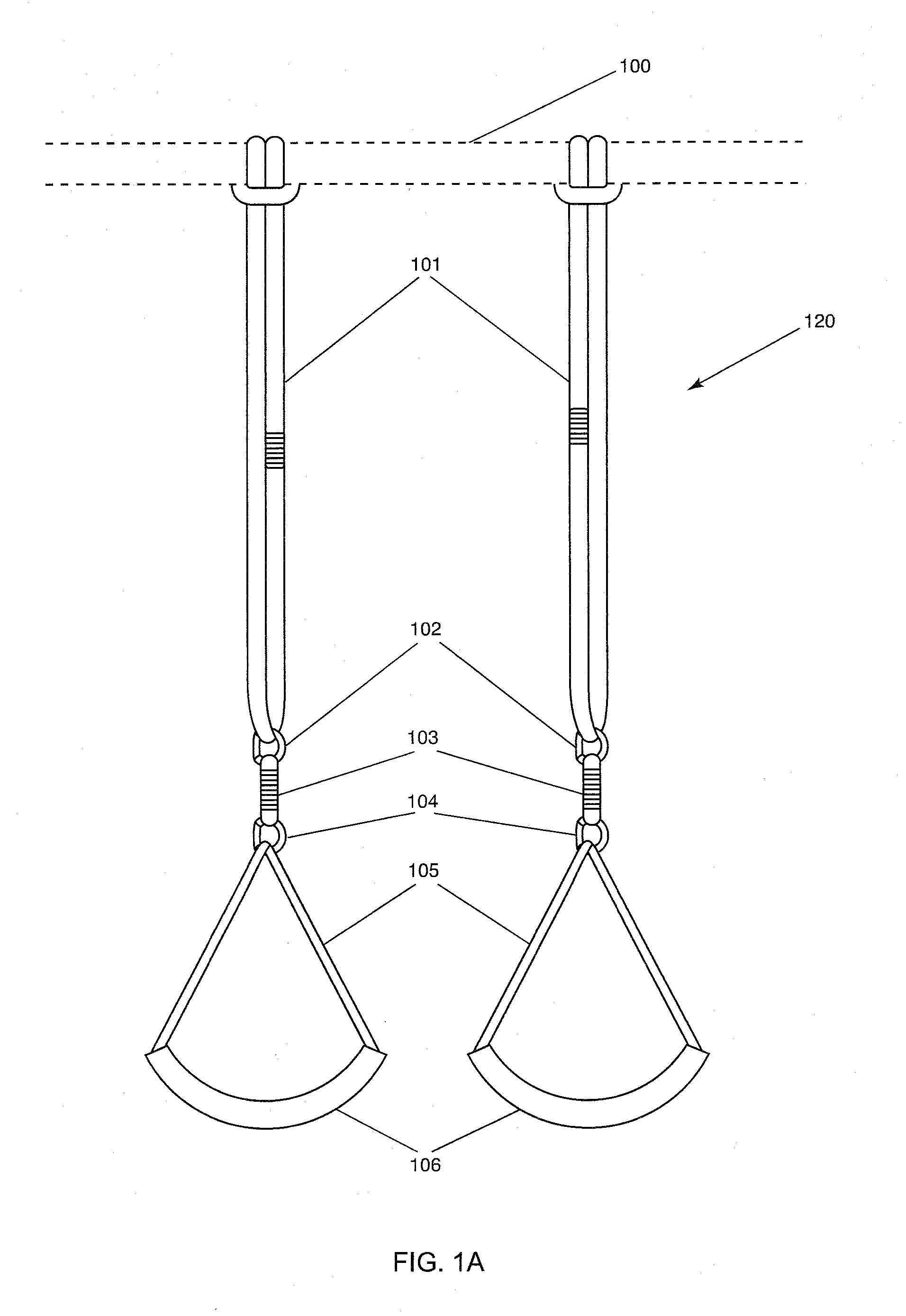
[0022] FIG. 1A is an illustration of a front view of one embodiment of the exercise apparatus of the present invention comprising continuous looped elongated connectors;
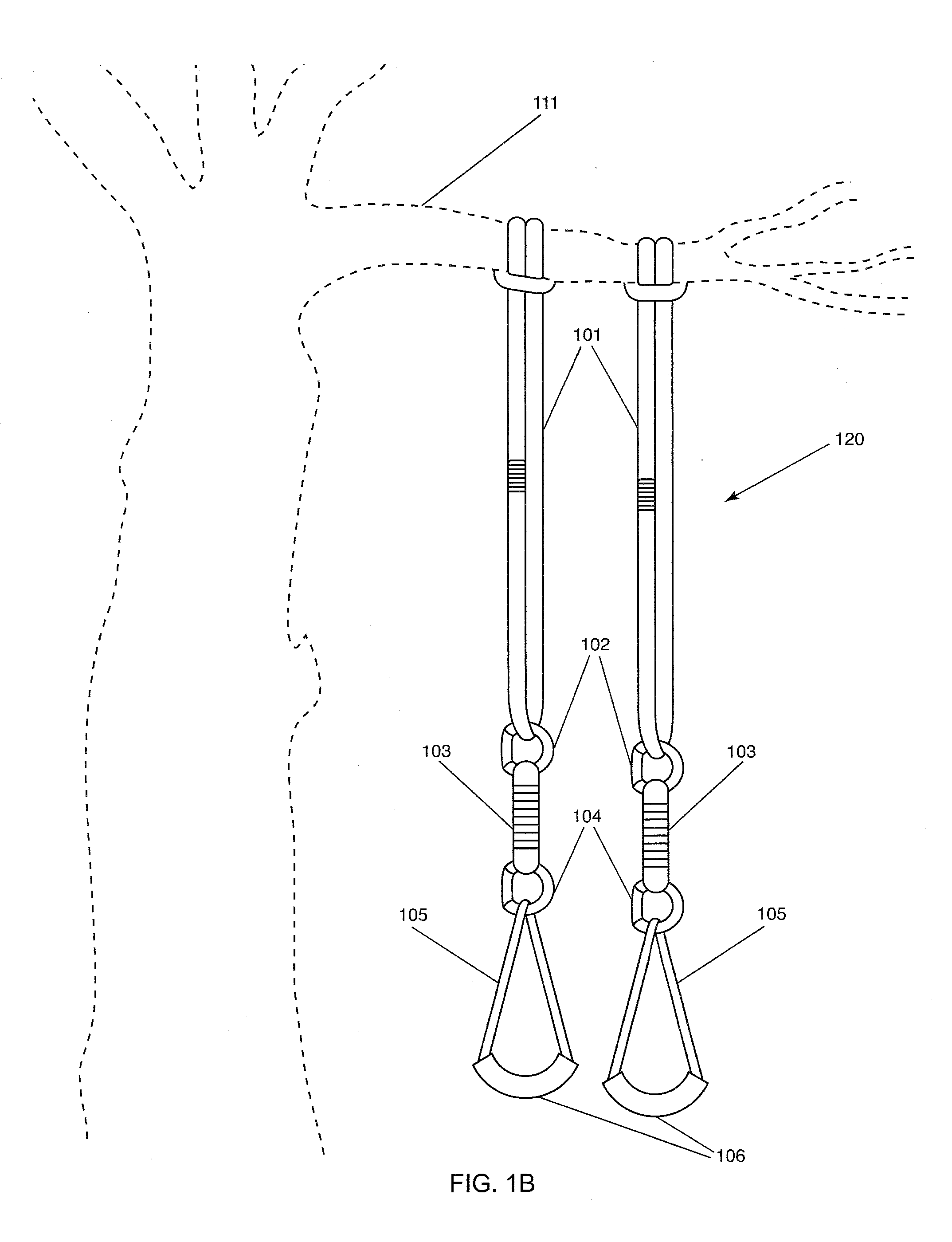
[0023] FIG. 1B is an illustration of the embodiment of FIG. 1A dually anchored to a tree limb;
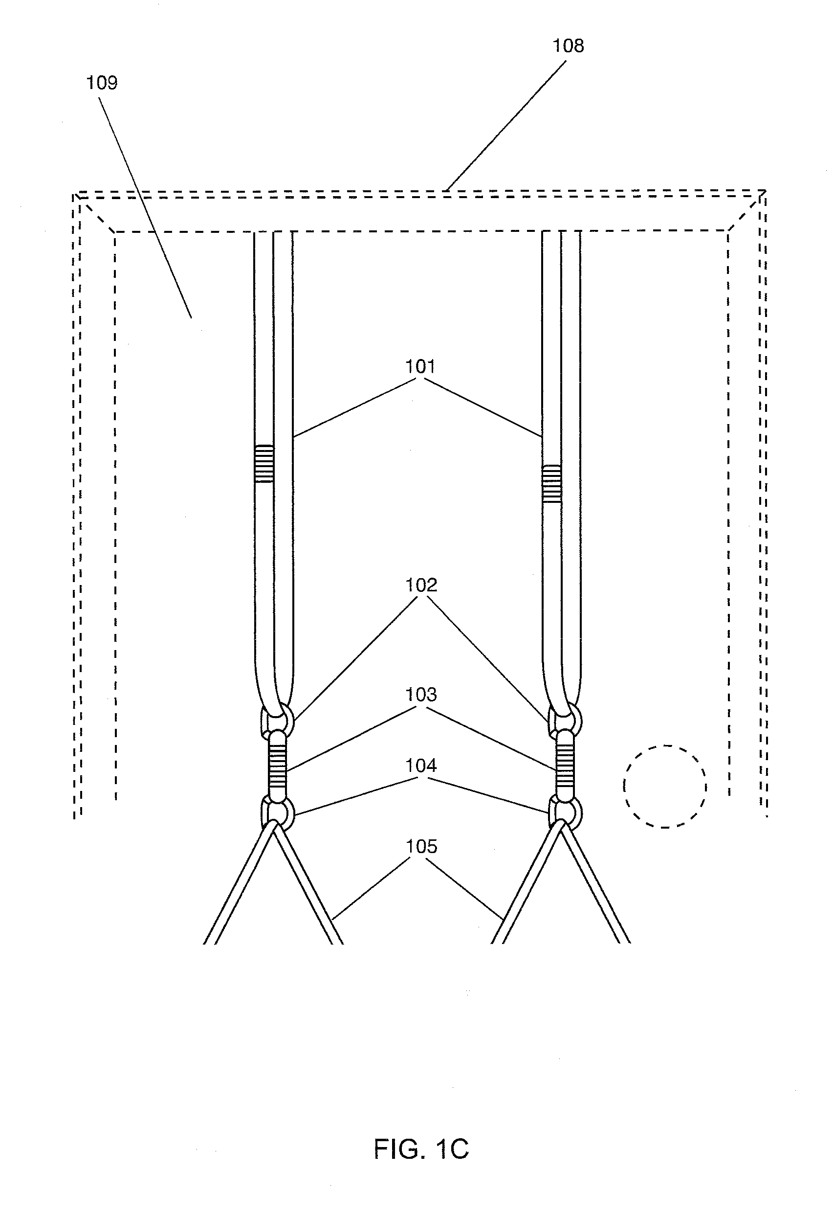
[0024] FIG. 1C is a front view detail of the embodiment illustrated in FIG. 1A dually anchored to a door;
[0025] FIG. 1D is an rear view illustration of the embodiment illustrated in FIG. 1A anchored to a door;
[0026] FIG. 2A is an illustration of a two-ended elongated connector comprising loops on both ends;
[0027] FIG. 2B is a front view of the elongated connector of FIG. 2A looped over a bar and connected to a handle system;
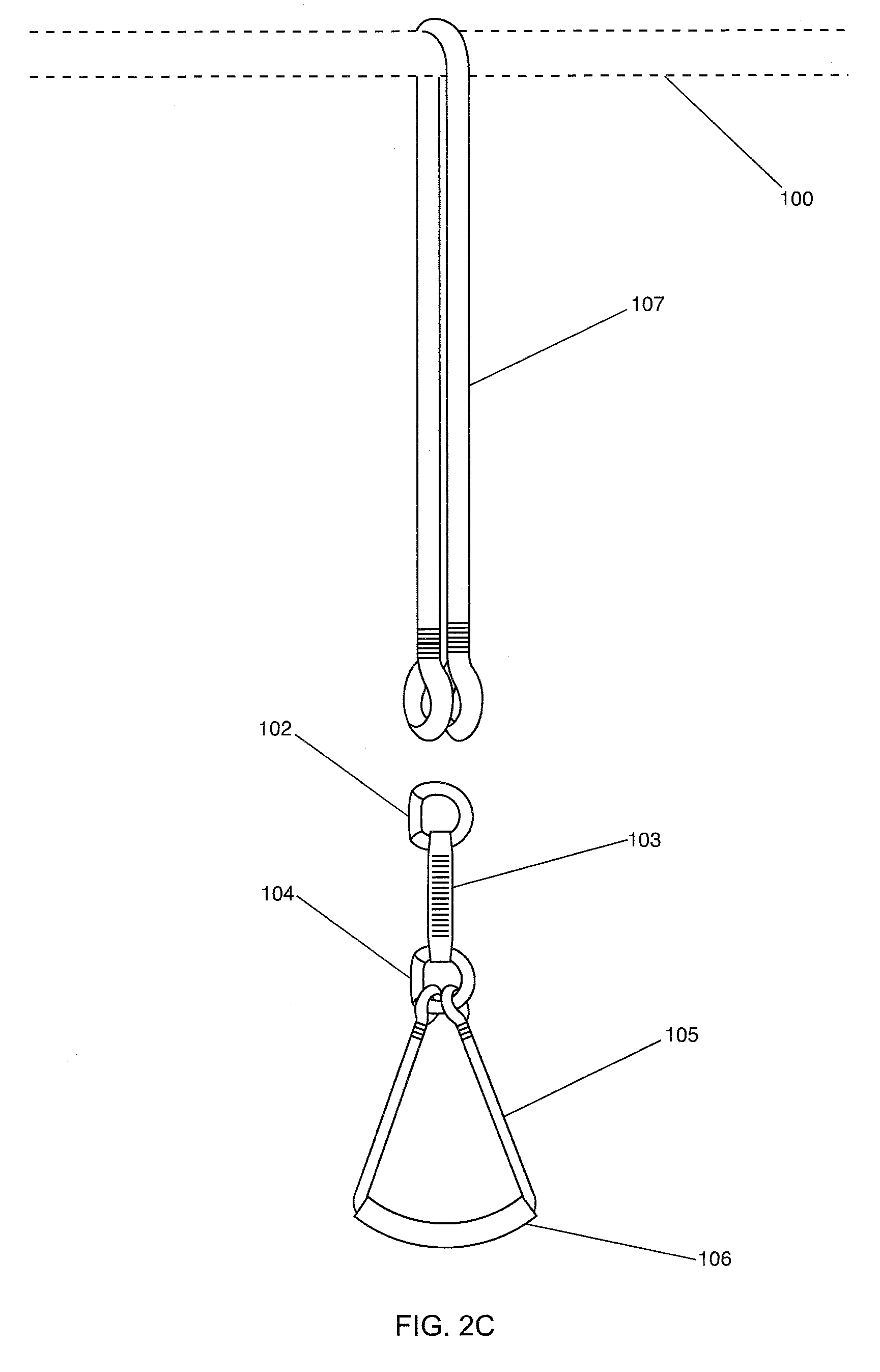
[0028] FIG. 2C is a front view of the elongated connector of FIG. 2A looped over a bar and disconnected to a handle system;
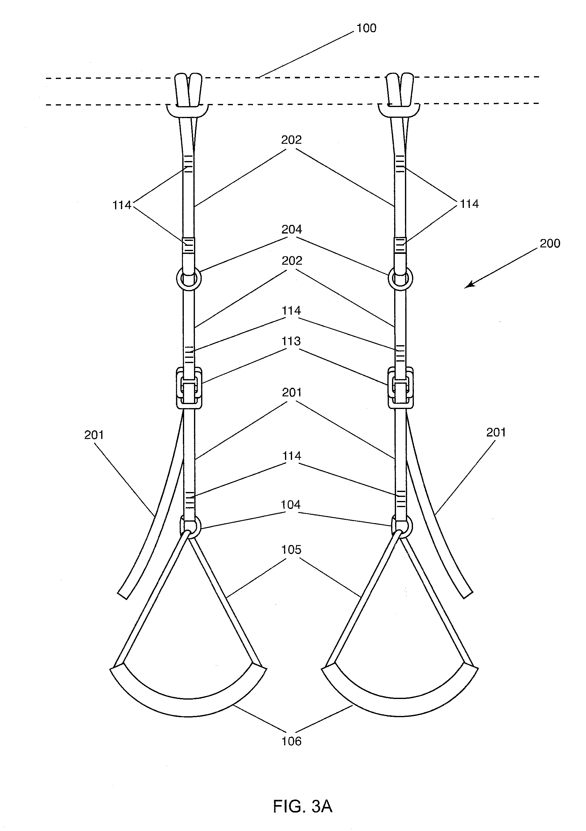
[0029] FIG. 3A illustrates a front view of a preferred embodiment of the exercise apparatus comprising dual anchors;
[0030] FIG. 3B is a side view of the preferred embodiment of the exercise apparatus illustrated in FIG. 3A;
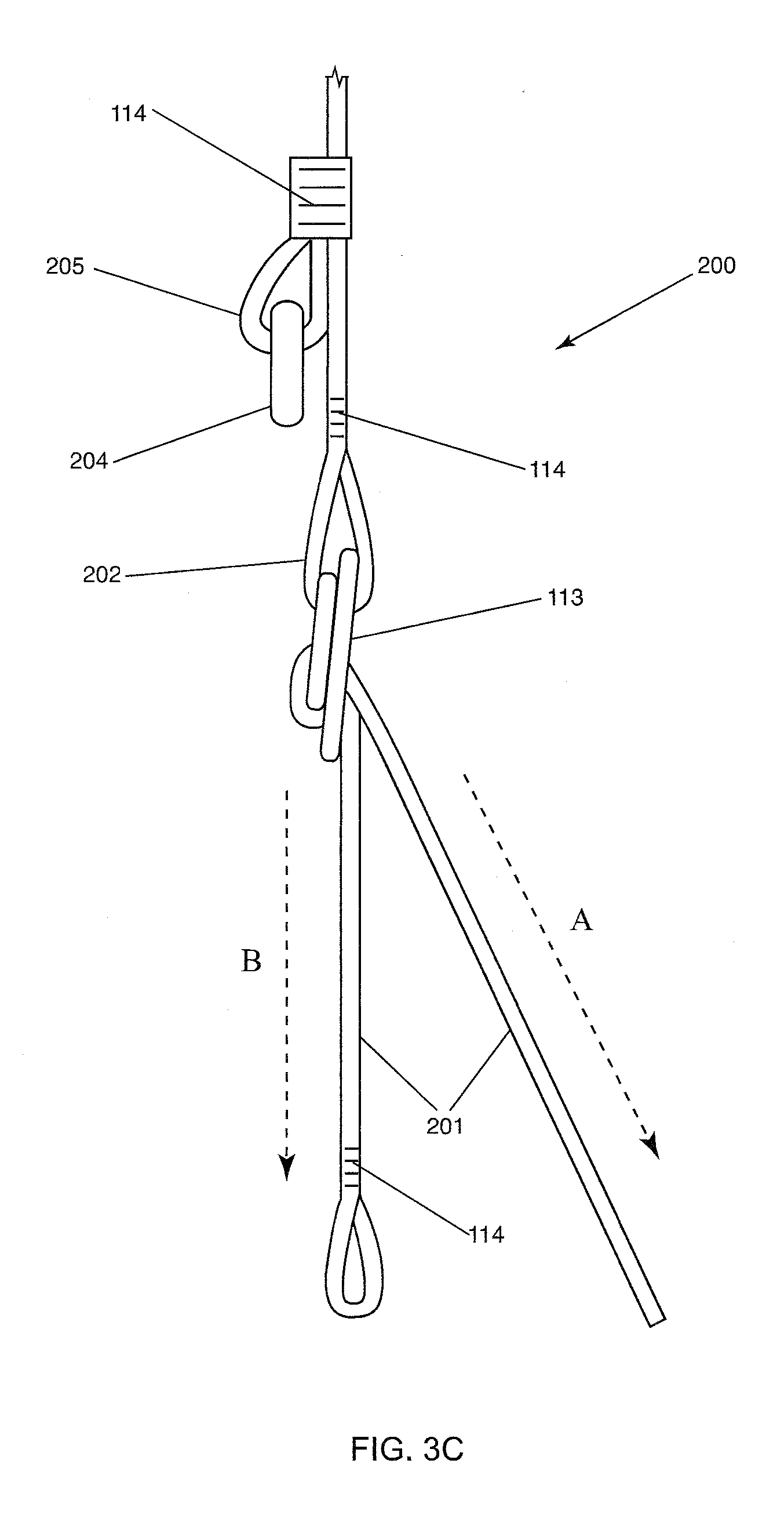
[0031] FIG. 3C illustrates an enlarged detail of the preferred embodiment illustrated in FIG. 3B;
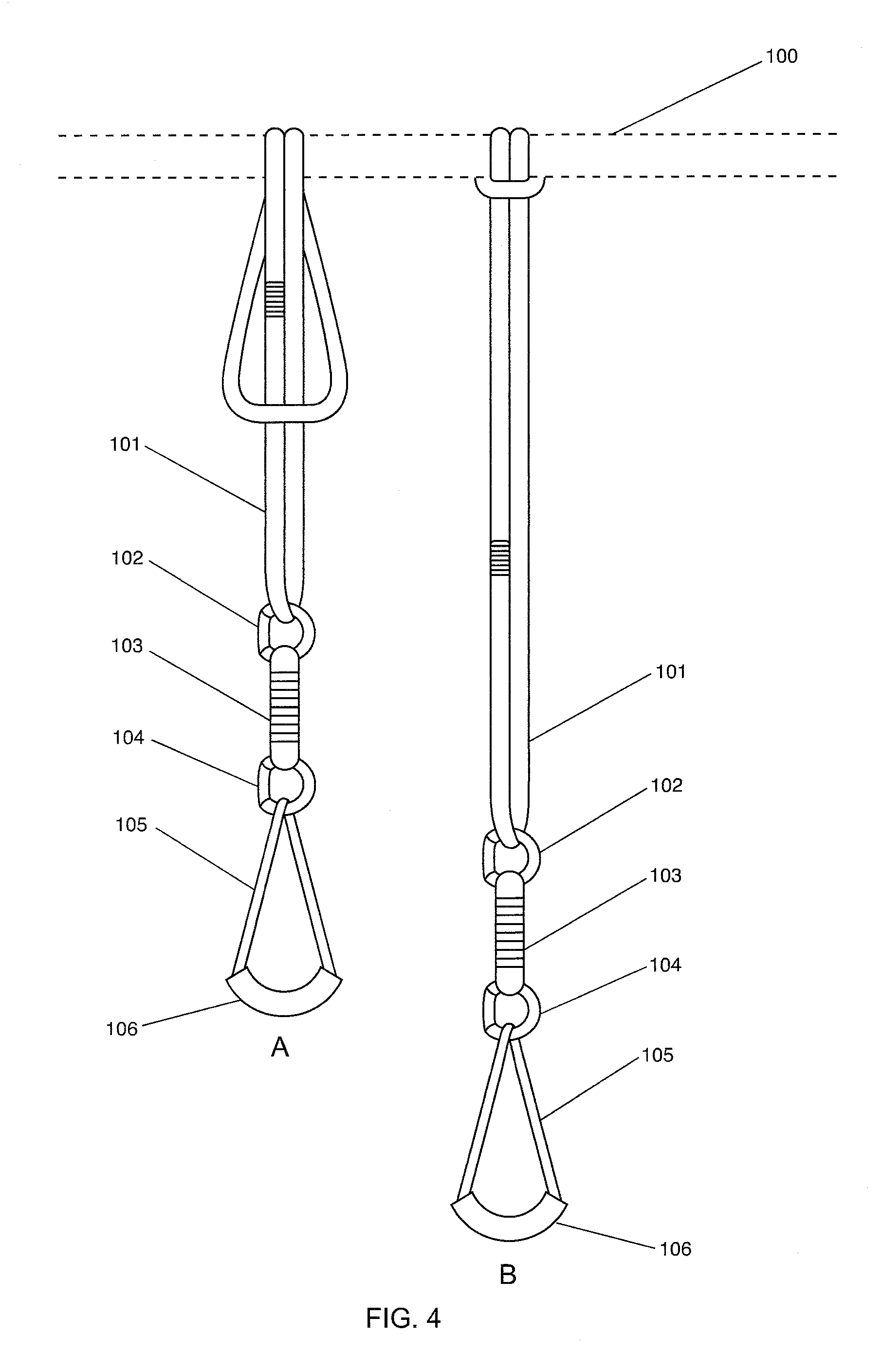
[0032] FIG. 4A illustrates the initial configuration of the exercise apparatus illustrated in FIG. 1A at full extension prior to being secured;
[0033] FIG. 4B illustrates the initial configuration setting of the exercise apparatus illustrated in FIG. 1B used at full extension after being secured;
[0034] FIG. 5A illustrates an alternate configuration of the exercise apparatus illustrated in FIG. 1A at approximately half of its full extension prior to being anchored;
[0035] FIG. 5B illustrates an alternate configuration of the exercise apparatus illustrated in FIG. 1A at approximately half of its full extension after being tightened and anchored;
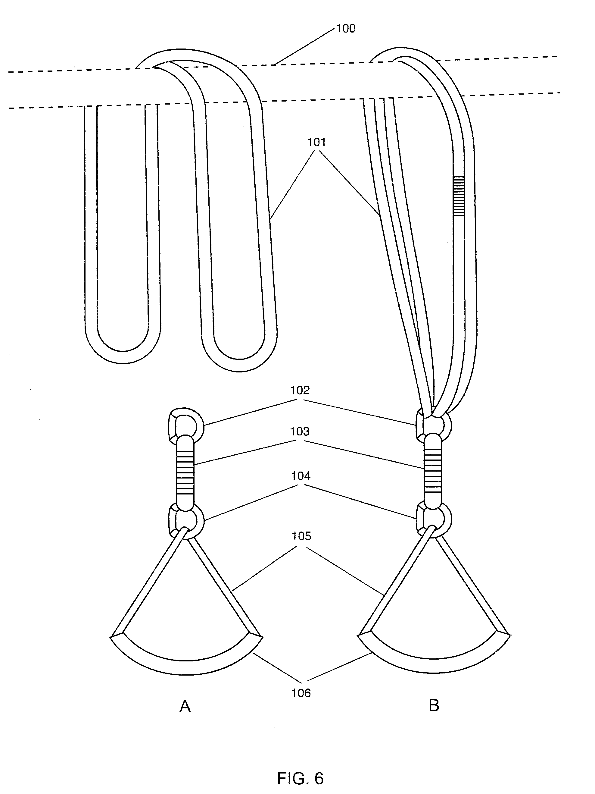
[0036] FIG. 6A illustrates an alternate configuration of the exercise apparatus illustrated in FIG. 1A prior to clipping in the handle and 6B illustrates an alternate configuration of the exercise apparatus after clipping in the handle;
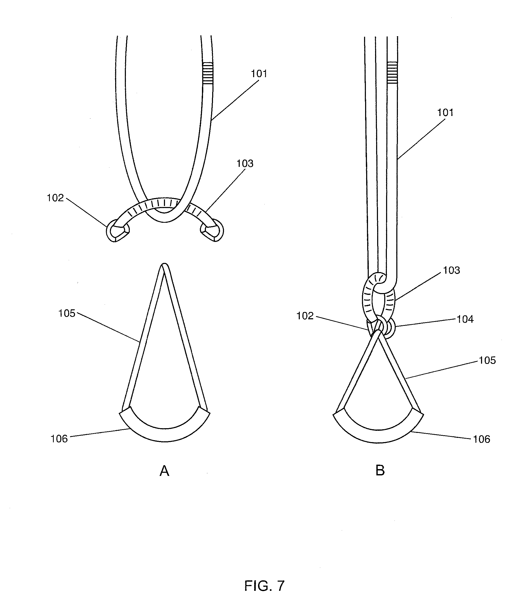
[0037] FIG. 7A and FIG. 7B illustrate an alternate configuration of the exercise apparatus illustrated in FIG. 1A prior to and after the handle is anchored;
[0038] FIGS. 8A and 8B illustrate an alternate configuration of the embodiment of the present invention illustrated in FIG. 1A prior to and after the handle is anchored;
[0039] FIG. 9 illustrates an alternate configuration of the handle of the present invention illustrating foot straps;
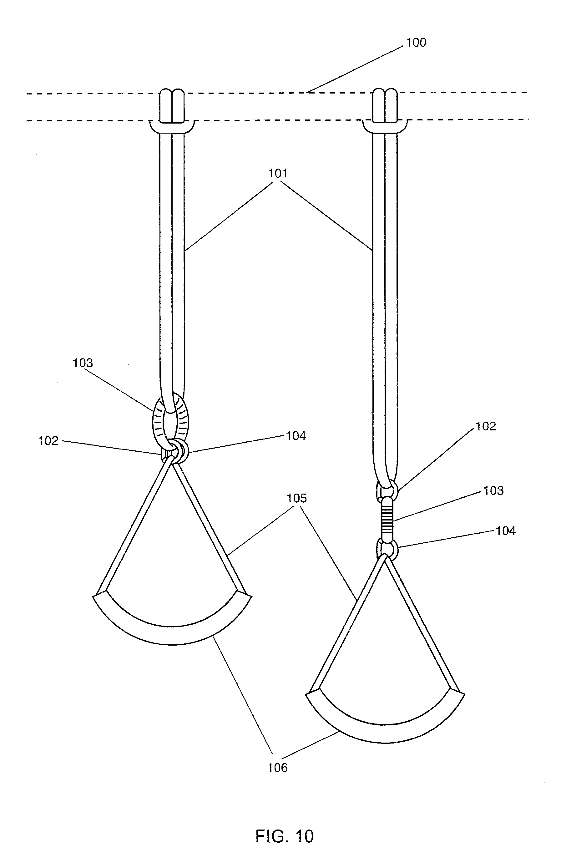
[0040] FIG. 10 illustrates two alternate configurations of the present invention;
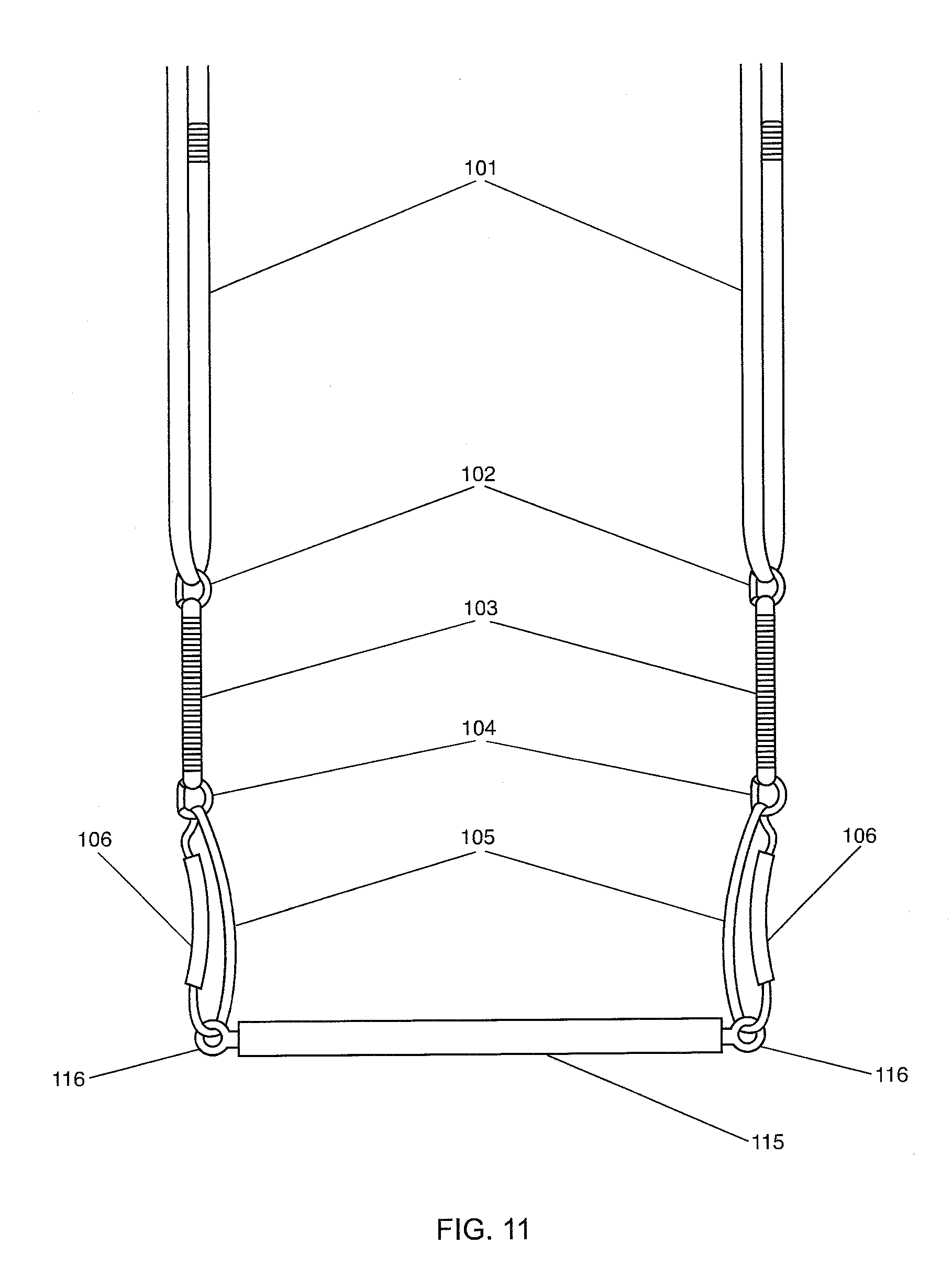
[0041] FIG. 11 illustrates an additional embodiment of the exercise apparatus comprising a crossbar;
[0042] FIG. 12 illustrates another embodiment of the exercise apparatus comprising a straight handle;
[0043] FIG. 13 illustrates an additional embodiment of the exercise apparatus comprising a W bar;
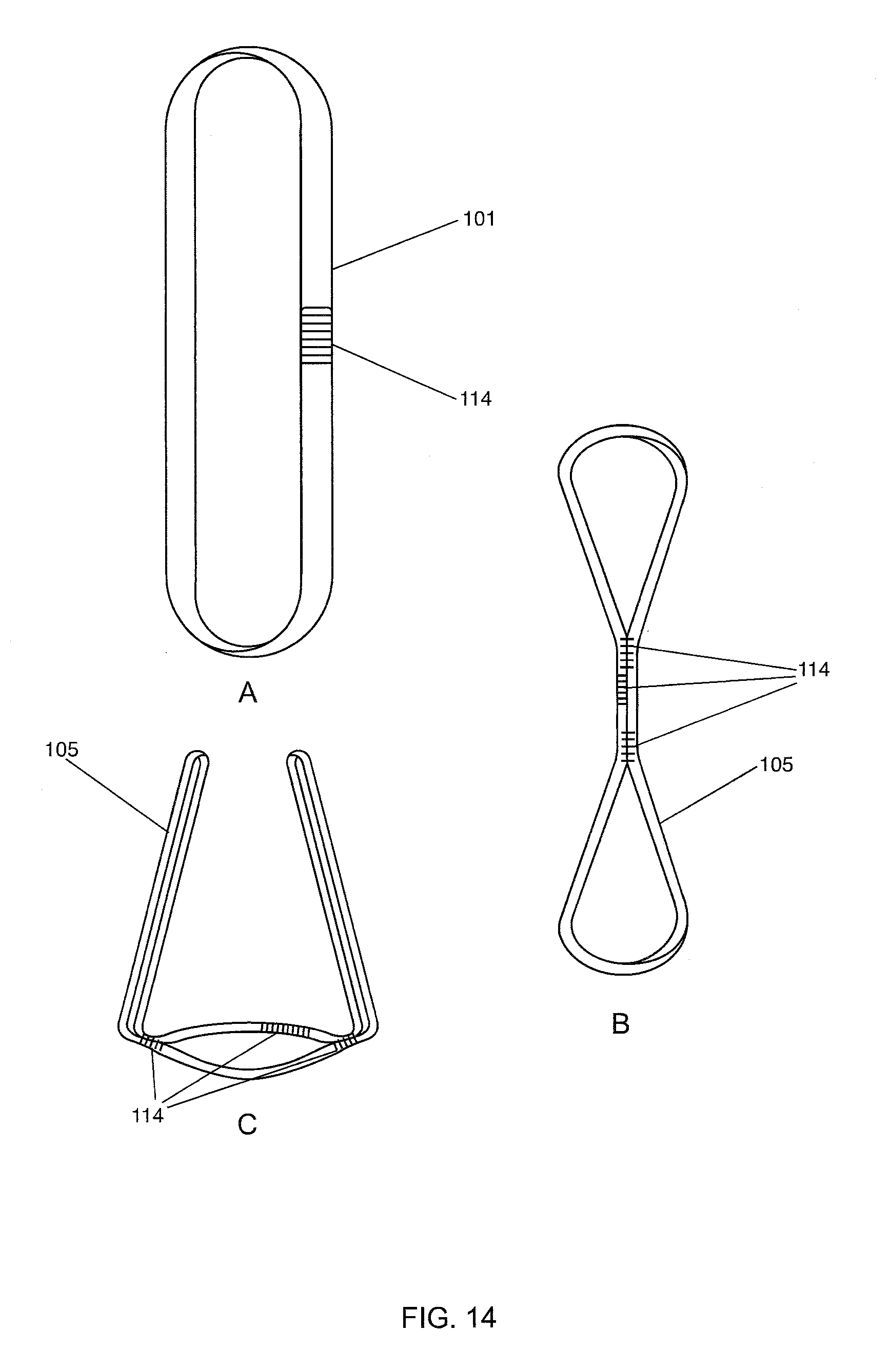
[0044] FIGS. 14A, 14B, and 14C illustrate embodiments of the present invention comprising a plurality of stitch patterns;
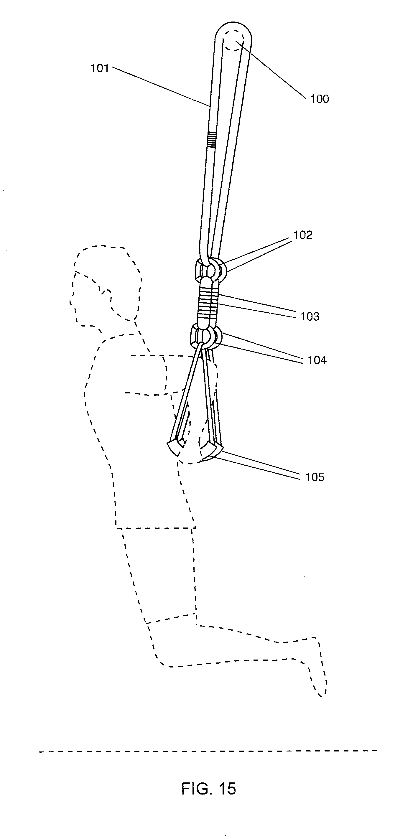
[0045] FIG. 15 illustrates an exerciser performing a full weight body dip while using the dual anchors of the embodiment of the present invention illustrated in FIG. 1A;
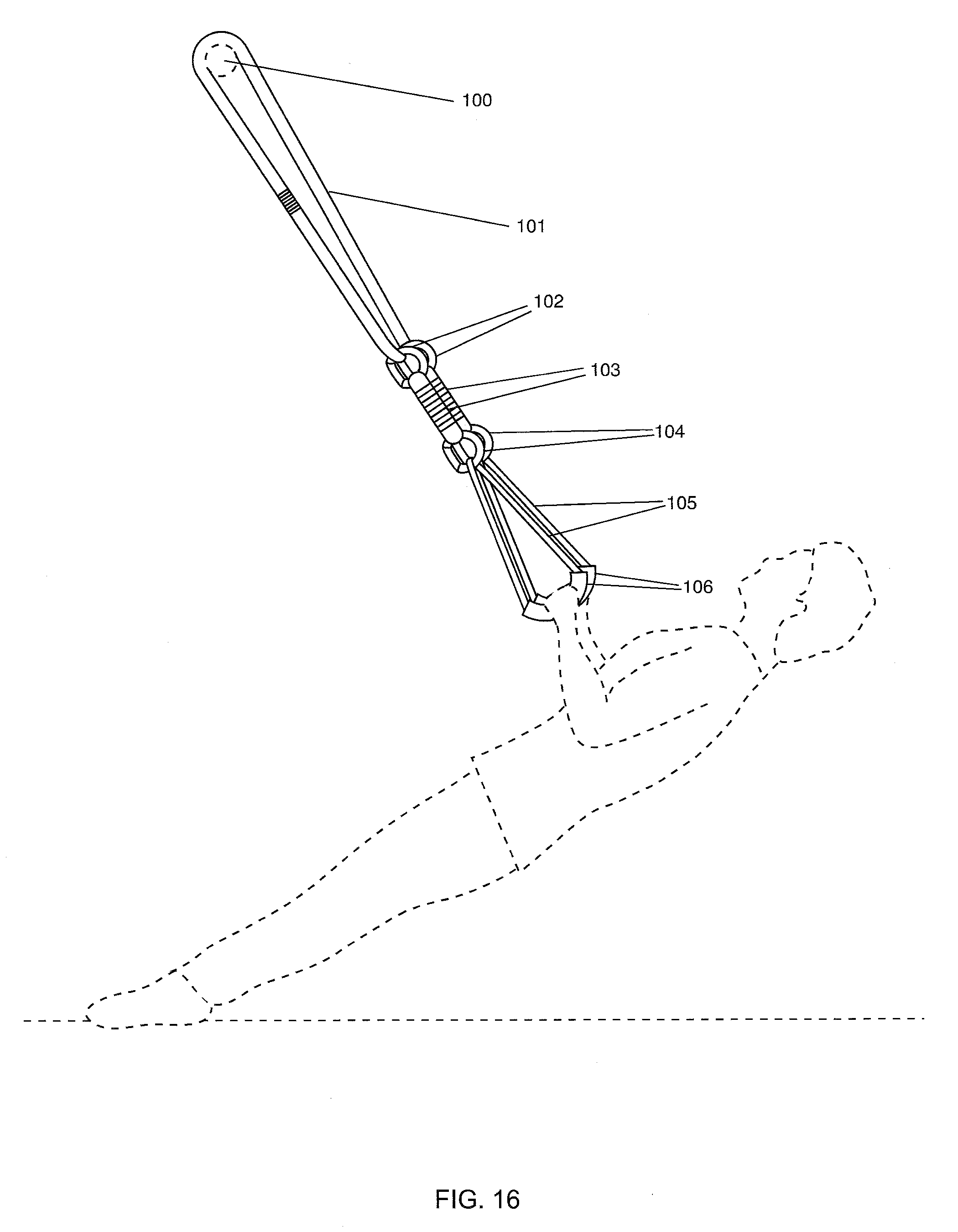
[0046] FIG. 16 illustrates an exerciser performing a high row movement while using the dual anchors of the embodiment of the present invention illustrated in FIG. 1A;
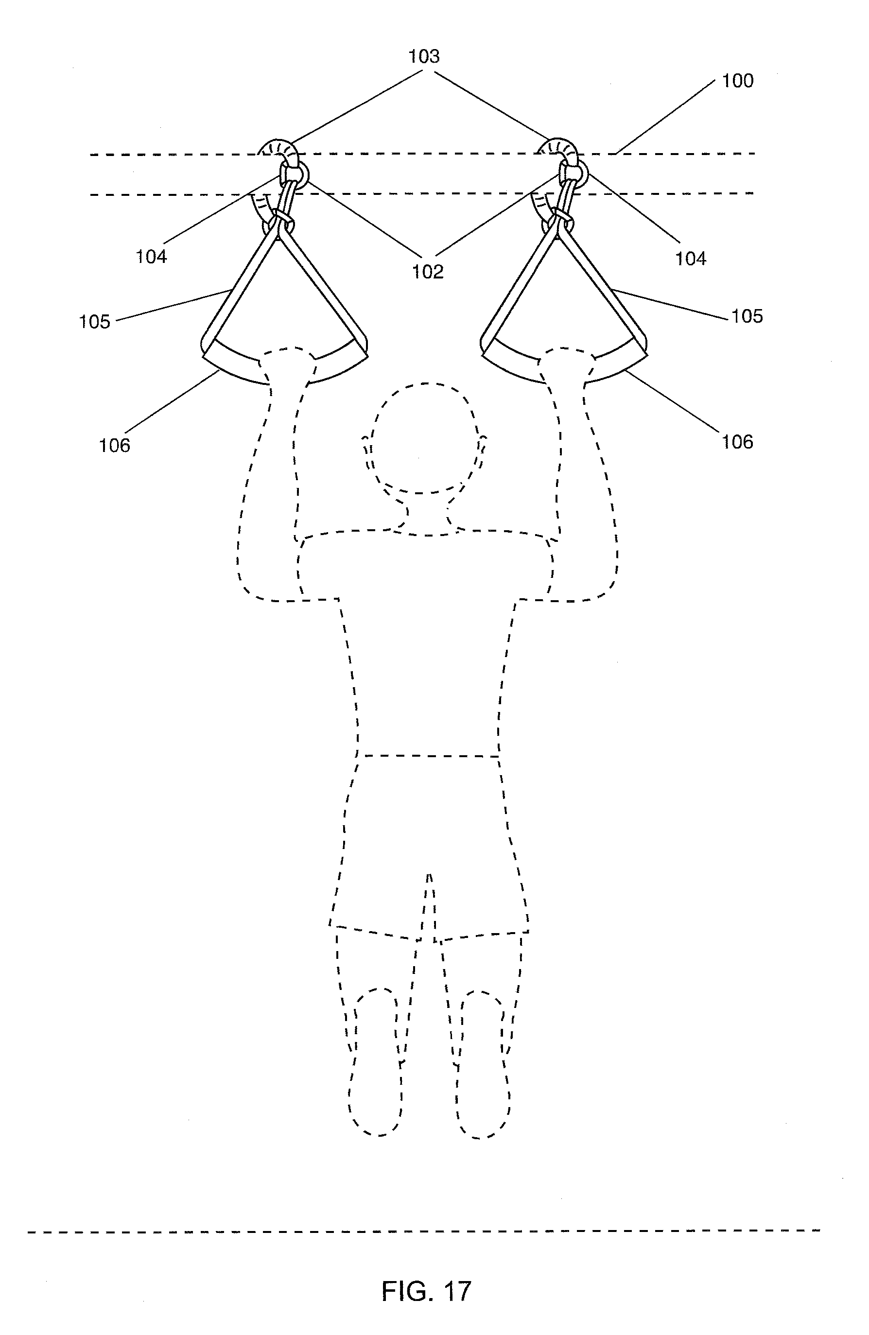
[0047] FIG. 17 illustrates an exerciser using the dual anchors of the embodiment of the present invention illustrated in FIGS. 8A and 8B;
[0048] FIG. 18 is an illustration of an exerciser using the embodiment of FIG. 9;
[0049] FIG. 19 is an illustration of an exerciser performing a load transfer row exercise using the configuration illustrated in FIGS. 8A and 8B;
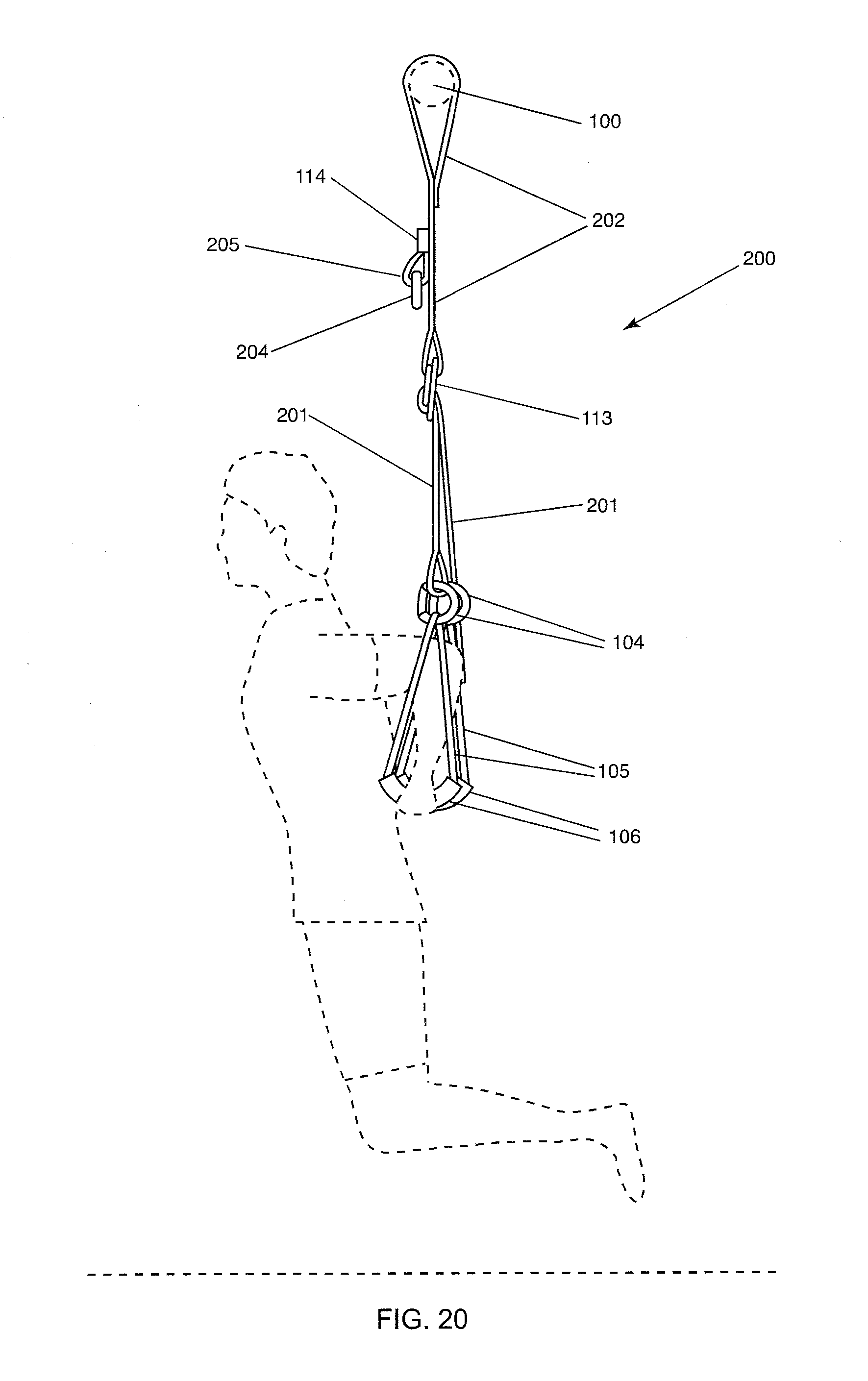
[0050] FIG. 20 is an illustration of an exerciser using the dual anchors of the embodiment illustrated in FIGS. 3A-C; and
[0051] FIG. 21 is an illustration of an exerciser using the dual anchors of the embodiment illustrated in FIGS. 3A-C.
DETAILED DESCRIPTION OF THE INVENTION
[0052] The exercise apparatus of the present invention preferably comprises a substantially inelastic apparatus that is easily adjustable, that provides a resistance that ranges from nearly zero to the body weight of the user, and that allows the user to transfer load from side to side safely without elements of the apparatus slipping or becoming imbalanced. The present invention improves upon and overcomes deficiencies of the resistance exercise devices known in the art. The present invention comprises an exercise apparatus comprising a plurality of particular and beneficial elements, specifically comprising an anchor system comprising dual anchors that safely allows a user to perform a variety of exercises, stretches, physical therapy techniques, and martial arts techniques.
[0053] The exercise apparatus described herein comprises a substantially inelastic apparatus that is easily adjustable by adjusting a system of buckles comprising locking slide buckles, secure openable and closeable connectors, closed loop connectors comprising a ring, elongated connectors, and handle systems that allow the user to perform full body weight exercises safely without contraindication, with the apparatus comprising elongated connectors aligned parallel to the sagittal plane of the user's body.
[0054] Alternately, the present device allows for the elongated connectors to be crossed while performing exercises such as a crossover row. The exercise apparatus of the present invention comprising dual anchor system enables the linking elements comprising straps to be crossed by the user when performing exercises such as a crossover row. Additional offset positions enable a user to increase his or her range of motion and thus increase muscular recruitment.
[0055] Another embodiment of the present invention comprises a portable and inexpensive exercise apparatus that easily secures to a plurality of structures, is conveniently and quickly manipulated into a plurality of configurations, and that provides a plurality of methods of exercising or movement for any type of user, including men, women, children, the elderly, the physically challenged, and any other person wishing to exercise. The present invention comprises an apparatus that is easily configured and manipulated to provide methods of exercise comprising a plurality of exercise intensities, resistances, and efforts required to complete the plurality of movements required to complete the exercises. Another embodiment of the present invention comprises an exercise apparatus comprising a substantially inelastic structure comprising a plurality of members that are easily adjusted and flexibly configured for maximum versatility of use. The present invention comprises a substantially inelastic exercise apparatus that is secured to a variety of structures that is adjusted independently from the left and right side. Thus a user adjusts the elongated connectors to uneven lengths to safely allow a user to perform load transfer movements during exercise. Another embodiment of the present invention comprises an adjustable and safe exercise apparatus that supports the full weight of the user without the possibility of the exercise apparatus unexpectedly adjusting the length of any of its elements during an exercise and prevents slipping of any element.
[0056] The method of use includes a plurality of movements, exercises, isometric exercises, stretches, and any other movement that is accomplished by adjusting the length and the method of connection of any element of the apparatus. Other embodiments of the method of use of the apparatus include balancing movements, movements comprising unbalanced elements, and any other movement as desired by the user.
[0057] The method of use of one embodiment of the exercise apparatus comprises attaching the apparatus to a structure, securing the apparatus by looping an element of the apparatus through itself, and using the apparatus for a plurality of movements. Thus, the apparatus is securably attached to a support and is safe for use by any user. The method of use of the exercise apparatus of the present invention comprises use in a home, a gym, in a hotel room, in the outdoors, and other locations. Any sturdy structure may be used which supports both the apparatus and any user who is performing movements with the apparatus.
[0058] Elements of the embodiments of the present invention are illustrated in more detail in FIGS. 1-21. The plurality of configurations and methods of use embodied in the present invention does not limit the scope of the present invention.
[0059] One embodiment of the present invention provides an exercise apparatus comprised of two independent systems of adjustable elements comprising linking elements and an anchor system comprising dual anchors attachably disposed to a support structure.
[0060] FIG. 1A is an illustration of a front view of one embodiment of the exercise apparatus of the present invention comprising continuous looped elongated connectors. FIG. 1A illustrates a front view of one embodiment of exercise apparatus 120 preferably comprising a plurality of linking elements, shown in a configuration secured to pull up bar 100. Apparatus 120 comprises elongated connector 101. Connector 101 comprises an elongated connecting element that supports a desired mass, weight, force, stress, and/or strain. Connector 101 preferably comprises a strap, a rope, a sling, an elastic element, an inelastic element, webbing, or the like, and comprises two ends connected end to end via stitching. Thus elongated connector 101 comprises a closed loop. Connectors 101 are secured to pull up bar 100 thus providing a secure, yet variable-width, flexible movable anchor system, accommodating a wide variety of users.
[0061] Connector 102 preferably comprises an openable and closable connecting element, including but not limited to a carabiner, a locking device, a threaded connector, a clip, or the like. Connectors 102 are attachably disposed each through an opposite end of looped connector 101. Connector 103 comprises an elongated connecting element, including but not limited to a strap, a sling, rope, webbing, nylon webbing, a chain, or the like. Connector 103 extends from and is connected to connectors 102. Connector 103 comprises two looped ends, preferably formed via bending and doubling back connector ends and stitching connector material onto itself. Connectors 102 are attachably disposed each through an opposite end of elongated connector 103.
[0062] Another set of connectors 104 are attachably disposed to another end of connectors 103. Connector 104 preferably comprises an openable and closable connecting element, including but not limited to a carabiner, a locking device, a threaded connector, a clip, or the like. Handle connector 105 preferably comprises an elongated connecting element including but not limited to a strap, a rope, a sling, an elastic element, an inelastic element, or the like. Handle connector 105 preferably is disposed within and threaded through handle 106. Handle connector 105 and handle 106 comprise a handle system comprising handles of variable materials, shapes, sizes, and thicknesses. Handles 106 preferably comprise a rigid material including but not limited to plastic, metal, polymer, wood, or any other sturdy and durable material. The handle system further comprises a hidden foot strap disposed within the handle. The handle system further comprises an ergonomic shaped padded conformable EVO handle and a heatable gel filling for enhanced comfort. Handles 106 are preferably encased in or covered with a cushioning material.
[0063] Handle system comprising handles 106 and handle connectors 105 are attached at both ends to connectors 104. Handles 106 comprise a plurality of thicknesses or diameters for ease of use by children, adults, the elderly, or/and physically challenged users. Handles 106 are preferably hollow. Connectors 102 and 104 comprise any connector that is sturdy, reliable, easily used as a fastener, and configured to bear loads without failing.
[0064] The method of securing apparatus 120 to pull up bar 100 comprises disposing one end of elongated connector 101 adjacent to pull up bar 100, disposing or looping the end of elongated connector 101 over bar 100, threading or looping the end of elongated connector 101 through the resulting opening created by overhanging elongated connector 101. The other end of elongated connector 101 is pulled by a user to tighten and secure apparatus 120 to the bar. The user thus safely and securely readies the apparatus for use.
[0065] FIG. 1B illustrates the embodiment of the exercise apparatus 120 shown in FIG. 1A that is alternately secured to tree 111. The method of securing apparatus 120 to a tree is the same as securing it to a bar.
[0066] FIG. 1C illustrates the embodiment of the present invention wherein apparatus 120 is anchored between door 109 and door frame 108. The method of securing apparatus 120 comprises disposing connectors 101 over the top of door 109 and then hanging an appreciable length of connectors 101 on the opposite side of the door, as shown in FIG. 1D. The method of use of apparatus 120 comprises closing the door to secure connectors 101 between the door and the door frame. A plurality of exercises, movements, or stretches are thus performed safely using the apparatus secured in this manner. This embodiment of the present invention is used when the exerciser is on travel, is at home, or is at any other facility where it is desired to incorporate movement and exercise quickly and conveniently.
[0067] FIG. 1D illustrates the embodiment of apparatus 120 shown from the side of door 109 opposite to the side illustrated in FIG. 1C. The method of securing the apparatus comprises the following steps. Elongated connectors 101 comprising anchors are attached to anchoring elements comprising anchors 110 comprising a sturdy, solid, rigid material including but not limited to polymers, wood, or metal. FIG. 1C illustrates elongated connectors 101 disposed over the top of door 109. When door 109 is closed, elongated connectors 101 are secured between door 109 and door frame 108 providing a secure, yet variable-width, flexible, movable anchor system comprising dual anchors, accommodating a wide variety of users using exercise apparatus 120. Anchors 110 comprise an element that is attachably disposed to connectors 101 and to door 109 to provide a safe and secure exercise apparatus.
[0068] An exerciser is able to easily vary the positioning of the elements of the apparatus to create a variety of movements. The user chooses the method of operation desired. The elements of the apparatus are positioned in an equidistant and balanced configuration if desired. Alternately the elements are adjusted so that they are of varying length, thus creating an unbalanced configuration that is safe for use.
[0069] FIG. 2A is an illustration of a two-ended elongated connector comprising loops on both ends. FIG. 2A illustrates an alternate embodiment of a linking element comprising connector 107. Connector 107 comprises two opposite ends. Each end of connector 107 comprises a loop produced by doubling back an end of the connector and attaching, preferably via stitching but alternately via any appropriate and secure method, connector 107 to itself.
[0070] FIG. 2B is a front view of the elongated connector of FIG. 2A looped over a bar and connected to a handle system. FIG. 2B illustrates an embodiment of exercise apparatus 120 preferably comprising elongated connector 107. Elongated connector 107 comprises a connecting element that includes but is not limited to a strap, a rope, a sling, a loop, a chain, an elastic element, or an inelastic element. Connectors 107 anchor exercise apparatus 120 to pull up bar 100 providing a secure, yet variable-width, flexible, movable anchor system, thus accommodating a wide variety of users. The method of use of this embodiment comprises disposing connector 107 adjacent to bar 100, placing one end of connector 107 over bar 100, pulling both ends of the connector toward the user platform, evening the distance of the two ends of connector 107 from the user platform and securing the looped ends of connector 107 through openable, closable connector 102.
[0071] FIG. 2C is a front view of the elongated connector of FIG. 2A looped over a bar and disconnected to a handle system. FIG. 2C illustrates an embodiment of exercise apparatus 120 comprising elongated connectors 107 attachably disposed over pull up bar 100 prior to attachment to connector 102. Connectors 102 and 104 securely attach and link connector 107 to handle system comprising handle 106. Handle connector 105 is displaced inside and threaded through handle 106. This alternate configuration of the apparatus allows the user to use the exercise apparatus in one type of configuration to perform a plurality of exercises.
[0072] FIG. 3A illustrates a front view of a preferred embodiment of the exercise apparatus comprising dual anchors. FIG. 3A illustrates a front view comprising exercise apparatus 200. Apparatus 200 comprises linking elements comprising elongated connector 202. Connector 202 comprises an elongated connecting element that securely and safely supports a desired mass, weight, force, stress, and/or strain. Connector 202 comprises a strap, a rope, a sling, an elastic element, an inelastic element, or the like, and comprises two ends. One end of connector 202 comprises a loop formed by bending back and disposing the end of connector 202 to connector 202 and attaching it to itself, preferably by stitching via stitches 114, but alternately attaching by any other secure method such as stapling. The other end of connector 202 comprises a loop formed by bending back and disposing the end of connector 202 to connector 202 and attaching it to itself, preferably by stitching via stitches 114, but alternately attaching by any other secure method such as stapling. This looped end of connector 202 is connected to and secured by buckle comprising slide buckle 113. Buckle comprising slide buckle 113 is attached to connector 202 via its looped end.
[0073] The second end of connector 202 is disposed adjacent to and subsequently draped over bar 100. Apparatus 200 is secured to bar 100 via end of connector 202 looped through itself. Connector 202 is secured safely via pulling connector 202 downward toward the user platform and thus tightening it around the bar. Thus, apparatus 200 provides a secure, yet variable-width, flexible, movable anchor system comprising dual anchors, accommodating a wide variety of users performing full body weight exercises.
[0074] Loop 205, shown in FIG. 3B, is securely attached to connector 202 via stitching 114. Loop 205 anchors non-openable connector 204 to connector 202. Non-openable connector 204 comprises a material that is rigid, sturdy, strong, and durable. Non-openable connector 204 comprises a non-openable, non-closable ring, preferably an O-ring but alternately any closed-loop shape and provides an attachment location for connector 104 to securely attach, as will be seen in FIG. 21. The exerciser thus is enabled to securely and safely perform full-body-weight exercises in a variety of apparatus configurations.
[0075] Connector 202 is disposed adjacent to and subsequently disposed through or threaded through buckle comprising sliding buckle 113 and secured to itself via stitching 114, thus forming a loop through the buckle. Elongated connector 201 is also disposed through or threaded through a portion of buckle 113. Elongated connector 201 is slidable and adjustable through buckle 113 enabling elongated connector's 201 length between elements 104 and 113 to be lengthened or shortened, thus repositioning handle 106 relative to the user platform, comprising a floor, a mat, or wherever surface upon which the user is positioned.
[0076] One end of connector 201 is folded back on itself to form a loop, then the one end of connector 201 is secured to itself by stitching 114. Connector 104 attaches to connector 201 via this loop. Connector 104 provides an openable, closable, secure element to be clipped into non-openable connector 204, as will be seen in FIG. 21. Alternately connector 104 is not connected to non-openable connector 204, as will be illustrated later in FIG. 20.
[0077] FIG. 3B is a side view of the preferred embodiment of the exercise apparatus illustrated in FIG. 3A. FIG. 3B is a side view of apparatus 200 illustrated in FIG. 3A. Loops formed by stitching 114 at the ends of connectors 201 and 202 are clearly illustrated. Non-openable connector 204 is attached to loop 205 which is attached to connector 202 via stitching 114.
[0078] FIG. 3C illustrates an enlarged detail of the preferred embodiment illustrated in FIG. 3B. FIG. 3C illustrates an enlarged detail view of apparatus 200 illustrated in FIGS. 3A and 3B. A method of use of apparatus 200 comprises the following steps. Pulling connector 201 in direction A increases the distance between handle 106 and the user platform comprising a floor or mat, thus increasing the distance between the handle and a location where the user is positioned. Thus, a plurality of exercises are performed by the user at a plurality of handle distances from the floor. This option accommodates users of varying stature and arm, torso, and leg lengths. Pulling connector 201 in direction B decreases the distance between handle 106 and the location where the user is positioned.
[0079] The method of use of this preferred embodiment of the present invention comprises varying lengths via webbing length adjustments, locking carabiners onto the doubled-over webbing, and using buckles comprising locking slide buckles that lock into place. The configurations of the present invention are more secure than the adjustable exercise devices currently known in the art. The openable connectors comprise carabiners that are adjustable to create a plurality of apparatus configurations via clipping the elongated connector loops producing a plurality of variable connector lengths, all the while maintaining the apparatus' strength and capability to safely hold an enormous range of user weight and to securely prevent slippage. The exercise apparatus of the present invention further comprises a buckle comprising a slide buckle that is securely and automatically lockable when weight is applied to any of the linking elements. The user adjusts the length of the linking element comprising webbing to a plurality of lengths both equidistant and offset resulting in an increased variety of exercise variations.
[0080] FIGS. 4A and B, 5A and B, 6A and B, and 7A and B illustrate different configurations of exercise apparatus 120. Each of the configurations are used in a different method of exercise. Table 1 includes a listing of the many exercises possible to be performed with correct form and technique, using the present invention.
[0081] FIG. 4A illustrates the initial configuration of the exercise apparatus illustrated in FIG. 1A at full extension prior to being secured. FIG. 4B illustrates the initial configuration setting of the exercise apparatus illustrated in FIG. 1B used at full extension after being secured. FIG. 4 illustrates the configuration of exercise apparatus 120 as shown in FIG. 1A where elongated connectors 101 are passed over a pull up bar 100 and then passed through themselves as shown in FIG. 4A. Elongated connectors 101 are then pulled tight so they form a secure connection to the pull up bar as shown in FIG. 4B.
[0082] FIG. 5A illustrates an alternate configuration of the exercise apparatus illustrated in FIG. 1A at approximately half of its full extension prior to being anchored. FIG. 5B illustrates an alternate configuration of the exercise apparatus illustrated in FIG. 1A at approximately half of its full extension after being tightened and anchored. FIG. 5 illustrates an alternate configuration of exercise apparatus 120 wherein the length of elongated connector 101 is shortened by half of its initial length via one folding movement and subsequently clipping connector 101 through openable, closeable connector 102.
TABLE-US-00001 TABLE 1 Exercises Chest press Chest press w/ step Chest press w/ single leg balance Chest press w/ load transfer fly Chest press w/ load transfer Chest press w/ load transfer adducted grip lateral raise Overhead tricep extension Adducted close grip chest press Tricep ext. w/ load transfer chest press Chest fly Chest fly w/ lunge Pushup (horizontal) Pushup w/ load transfer Low dips Dips w/ lunge assist Hanging dips Dips w/ abdominal flexion Incline pushups Incline shoulder press Davi's test Pushup w/ feet suspended Pushup w/ abdominal hip flexion Butterfly Single arm pushup Single arm ground up pushup Kenpo punch High incline rows High incline row w/ load transfer High incline row w/ load transfer High incline row w/ load transfer fly curl abducted row High incline row w/ load transfer Incline bicep curl Reverse bicep curl shoulder extension Single arm bicep curl Bear hug bicep curl Bicep curl w/ load transfer Cross bow Offset Handle Row Single arm power pull Switch power pull Rotational incline row Lat press down Shoulder adduction A Shoulder abduction T Shoulder abduction I Shoulder abduction Y Horizontal Rows Reverse Fly Power throw Side shoulder abduction Planks Side plank One arm plank Feet hanging plank Hip bridge Single leg hip bridge Hamstring curl Single leg hamstring curl Bridge cycle Supine shoulder raise Seated hip adduction Seated hip abduction Progressive Plank Single leg plank Load transfer plank Mountain climbers Plank knee ins. Feet suspended Plank knee ins. Hands Hand walk suspended Plank adduction shoulder shrug Plank with hip abduction V sit ups Assisted sit ups Windshield wipers Low L-sit Suspended L-sit Pull ups Muscle ups Rotational sit ups Iron cross Rollouts Forward hook and elbow block Assisted squat Assisted single leg squat Sprinters lunge Forward lunge Reverse lunge Suspended side lunge Side lunge Russian dance Squat row Transverse lunge Single leg jump Single leg explosive lunge Jump lunge Foot strap lunge Press lunge Suspended foot extension Suspended roll Bench dips Stretches Reverse shoulder/lat stretch Reverse hamstring stretch Reverse rotation stretch Anterior chest stretch Anterior hip flexor stretch Anterior calf stretch Anterior overhead tricep stretch Anterior shoulder stretch Side bicep stretch Side lunge stretch Low back stretch Leg raise glute stretch
[0083] The method of use of this embodiment of apparatus 120 comprises the following steps. First, each end of connector 101 is disposed adjacent to each other end with the ends aligned. Next, both ends are passed over a pull up bar 100 and finally, both ends are pulled through the loop that has been formed from the looping of connector 101, as illustrated in FIG. 5A. When looped through themselves, the linking elements comprising connectors 101 are pulled tight and secured to a pull up bar 100 as illustrated in FIG. 5B.
[0084] FIG. 6A illustrates an alternate configuration of the exercise apparatus illustrated in FIG. 1A prior to clipping in the handle and 6B illustrates an alternate configuration of the exercise apparatus after clipping in the handle. Yet another configuration of exercise apparatus 120 is illustrated in FIG. 6. In FIG. 6A, connector 101 is draped over pull up bar 100 in a symmetrical manner so as to shorten its length and increase its distance from the user platform. Then, as illustrated in FIG. 6B, both ends of connector 101 are secured to openable, closeable connector 102.
[0085] The method of using this embodiment of present invention comprises the following steps. The elongated connector is draped over the bar, thus allowing the connector's two ends to hang on opposite sides of the support structure. A first openable connection component is attachably secured via clipping onto the looped ends of the draped elongated connector. An additional elongated connector is clipped to the openable connector. A handle system is then attached to the additional elongated connector via a second openable connector.
[0086] FIG. 7A and FIG. 7B illustrate an alternate configuration of the exercise apparatus illustrated in FIG. 1A prior to and after the handle is anchored. In FIG. 7 exercise apparatus 120 is illustrated showing a variation of linking elements comprising openable connectors 102 and 104 and elongated connector 103. Here, connector 102 is connected to handle connector 105 instead of to elongated connector 101. FIG. 7A illustrates an alternate embodiment of the apparatus leading to an alternate method of use. This embodiment comprises passing connector 103 through the hanging end of connector 101. Thus, connectors 102 and 104 are evenly positioned and are secured to handle connector 105 as illustrated in FIG. 7B. Handle 106 is positioned on handle connector 105. Thus, distance of apparatus 120 from the user platform is varied.
[0087] FIGS. 8A and 8B illustrate an alternate configuration of the embodiment of the present invention illustrated in FIG. 1A prior to and after the handle is anchored. FIGS. 8A and B illustrate another embodiment of the present invention wherein linking elements comprising elongated connectors 101 are not used. FIGS. 8A and B illustrate exercise apparatus 120 in an alternate configuration wherein connectors 103 are draped over pull up bar 100. Openable connectors 102 and 104 are then connected to handle connectors 105 which have been disposed through or threaded through handles 106 as illustrated in FIG. 8A. The completed configuration is illustrated in FIG. 8B. Thus, distance of apparatus 120 from the user platform is changed from the configurations seen previously.
[0088] The exercise apparatus of the present invention comprises handles, preferably hollow, and preferably size- and shape-enhanced over those currently known in the art. A user of the superior handles of the present invention enjoys increased range of motion and increased comfort during use, as well as a greater number of available exercise positions, all the while maintaining proper, non-contraindicated form of the user's body. Furthermore, the exercise apparatus of the present invention comprises improved handle size, design, and configuration comprising a foot strap that is disposed within the handle, thus allowing the user the option to utilize the foot strap when required or desired. When the foot strap is not desired or required, the foot strap is conveniently disposed within the interior of the hollow handle.
[0089] FIG. 9 illustrates another embodiment of apparatus 120 comprising foot straps 112. In FIG. 9 handles 106 are moved from the handle location illustrated in FIG. 1A. Handles 106 are alternately positioned on a different portion of handle connectors 105 so that foot straps 112, that were previously disposed within the handles, are now exposed and ready for use.
[0090] FIG. 10 illustrates another embodiment of apparatus 120. FIG. 10 illustrates one of a plurality of alternate configurations of exercise apparatus 120 wherein a user preferably performs load transfer type exercises by using one of the many configurations possible, including but not limited to those illustrated in FIGS. 1A, 3A, 4A, 4B, 5A, 5B, 6A, 6B, 7A, 7B, 8A, and 8B. The distance from the user platform of the linking elements of exercise apparatus 120 differ, resulting from different length and configuration of connectors 103. Additionally, one connector 103 is configured differently from the other connector 103 illustrated in FIG. 10 in order to create an embodiment of the apparatus that enables an alternate method of use of the apparatus. One configuration is that illustrated in FIG. 7B and the other is that illustrated in FIG. 4B.
[0091] FIGS. 11, 12, and 13 illustrate additional embodiments of exercise apparatus 120 comprising a plurality of handles. FIG. 11 illustrates an embodiment of exercise apparatus 120 comprising a handle comprising crossbar 115. Crossbar 115 comprises material including but not limited to metal, polymer, or any other sturdy material, comprising variable lengths and diameters. Crossbar 115 is attached on both ends to handle connectors 105 via fastener 116. Fastener 116 comprises any fastening element comprising an opening on both ends. One embodiment of fastener 116 is threadably connected to crossbar 115. Alternately, crossbar 115 rotates around or swivels around continuous elongated connector 116. Handle 106 is displaced in order to accommodate crossbar 115. FIG. 12 illustrates another embodiment of exercise apparatus 120 comprising linking elements, and comprising non-curved linear handle 117 providing added comfort and protection to the user. Foot strap 112 is illustrated disposed within handle 117. FIG. 13 illustrates another embodiment of exercise apparatus 120 comprising various linking elements and comprising W-bar handle 118 which is attached on either end to secure openable, closeable connectors 104 via fasteners 119.
[0092] FIGS. 14A, 14B and 14C illustrate a plurality of stitching techniques resulting in stitching patterns 114. Connectors 101 and handle connectors 105 crossbar 115 to secure these linking elements in a closed loop configuration and thus enable exercisers to use the present invention safely. FIG. 14A illustrates the stitch pattern 114 used on connectors 101. FIG. 14B illustrates the stitch pattern 114 used on handle connectors 105. FIG. 14C illustrates the stitch pattern used on foot straps 112 as illustrated in FIG. 9.
[0093] FIG. 15 illustrates an exerciser performing a full weight body dip while using the dual anchors of the embodiment of the present invention. FIG. 15 illustrates an embodiment of the method of use of exercise apparatus 120 that is illustrated in FIG. 1A. The method comprises the user configuring elongated connector 101 and openable connector 102 securely so that the user is fully suspended. The user supports his or her weight via handles 106 via the users grip and thus lowers and raises the user's body. This is possible to perform because of an anchor system comprising dual anchors wherein the anchor points are disposed at the precise location to be parallel to the sagittal plane of the user's body. Prior art exercise systems are designed to constrict and inhibit the user's body, thus resulting in an inability to perform a full weight body dip using these exercise systems currently known in the art.
[0094] FIG. 16 illustrates an exerciser performing a high row movement while using the dual anchors of the embodiment of the present invention illustrated in FIG. 1A. FIG. 16 illustrates another embodiment of the method of use of exercise apparatus 120. The method of use comprises the following steps. Elongated connector 101 and openable connectors 102 and 104 are configured appropriately for an individual user's body size and ability. The user then grips both handles 106 and slowly leans back, thus loading the user's body weight onto the exercise apparatus. The user positions his or her body at an appropriate angle according to the user's ability. The user then performs a rowing exercise. The dual anchor system that anchors the apparatus and the nonslip length adjustments of elongated connectors 101 and 103 provide for greater safety and security than available in exercise systems known in the prior art.
[0095] FIG. 17 illustrates an exerciser using the dual anchors of the embodiment of the present invention illustrated in FIGS. 8A and 8B. FIG. 17 illustrates a method of use of the present invention wherein an exerciser performs a body weight pull up. The method comprises removing and not using elongated connectors 101. The user then, leaving handle system comprising handle connector 105 and handle 106 in place, drapes connector 103 over pull up bar 100. The user then secures openable and closeable connectors 102 and 104 to one another creating a secure attachment to pull up bar 100. The user then slides the dual anchors comprising connectors 103 to a location of choice and hangs from the handles and then pulls the body up using the arm muscles, thus performing an exercise known as a pull up. A dual anchor system herein allows for pull ups to be performed by creating a stable environment rather than creating the potential for slippage well known when using the single anchor point system of prior art exercise devices.
[0096] FIG. 18 illustrates a method of using the present invention comprising an exerciser performing a plank exercise while utilizing the configuration of the apparatus illustrated in FIG. 9. The method of use comprises lowering the apparatus close to the user's platform, so that the foot straps are safely utilized while the user is in the correct plank position. The foot straps are exposed by moving handles 106 aside by sliding them along handle connector 105 until the foot strap is entirely exposed and not disposed within handle 106. The user then places his or her feet into the foot straps and holds his or her body in the position illustrated, known as the plank. Large handles and foot straps accommodate a wide variety of users and the dual anchor system again offers additional stability for the user.
[0097] FIG. 19 is an illustration of an exerciser performing a load transfer row exercise using the configuration illustrated in FIGS. 8A and 8B. FIG. 19 illustrates another method of use of exercise apparatus 120. The method of use comprises a user configuring the apparatus into an alternate configuration and performing a load transfer row while the user is standing. The user shifts the majority of the weight controlled in the exercise to one side of the user's body while relaxing or alternating in assisting in balancing with the other side of the user's body. These exercises are only possible because of the present invention comprising a dual anchor system, buckles comprising locking slide buckles, and secure connectors in any configuration that provides the user a stable and secure exercise apparatus.
[0098] The anchor system comprising dual anchors provides increased stability and provides for users to shift the load bearing weight from one side of the body to the other, increasing the functionality of the workout for the user. Additionally the dual anchors, when used in conjunction with the adjustment system of the present invention, enables a user to perform exercises using offset lengths of the disposed handles increasing muscle recruitment. A handle comprising an enclosed foot strap provides for a user to perform exercises without involving restriction of body positioning and improper movements. The dual anchor system, comprising at least two variably adjustable anchors wherein the anchors are attachably disposed at different locations, enables a user to perform exercises freely using only one handle, or alternately slightly using the second handle, as desired or required. The dual anchor system provides for at least two anchor points to be disposed variably and flexibly, permitting the accommodation of obese users and users with wide body frames. The dual anchor system provides for a users body to be in safe, proper position as the user performs full weight body dips. The dual anchors provide for a user to perform exercises such as the pushup, without inhibition or contact with elements of the exercise apparatus.
[0099] FIG. 20 is an illustration of an exerciser using the dual anchors of the embodiment illustrated in FIGS. 3A-C. FIG. 20 illustrates a method of use of exercise apparatus 200, wherein the user is performing a full-body-weight dip. The capability to perform a full-body-weight dip using the present invention is unique in the field of exercise equipment pertaining to body-weight exercise systems currently known, specifically because the present invention is not a machine or parallel bars. The independent dual anchor system configuration illustrated in FIG. 20 comprises an apparatus and method for linking elements to be separated, attached, linked, and re-configured as desired or required by users of variable body size, variable strength, variable experience, and variable type of desired outcome. The present invention comprises an apparatus that is safe and comfortable, and allows uninhibited, unconstrained use with no undesirable impingement of the linking elements by the user. The user's body is not inhibited by excessive contact to the linking elements because the connectors are parallel to each other and also parallel to the sagittal plane of a user's body. The method of use of apparatus 200 comprises positioning the apparatus as illustrated in FIG. 3A, and the user then gripping handles 106 and performing a dip.
[0100] FIG. 21 is an illustration of an exerciser using the dual anchors of the embodiment illustrated in FIGS. 3A-C. FIG. 21 illustrates a method of use of apparatus 200 in an alternate configuration wherein openable, closeable connector 104 is connected to ring, comprising an O-ring, 204. The handle is located at a greater distance from the user platform, and thus this configuration is preferable for tall users. The configuration also employs a redundant safety feature over alternate configurations illustrated prior.
[0101] The exercise apparatus of the present invention comprising a dual anchor system also permits and enables users undergoing physical therapy the stability and versatility to incorporate the present invention into a strength and reconditioning training regime. Additionally, the exercise apparatus when configured with a dual anchor system comprising a variety of anchor point locations enables a user to utilize the system for support and balance while relearning basic motor skills and movements while in physical therapy. Load transfer movements are also possible and useful in rehabilitation using the present invention, therefore creating an opportunity to work core muscles and stability muscles on the body as well as concentrating on specific sides of the body that need additional focus because of injury. The present invention, when suspended from bars disposed above a patient with webbing hanging from the bars, can freely move or slide down the bars as the patient walks or moves.
[0102] An additional method of use of the present invention includes use in the area of martial arts training. The exercise apparatus of the present invention comprises a system of anchor points, preferably dual anchor points, and handle design, which is unique because it is non-inhibiting during the performance of the exercises. The present invention assists in martial arts training because a user maintains proper core alignment during the martial arts technique learning process, i.e. the high kick or blocking and guarding movements. In addition the apparatus assists in increasing a martial arts student's range of motion and overall flexibility.
[0103] It is to be understood that this invention is not limited to the embodiments and modifications described in the specification. Modifications and variations can be made by one skilled in the art without departing from the spirit and scope of the invention. Moreover, any one or more features of any embodiment of the invention may be combined with any one or more other features of any other embodiment of the invention, without departing from the scope of the invention. Although the invention has been described in detail with particular reference to these preferred embodiments, other embodiments can achieve the same results. Variations and modifications of the present invention will be obvious to those skilled in the art and it is intended to cover all such modifications and equivalents.
* * * * *
D00000
D00001
D00002
D00003
D00004
D00005
D00006
D00007
D00008
D00009
D00010
D00011
D00012

D00013
D00014
D00015

D00016

D00017
D00018
D00019

D00020

D00021
D00022
D00023
D00024
D00025

D00026

D00027
D00028

XML
uspto.report is an independent third-party trademark research tool that is not affiliated, endorsed, or sponsored by the United States Patent and Trademark Office (USPTO) or any other governmental organization. The information provided by uspto.report is based on publicly available data at the time of writing and is intended for informational purposes only.
While we strive to provide accurate and up-to-date information, we do not guarantee the accuracy, completeness, reliability, or suitability of the information displayed on this site. The use of this site is at your own risk. Any reliance you place on such information is therefore strictly at your own risk.
All official trademark data, including owner information, should be verified by visiting the official USPTO website at www.uspto.gov. This site is not intended to replace professional legal advice and should not be used as a substitute for consulting with a legal professional who is knowledgeable about trademark law.