Wrist Exercising Device And Housing Thereof
Chuang; Yun-Yu
U.S. patent application number 13/195159 was filed with the patent office on 2012-12-27 for wrist exercising device and housing thereof. This patent application is currently assigned to NANO-SECOND Technology Co., Ltd.. Invention is credited to Yun-Yu Chuang.
| Application Number | 20120329609 13/195159 |
| Document ID | / |
| Family ID | 45557606 |
| Filed Date | 2012-12-27 |


| United States Patent Application | 20120329609 |
| Kind Code | A1 |
| Chuang; Yun-Yu | December 27, 2012 |
WRIST EXERCISING DEVICE AND HOUSING THEREOF
Abstract
A housing of a wrist exercising device includes a first cover, a second cover and a fixing ring. The first cover has a first opening end and a first joining portion. The first joining portion includes a first annular bottom wall extending outside from the first opening end and a first annular side wall surrounding the first annular bottom wall. The second cover has a second opening end and a second joining portion. The second joining portion includes a second annular bottom wall extending outside from the second opening end and a second annular side wall surrounding the second annular bottom wall. The fixing ring wraps the first joining portion and the second joining portion which are joined with each other. A wrist exercising device using the housing is also provided.
| Inventors: | Chuang; Yun-Yu; (New Taipei City, TW) |
| Assignee: | NANO-SECOND Technology Co.,
Ltd. New Taipei City TW |
| Family ID: | 45557606 |
| Appl. No.: | 13/195159 |
| Filed: | August 1, 2011 |
| Current U.S. Class: | 482/44 |
| Current CPC Class: | A63B 23/14 20130101; A63B 21/22 20130101; A63B 21/222 20151001 |
| Class at Publication: | 482/44 |
| International Class: | A63B 23/14 20060101 A63B023/14 |
Foreign Application Data
| Date | Code | Application Number |
|---|---|---|
| Jun 23, 2011 | TW | 100211435 |
Claims
1. A wrist exercising device, comprising: a housing comprising: a first cover having a first opening end and a first joining portion extending outside from the first opening end, the first joining portion comprising a first annular bottom wall extending outside from the first opening end and a first annular side wall surrounding the first annular bottom wall; a second cover having a second opening end and a second joining portion extending outside from the second opening end, the second joining portion being configured to be joined with the first joining portion, the second joining portion comprising a second annular bottom wall extending outside from the second opening end and a second annular side wall surrounding the second annular bottom wall; and a fixing ring wrapping the first joining portion and second joining portion which are joined with each other; and a rotating device disposed in the housing.
2. The wrist exercising device according to claim 1, wherein the rotating device comprises a rotating shaft, an annular wrapping element and a rotating ring, two ends of the rotating shaft are installed between the first annular bottom wall and the second annular bottom wall, the annular wrapping element wraps a portion of the rotating shaft, the rotating ring surrounds the rotating shaft and has two opposite shaft holes, and the two ends of the rotating shaft are inserted into the two shaft holes, respectively.
3. The wrist exercising device according to claim 2, further comprising a first annular track and a second annular track, wherein the first annular track is disposed at the first annular bottom wall, the second annular track is disposed at the second annular bottom wall, and the two ends of the rotating shaft are installed between the first annular track and the second annular track.
4. The wrist exercising device according to claim 2, further comprising a counter, wherein the counter is disposed at one side of the first cover opposite to the first opening end or disposed at one side of the second cover opposite to the second opening end, the rotating device further comprises a signal emitter, and the signal emitter is attached to the annular wrapping element and configured to provide signals to the counter.
5. The wrist exercising device according to claim 4, wherein the annular wrapping element is defined with a mounting hole, the rotating shaft has an annular inner wall, the annular inner wall is defined with a notch, the notch is communicated with the mounting hole to expose the mounting hole, the notch is provided with at least an abutting portion, the signal emitter is a magnet unit, the magnet unit comprises a fixing tube and a magnet disposed in the fixing tube, the fixing tube is mounted in the mounting hole via the notch, the fixing tube is provided with at least an elastic pillar protruding out of the mounting hole, and the elastic pillar abuts on the abutting portion.
6. The wrist exercising device according to claim 5, wherein the fixing tube is further provided with at least a stopping block protruding out of the mounting hole, and the stopping block interferes with the annular wrapping element.
7. The wrist exercising device according to claim 2, wherein the rotating shaft and the annular wrapping element are integrated into one piece.
8. The wrist exercising device according to claim 1, wherein the fixing ring has elasticity.
9. The wrist exercising device according to claim 1, wherein the first cover further comprises a first bottom wall opposite to the first opening end and a first side wall surrounding the first bottom wall, the first annular bottom wall extends outside from the first side wall, the second cover further comprises a second bottom wall opposite to the second opening end and a second side wall surrounding the second bottom wall, and the second annular bottom wall extends outside from the second side wall.
10. The wrist exercising device according to claim 1, wherein the first annular side wall and the second annular side wall are joined with each other by interference fit.
11. The wrist exercising device according to claim 1, wherein an annular groove is defined in an inner wall of the fixing ring for receiving the first joining portion and the second joining portion which are joined with each other.
12. The wrist exercising device according to claim 1, wherein the first annular side wall has an outer diameter smaller than an outer diameter of the second annular side wall, and the first annular side wall is located inside the second annular side wall when the first joining portion is joined with the second joining portion.
13. A housing of a wrist exercising device, comprising: a first cover having a first opening end and a first joining portion extending outside from the first opening end, the first joining portion comprising a first annular bottom wall extending outside from the first opening end and a first annular side wall surrounding the first annular bottom wall; a second cover having a second opening end and a second joining portion extending outside from the second opening end, the second joining portion being configured to be joined with the first joining portion, the second joining portion comprising a second annular bottom wall extending outside from the second opening end and a second annular side wall surrounding the second annular bottom wall; and a fixing ring wrapping the first joining portion and the second joining portion which are joined with each other.
14. The housing of the wrist exercising device according to claim 13, wherein the fixing ring has elasticity.
15. The housing of the wrist exercising device according to claim 13, wherein the first cover further comprises a first bottom wall opposite to the first opening end and a first side wall surrounding the first bottom wall, the first annular bottom wall extends outside from the first side wall, the second cover further comprises a second bottom wall opposite to the second opening end and a second side wall surrounding the second bottom wall, and the second annular bottom wall extends outside from the second side wall.
16. The housing of the wrist exercising device according to claim 13, wherein the first annular side wall and the second annular side wall are joined with each other by interference fit.
17. The housing of the wrist exercising device according to claim 13, wherein an annular groove is defined in an inner wall of the fixing ring for receiving the first joining portion and the second joining portion which are joined with each other.
18. The housing of the wrist exercising device according to claim 13, wherein the first annular side wall has an outer diameter smaller than an outer diameter of the second annular side wall, and the first annular side wall is located inside the second annular side wall when the first joining portion is joined with the second joining portion.
Description
TECHNICAL FIELD
[0001] The present invention relates to a portable exercising device, and more particularly to a wrist exercising device and a housing thereof.
BACKGROUND
[0002] Recent years, various exercising devices are available in the market as people become to pay more and more attention to their health. The exercising devices each have a particular function, wherein the wrist exercising device is particularly devised for the users to exercise the muscles of wrist, so as to build the strength of twist and promote the blood circulation thereof.
[0003] Referring to FIG. 1, a housing of a conventional wrist exercising device is shown in a cross-sectional view. The housing 100 includes a top cover 110 and a bottom cover 120. The top cover 110 has a joining portion 112, and the bottom cover 120 has a joining portion 122 corresponding to the joining portion 112. The f joining portions 112, 122 are engaged with each other. Particularly, the joining portion 112 is provided with a thread 113, while the second joining portion 122 is provided with another thread 123 corresponding to the thread 113. The threads 113, 123 are coupled to each other so as to combine the top cover 110 with the bottom cover 120.
[0004] However, because the housing 100 has a smooth outer surface 102, the housing 100 cannot be firmly held by the palm of the user in use, thereby resulting in a risk of the housing 100 falling off from the palm of the user. Furthermore, the threads 113, 123 are provided on the top and bottom covers 110, 120. Thus, the top and bottom covers 110, 120 are required to have a sufficient wall thickness for processing the threads 113, 123 thereon. As a result, more material is required to manufacture the housing 100, thereby causing a relatively high manufacturing cost and a relatively large weight for the housing 100.
SUMMARY
[0005] The present invention provides a housing of a wrist exercising device which is easily held.
[0006] The present invention provides a wrist exercising device which is easily held.
[0007] To achieve the above-mentioned advantage or other advantages, the present invention provides a housing for a wrist exercising device. The housing includes a first cover, a second cover and a fixing ring. The first cover has a first opening end and a first joining portion extending outside from the first opening end. The first joining portion includes a first annular bottom wall extending outside from the first opening end and a first annular side wall surrounding the first annular bottom wall. The second cover has a second opening end and a second joining portion extending outside from the second opening end. The second joining portion includes a second annular bottom wall extending outside from the second opening end and a second annular side wall surrounding the second annular bottom wall. The fixing ring wraps the first joining portion and second joining portion which joined with each other.
[0008] In an embodiment of the present invention, the first annular side wall has an outer diameter smaller than an outer diameter of the second annular side wall, and the first annular side wall is located inside the second annular side wall when the first joining portion is joined with the second joining portion.
[0009] In an embodiment of the present invention, the fixing ring has elasticity.
[0010] In an embodiment of the present invention, the first cover further comprises a first bottom wall opposite to the first opening end and a first side wall surrounding the first bottom wall, the first annular bottom wall extends outside from the first side wall, the second cover further comprises a second bottom wall opposite to the second opening end and a second side wall surrounding the second bottom wall, and the second annular bottom wall extends outside from the second side wall.
[0011] In an embodiment of the present invention, the first annular side wall and the second annular side wall are joined with each other by interference fit.
[0012] In an embodiment of the present invention, an annular groove is defined in an inner wall of the fixing ring for receiving the first joining portion and the second joining portion which are joined with each other.
[0013] To achieve the above-mentioned advantage or other advantages, the present invention further provides a wrist exercising device including the aforesaid housing and a rotating device disposed in the housing.
[0014] In an embodiment of the present invention, the rotating device comprises a rotating shaft, an annular wrapping element and a rotating ring. Two ends of the rotating shaft are installed between the first annular bottom wall and the second annular bottom wall, the annular wrapping element wraps a portion of the rotating shaft, the rotating ring surrounds the rotating shaft and has two opposite shaft holes, and the two ends of the rotating shaft are inserted into the two shaft holes, respectively.
[0015] In an embodiment of the present invention, the wrist exercising device further comprises a first annular track and a second annular track. The first annular track is disposed at the first annular bottom wall, the second annular track is disposed at the second annular bottom wall, and the two ends of the rotating shaft are installed between the first annular track and the second annular track.
[0016] In an embodiment of the present invention, the wrist exercising device further comprises a counter. The counter is disposed at one side of the first cover opposite to the first opening end or disposed at one side of the second cover opposite to the second opening end. The rotating device further comprises a signal emitter, and the signal emitter is attached to the annular wrapping element and configured to provide signals to the counter.
[0017] In an embodiment of the present invention, the annular wrapping element is defined with a mounting hole, the rotating shaft has an annular inner wall, the annular inner wall is defined with a notch, the notch is communicated with the mounting hole to expose the mounting hole, the notch is provided with at least an abutting portion, the signal emitter is a magnet unit, the magnet unit comprises a fixing tube and a magnet disposed in the fixing tube, the fixing tube is mounted in the mounting hole via the notch, the fixing tube is provided with at least an elastic pillar protruding out of the mounting hole, and the elastic pillar abuts on the abutting portion.
[0018] In an embodiment of the present invention, the fixing tube is further provided with at least a stopping block protruding out of the mounting hole, and the stopping block interferes with the annular wrapping element.
[0019] In an embodiment of the present invention, the rotating shaft and the annular wrapping element are integrated into one piece.
[0020] In the wrist exercise device and the housing thereof of the present invention, the first cover and the second respectively have the first joining portion and the second joining portion extending outside. After the first cover and the second cover are joined with each other, a combination structure of the first joining portion and the second joining portion can be served as a holding part for the user to hold, thereby reducing the risk of the twist exercising device falling off from the palm of the user.
BRIEF DESCRIPTION OF THE DRAWINGS
[0021] The present invention will become more readily apparent to those ordinarily skilled in the art after reviewing the following detailed description and accompanying drawings, in which:
[0022] FIG. 1 is a cross-sectional view of a housing of a conventional wrist exercising device;
[0023] FIG. 2 is a cross-sectional view of a wrist exercising device according to an embodiment of the present invention;
[0024] FIG. 3 is an exploded, three-dimensional view of the wrist exercising device of FIG. 2;
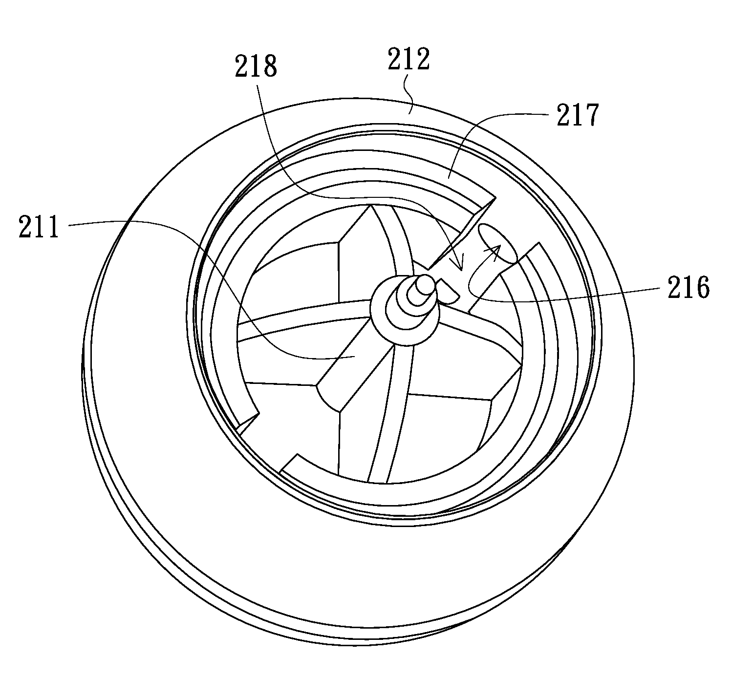
[0025] FIG. 4 is a three-dimensional view of a rotating shaft and an annular wrapping element according to an embodiment of the present invention; and
[0026] FIG. 5 is a schematic diagram showing a signal emitter which is mounted in the annular wrapping element according to an embodiment of the present invention.
DETAILED DESCRIPTION OF PREFERRED EMBODIMENTS
[0027] The present invention will now be described more specifically with reference to the following embodiments. It is to be noted that the following descriptions of preferred embodiments of this invention are presented herein for purpose of illustration and description only. It is not intended to be exhaustive or to be limited to the precise form disclosed.
[0028] FIG. 2 is a cross-sectional view of a wrist exercising device according to an embodiment of the present invention. FIG. 3 is an exploded, three-dimensional view of the wrist exercising device of FIG. 2. Referring to FIG. 2 and FIG. 3, the wrist exercising device 200 includes a housing 300 and a rotating device 210 disposed in the housing 300.
[0029] The housing 300 includes a first cover 310, a second cover 320 and a fixing ring 330. The first cover 310 can, without limitation, be made of metal (e.g., stainless steel) or plastic. The first cover 310 has a first opening end 311 and a first joining portion 312 extending outside from the first opening end 311. The first joining portion 312 extending outside from the first opening end 311. The first joining portion 312 includes a first annular bottom wall 313 extending outside from the first opening end 311 and a first annular side wall 314 surrounding the first annular bottom wall 313. In detail, the first cover 310 may further have a first bottom wall 315 opposite to the first opening end 311 and a first side wall 316 surrounding the first bottom wall 315. The first annular bottom wall 313 extends outside from the first side wall 316. An opening 317 is defined in the first bottom wall 315, although it is not necessary to define the opening 317 in the first bottom wall 315.
[0030] Similar to the first cover 310, the second cover 320 can, without limitation, be made of metal (e.g., stainless steel) or plastic. The second cover 320 has a second opening end 321 and a second joining portion 322 extending outside from the second opening end 321. The second joining portion 322 includes a second annular bottom wall 323 extending outside from the second opening end 321 and a second annular side wall 324 extending surrounding the second annular bottom wall 323. In detail, the second cover 320 may further have a second bottom wall 325 opposite to the second opening end 321 and a second side wall 326 surrounding the second bottom wall 325. The second annular bottom wall 323 extends outside from the second side wall 326. An opening 327 is defined in the second bottom wall 325, although it is not necessary to define the opening 327 in the second bottom wall 325.
[0031] The first joining portion 312 and the second joining portion 322 are capable of being joined with each other. In the illustrated embodiment, an outer diameter smaller of the first annular side wall 314 can be smaller than an outer diameter of the second annular side wall 324. When the first joining portion 312 and the second joining portion 322 are joined with each other, the first annular side wall 314 is located inside the second annular side wall 324. Furthermore, the outer diameter of the first annular side wall 314 may be about equal to an inner diameter of the second annular side wall 324, so that the first annular side wall 314 and the second annular side wall 324 can be joined with each other by interference fit. However, the manner to assemble the first annular side wall 314 with the second annular side wall 324 is not limited to the above. In another embodiment, the outer diameters of the first annular side wall 314 and the second annular side wall 324 can be identical.
[0032] The fixing ring 330 wraps the first joining portion 312 and the second joining portion 322 which are joined with each other. Specifically, an annular groove 334 is defined in an inner wall 332 of the fixing ring 330 for receiving the first joining portion 312 and the second joining portion 322 which are joined with each other. In other words, the joined first and second joining portions 312, 322 are retained in the annular groove 334. In the illustrated embodiment, the fixing ring 330 has elasticity and can be made of plastic, rubber, or other elastic materials. The fixing ring 330 can be integrally formed from a monolithic material. In another embodiment, the fixing ring 330 can be formed by combining multiple elements. In another embodiment, the fixing ring 330 can have no elasticity.
[0033] The rotating device 210 includes a rotating shaft 211, an annular wrapping element 212 and a rotating ring 213. Two ends of the rotating shaft 211 are, for example, installed between the first annular bottom wall 313 and the second annular bottom wall 323, while the annular wrapping element 212 surrounds a portion of the rotating shaft 211. The rotating device 210, for example, is provided with a plurality of vanes 214. The rotating ring 213 surrounds the rotating shaft 211 and has two opposite shaft holes 213a. The two ends of the rotating shaft 211 are inserted into the two shaft holes 213a of the rotating ring 213, respectively. Additionally, the rotating shaft 211 and the annular wrapping element 212 can be integrated into one piece. The material for the rotating shaft 211 and the annular wrapping element 212 can, without limitation, be metal such as zinc alloy. In other embodiments, the rotating shaft 211 and the annular wrapping element 212 can be formed separately and then combined to each other.
[0034] The illustrated twist exercising device 200 can further include a first annular track 220 and a second annular track 230. The first annular track 220 is disposed at the first annular bottom wall 313, the second annular track 230 is disposed at the second annular bottom wall 323, and the two ends of the rotating shaft 211 are disposed between the first annular track 220 and the second annular track 230. Specifically, the two ends of the rotating shaft 211 are leant on the first annular track 220 and the second annular track 230. The first annular track 220 and the second annular track 230 are made from such a material as to enable the first and second annular tracks 220, 230 to have a sufficient friction coefficient relative to the rotating shaft 211, so that the rotating shaft 211 can rotate relative to the first and second annular tracks 220, 230. For example, the first and second annular tracks 220, 230 can, without limitation, be made of plastic or rubber.
[0035] In another embodiment, when the first and second covers 310, 320 are made from such a material as to enable the first and second annular bottom walls 313, 323 to have a sufficient friction coefficient relative to the two ends of the rotating shaft 211 so that the rotating shaft 211 can rotate, the two ends of the rotating shaft 211 can be directly leant on the first and second annular bottom walls 313, 323. Therefore, the first and second annular tracks 220, 230 can be omitted. For example, when the first and second covers 310, 320 are made of plastic, the two ends of the rotating shaft 211 can be directly leant on the first and second annular bottom walls 313, 323.
[0036] In the illustrated twist exercising device 200, the first and second joining portions 312, 322 extend outside from the first and second covers 310, 320 of the housing 300, respectively. After the first and second joining portions 312, 322 are joined with each other, the joined first and second joining portions 312, 322 can as a whole be served as a holding part for the user to hold the twist exercising device 200, thereby reducing the risk of the twist exercising device 200 falling off from the palm of the user. Furthermore, since threads are not required to be formed on the first and second covers 310, 320, a thickness of each of the first and second covers 310, 320 can be significantly reduced, thereby reducing the material cost and the weight of the housing 300. Thus, the illustrated twist exercising device 200 has the advantages of low cost and light weight.
[0037] In order to render the user to know the number of revolutions of the rotating device 210 in the housing 300, the twist exercising device 200 can further include a counter 240. The counter 240 is, for example, disposed at one side of the second cover 320 opposite to the second opening end 321. That is, the counter 240 is disposed at the second bottom wall 325 of the second cover 320. In the embodiment wherein the second bottom wall 325 is defined with the opening 327, the counter 240 can be disposed in the opening 327. In another embodiment, the counter 240 is, for example, disposed at one side of the first cover 310 opposite to the first opening end 311. That is, the counter 240 is disposed at the first bottom wall 315 of the first cover 310. In the embodiment wherein the first bottom wall 315 is defined with the opening 317, the counter 240 can be disposed in the opening 317.
[0038] Except for the counter 240, the rotating device 210 further includes a signal emitter 215, wherein the signal emitter 215 is attached to the annular wrapping element 212 and configured to provide signals to the counter 240. When the rotating device 210 rotates, the signal emitter 215 rotates with the rotating device 210, and the counter 240 counts the number of resolutions of the rotating device 210 according to the variation of the sensed signal. In the illustrated embodiment, the signal emitter 215 is, for example, a magnet unit, and the counter 240 is capable of sensing magnetic signals. The magnet unit includes, for example, a fixing tube 251 and a magnet 252 disposed in the fixing tube 251.
[0039] FIG. 4 is a three-dimensional view of the rotating shaft and the annular wrapping element according to an embodiment of the present invention. FIG. 5 is a schematic diagram showing the signal emitter which is mounted in the annular wrapping element according to an embodiment of the present invention. Referring to FIG. 3 to FIG. 5, the annular wrapping element 212 is, for example, defined with a mounting hole 216. The rotating shaft, for example, has an annular inner wall 217. The annular inner wall 217 is defined with a notch 218. The notch 218 is communicated with the mounting hole 216 so that the mounting hole 216 is exposed. The notch 218 is provided with at least an abutting portion 219, wherein two abutting portions 218 are provided in the notch 218 in the illustrated embodiment. However, the number of the abutting portion 219 is not limited in the present invention. The fixing tube 251 of the signal emitter 215 is disposed into the mounting hole 216 via the notch 218 under the direction E shown in FIG. 5. The fixing tube 251 is, for example, provided with at least an elastic pillar protruding out of the mounting hole 216. Each elastic pillar 253 corresponds to and abuts against one abutting portion 219, so that the fixing tube 251 is avoided from dropping off from the mounting hole 216. Furthermore, the mounting hole 216 is, for example, a through hole in the illustrated embodiment. In order to prevent the fixing tube 251 from dropping outside the annular wrapping element 212 from the mounting hole 216, the fixing tube 251 can further be provided with at least a stopping block 254 protruding out of the mounting hole 216, wherein two opposite stopping blocks 254 are provided on the fixing tube 251 in FIG. 3 as an example. Each stopping block 254 interferes with the annular wrapping element 212 and thus cannot be inserted into the mounting hole 216, thereby preventing the fixing tube 251 from dropping outside the annular wrapping element 212 from the mounting hole 216.
[0040] It should be pointed out that the stopping block 254 is not a necessary part of the fixing tube 251. In another embodiment, the diameter of the mounting hole 216 can be gradually reduced from an inner side to an outer side of the annular wrapping element 212 to cause the diameter of the mounting hole 216 at the outer side of the annular wrapping element 212 to be smaller than a diameter of the fixing tube 251, thereby preventing the fixing tube 251 from dropping outside the annular wrapping element 212 from the mounting hole 216. In another embodiment, an inner surface of the mounting hole 216 can be provided with an abutting portion. Due to the abutting portion, the fixing tube 251 is prevented from dropping outside the annular wrapping element 212 from the mounting hole 216. In yet another embodiment, the mounting hole 216 is a blind hole to accordingly prevent the fixing tube 251 from dropping outside the annular wrapping element 212 from the mounting hole 216.
[0041] While the invention has been described in terms of what is presently considered to be the most practical and preferred embodiments, it is to be understood that the invention needs not be limited to the disclosed embodiment. On the contrary, it is intended to cover various modifications and similar arrangements included within the spirit and scope of the appended claims which are to be accorded with the broadest interpretation so as to encompass all such modifications and similar structures.
* * * * *
D00000
D00001
D00002
D00003
XML
uspto.report is an independent third-party trademark research tool that is not affiliated, endorsed, or sponsored by the United States Patent and Trademark Office (USPTO) or any other governmental organization. The information provided by uspto.report is based on publicly available data at the time of writing and is intended for informational purposes only.
While we strive to provide accurate and up-to-date information, we do not guarantee the accuracy, completeness, reliability, or suitability of the information displayed on this site. The use of this site is at your own risk. Any reliance you place on such information is therefore strictly at your own risk.
All official trademark data, including owner information, should be verified by visiting the official USPTO website at www.uspto.gov. This site is not intended to replace professional legal advice and should not be used as a substitute for consulting with a legal professional who is knowledgeable about trademark law.