Method and Device for Monitoring Backbone Inter Base-Station Communication
Wegmann; Bernhard ; et al.
U.S. patent application number 13/518003 was filed with the patent office on 2012-12-27 for method and device for monitoring backbone inter base-station communication. Invention is credited to Bernhard Wegmann, Wolfgang Zirwas.
| Application Number | 20120329401 13/518003 |
| Document ID | / |
| Family ID | 41693187 |
| Filed Date | 2012-12-27 |


| United States Patent Application | 20120329401 |
| Kind Code | A1 |
| Wegmann; Bernhard ; et al. | December 27, 2012 |
Method and Device for Monitoring Backbone Inter Base-Station Communication
Abstract
A method and a device for data processing in a network are provided, wherein a base station determines a performance of a connection to at least one other base station. Furthermore, a communication system is suggested comprising said device.
| Inventors: | Wegmann; Bernhard; (Holzkirchen, DE) ; Zirwas; Wolfgang; (Munchen, DE) |
| Family ID: | 41693187 |
| Appl. No.: | 13/518003 |
| Filed: | December 22, 2009 |
| PCT Filed: | December 22, 2009 |
| PCT NO: | PCT/EP2009/067790 |
| 371 Date: | August 14, 2012 |
| Current U.S. Class: | 455/67.11 |
| Current CPC Class: | H04L 43/0882 20130101; H04L 43/0894 20130101; H04L 43/08 20130101; H04W 24/06 20130101; H04L 41/0803 20130101; H04L 43/0811 20130101; H04L 43/0852 20130101; H04W 92/20 20130101; H04L 43/10 20130101 |
| Class at Publication: | 455/67.11 |
| International Class: | H04W 24/00 20090101 H04W024/00 |
Claims
1. A method for processing data in a network, wherein a base station determines a performance of a connection to at least one other base station.
2. The method according to claim 1, wherein the performance is determined based on at least one of the following: a connectivity; a delay; a transmission capacity, in particular a data rate; a cost per data unit; a link usage; a configuration of a backbone network.
3. The method according to claim 1, wherein the performance of the connection between the base stations is determined by at least one measurement.
4. The method according to claim 3, wherein said at least one measurement comprises at least one of the following: a ping measurement; conveying an increasing amount of traffic via the connection between the base stations until an error occurs.
5. The method according to claim 1, wherein the base station and the at least one other base station are connected via an X2 interface.
6. The method according to claim 1, wherein based on the performance, a decentralized or a centralized coordinated multipoint transmission is activated.
7. The method according to claim 1, wherein performances of connections between base stations of a coordinated multipoint area are determined.
8. The method according to claim 1, wherein the performance is conveyed to a centralized network component.
9. The method according to claim 8, wherein the centralized network component selects a base station to become a central unit of a coordinated multipoint area.
10. The method according to claim 8, wherein the centralized network component conveys a message to at least one base station, wherein said message comprises at least one of the following functions: the message initiates the base station to determine the performance of at least one connection to at least one other base station; the message requests performance results that have been determined; the message informs the base station about parameters or performance limitations.
11. The method according to claim 1, wherein the performance of the connection between base stations is determined repeatedly, in particular iteratively or on a substantially regular basis.
12. A device for data processing in a network comprising or being associated with a processing unit that is arranged to execute the following step: a performance of a connection between at least two base stations of the network is determined.
13. The device according to claim 12, wherein said device is associated with at least one centralized network component or at least one base station.
14. The device according to claim 12, wherein the base stations are connected via an X2 interface.
15. A communication system comprising the device according to claim 12.
Description
[0001] The invention relates to a method and to a device for data processing in a network. Further, a communication system is suggested comprising at least one such device.
[0002] For LTE Advanced (LTE-A), a so-called coordinated multi point (CoMP) transmission is a study item with the goal to overcome inter cell interference limitations. High performance gains can be expected from joint precoding solutions, where precoded data are simultaneously transmitted from several base stations (eNBs) to several mobile terminals (UEs).
[0003] CoMP transmission refers to a coherent multi-cell transmission with several data streams being jointly transmitted over the same radio resources. Since channel state information of all such jointly used links is known and exploited by means of precoding, each link can be decoded in an interference-free manner. Determining the cooperation area and/or choosing a base station (e.g., eNB) that has (or is provided with) functionalities of a central unit (CU) is regarded as an issue of a self-organizing network (SON).
[0004] An X2 interface (see 3GPP TS36.300 V9.1.0) was introduced to realize logical connections between base stations in a meshed manner. Currently, the X2 interface is basically used to exchange signaling information across several cells, e.g., handover or SON messaging.
[0005] Utilizing CoMP transmission, also user data has to be transmitted over the X2 interface. Therefore, the X2 transmission capability becomes of significant importance.
[0006] However, it is a disadvantage that using existing X2 interfaces for conveying CoMP transmission traffic may experience a significant delay and therefore CoMP transmission may not provide the expected benefit.
[0007] The problem to be solved is to overcome the disadvantage stated above and in particular to provide an efficient utilization of the X2 interface for CoMP transmission purposes.
[0008] This problem is solved according to the features of the independent claims. Further embodiments result from the depending claims.
[0009] In order to overcome this problem, a method for processing data in a network is provided, wherein a base station determines a performance of a connection to at least one other base station.
[0010] Said network may comprise a wireless network, e.g. 2G, 2.5G, 3G, LTE, LTE-A or any other (upcoming) network.
[0011] The connection between the base stations also comprises an interface towards another base station. In other words, instead of the performance of the connection between the base stations, it could be referred to a performance of the interface between two base stations. Each base station may be connected to several other base stations. Each such connection may be evaluated regarding its performance. The type of interface between two base stations may be an X2 interface.
[0012] This approach efficiently determines the actual performance of the connection between base stations; based on such performance, the decision can be made whether to initialize centralized or decentralized CoMP transmission or to conduct no CoMP transmission at all. In addition, when the decision is made to enable centralized CoMP transmission, based on the performance obtained, a central network component can determine which base station is a suitable candidate to become a central unit (CU) of a CoMP area. In particular, a SON algorithm may determine the best candidate for a CU among the base stations, e.g., of a CoMP area.
[0013] In an embodiment, the performance is determined based on at least one of the following: [0014] a connectivity; [0015] a delay; [0016] a transmission capacity, in particular a data rate; [0017] a cost per data unit; [0018] a link usage; [0019] a configuration of a backbone network.
[0020] Advantageously, all parameters that may have an impact on the connection could be determined. It is noted that current, minimum, maximum, average values and variances could be determined, in particular measured or monitored (e.g., measured on a more or less regular basis).
[0021] In another embodiment, the performance of the connection between the base stations is determined by at least one measurement.
[0022] In a further embodiment, said at least one measurement comprises at least one of the following: [0023] a ping measurement; [0024] conveying an increasing amount of traffic via the connection between the base stations until an error occurs.
[0025] Said error may be a delay exceeding a predefined threshold or it may be an explicit error. This error indicates an upper threshold of the data rate to be conveyed (in addition to already existing user traffic) over this particular connection.
[0026] The measurements may be triggered and/or coordinated by a centralized network component (e.g., a SON entity). This advantageously avoids any misinterpretation of the measurements.
[0027] In a next embodiment, the base station and the at least one other base station are connected via an X2 interface.
[0028] It is also an embodiment that based on the performance, a decentralized or a centralized coordinated multipoint transmission is activated.
[0029] It is noted that the performance of the X2 interface may be used (e.g., by a centralized network component, in particular a SON entity) to determine whether decentralized self-organizing cooperation (DCO) should be preferred over centralized CoMP. This will be the case if the performance of the X2 interface(s) within a potential CoMP area does not suffice. In this case, centralized CoMP is not feasible and the more complex DCO approach may have to be pursued.
[0030] However, advantageously, based on the measurement of the performance of the interface between the base stations it is possible (e.g. for a centralized network component) to decide whether or not centralized CoMP transmission is feasible. This efficiently avoids starting CoMP processing without any chance to achieve the expected benefit.
[0031] Pursuant to another embodiment, performances of connections between base stations of a coordinated multipoint area are determined.
[0032] According to an embodiment, the performance is conveyed to a centralized network component.
[0033] According to another embodiment, the centralized network component selects a base station to become a central unit of a coordinated multipoint area.
[0034] This is in particular done in case the centralized CoMP approach appears to be feasible due to the performance of the interfaces between the base stations. For this purpose, a predefined threshold could be provided that must not be reached; otherwise, decentralized CoMP transmission may be performed (DCO) or no CoMP transmission may be performed at all. In addition, the measurements may indicate the best location of the central unit of the cooperation area.
[0035] In yet another embodiment, the centralized network component conveys a message to at least one base station, wherein said message comprises at least one of the following functions: [0036] the message initiates the base station to determine the performance of at least one connection to at least one other base station; [0037] the message requests performance results that have been determined; [0038] the message informs the base station about parameters or performance limitations.
[0039] The parameters may comprise cost per data unit. Furthermore, performance limitations may be directed to using inband backbone relaying for user data traffic transfer or proposing enhancements for certain X2 links, which have been determined to be bottlenecks.
[0040] According to a next embodiment, the performance of the connection between base stations is determined repeatedly, in particular iteratively or on a substantially regular basis.
[0041] The performance may have to be updated in order to become aware of fluctuations, e.g., due to network growth, etc.
[0042] The problem stated above is also solved by a device for data processing in a network, comprising or being associated with a processing unit that is arranged to execute the following step: a performance of a connection between at least two base stations of the network is determined.
[0043] It is noted that the steps of the method stated herein may be executable on this processing unit as well.
[0044] According to an embodiment, the device is associated with at least one centralized network component or at least one base station.
[0045] The centralized network component may be a radio resource manager according to LTE.
[0046] Pursuant to yet an embodiment, the base stations are connected via an X2 interface.
[0047] In particular, a set of base stations can be grouped as a CoMP area (also referred to as cooperation area). For CoMP transmission purposes, coordinated multipoint transmission (precoding) is conducted for the set of base stations grouped together in the CoMP area.
[0048] It is further noted that said processing unit can comprise at least one, in particular several means that are arranged to execute the steps of the method described herein. The means may be logically or physically separated; in particular several logically separate means could be combined in at least one physical unit.
[0049] Said processing unit may comprise at least one of the following: a processor, a microcontroller, a hard-wired circuit, an ASIC, an FPGA, a logic device.
[0050] The solution provided herein further comprises a computer program product directly loadable into a memory of a digital computer, comprising software code portions for performing the steps of the method as described herein.
[0051] In addition, the problem stated above is solved by a computer-readable medium, e.g., storage of any kind, having computer-executable instructions adapted to cause a computer system to perform the method as described herein.
[0052] Furthermore, the problem stated above is solved by a communication system comprising at least one device as described herein.
[0053] Embodiments of the invention are shown and illustrated in the following figures:
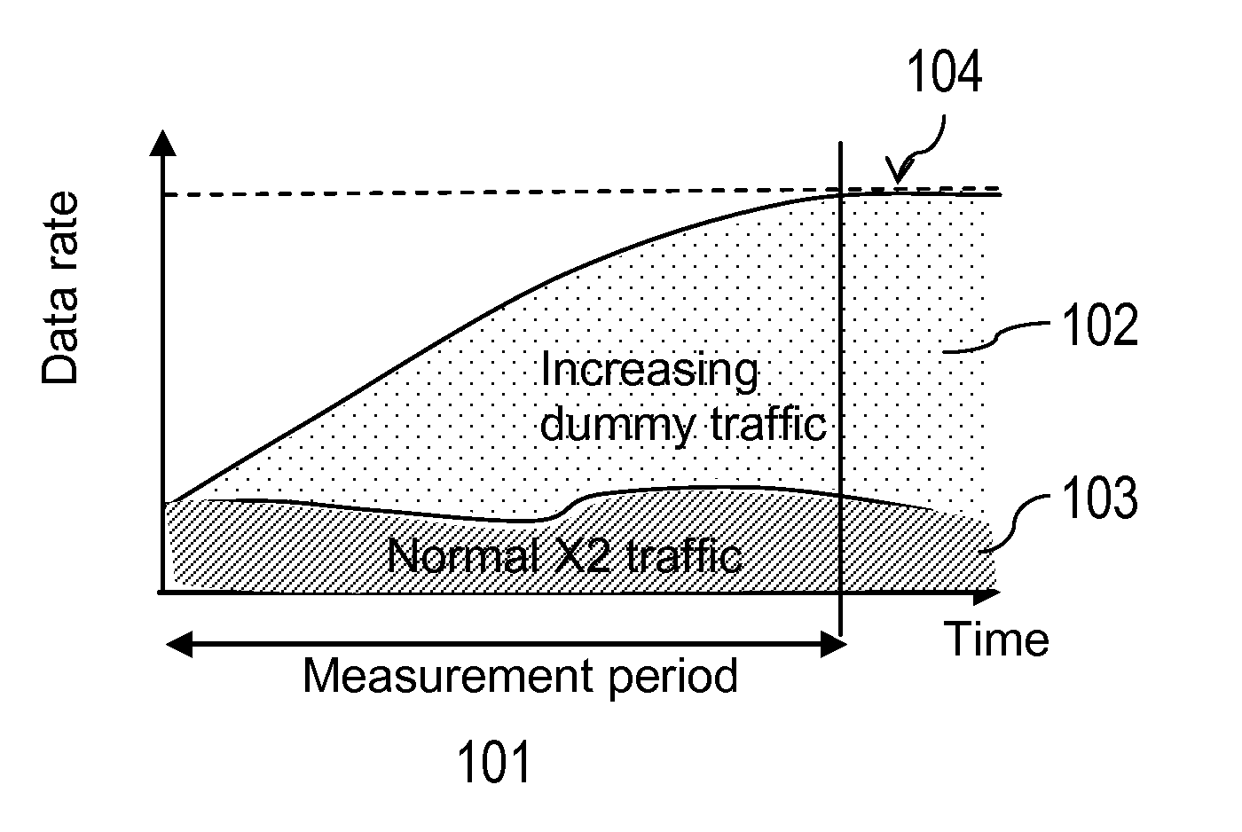
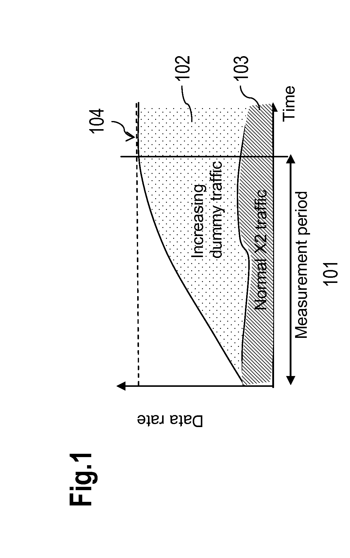
[0054] FIG. 1 shows a schematic diagram with a data rate denoted in view of a time axis that is used to visualize a measurement of the performance of an X2 interface;
[0055] FIG. 2 shows a schematic block diagram comprising a centralized network element and several base stations (eNBs), wherein the eNBs are connected via X2 interfaces;
[0056] FIG. 3 shows an exemplary message diagram between eNBs and the centralized network element shown in FIG. 2 as well as an OAM unit.
[0057] A CoMP area may comprise several eNBs, wherein one eNB could be selected as a central unit to control procedures of this CoMP area. In order for the SON to determine a suitable candidate for the CU of a CoMP area, information regarding characteristics (e.g., connectivity, capability) of the X2 interfaces between the eNBs of the CoMP area is required.
[0058] Such Information regarding the characteristics of the X2 interface may, e.g., comprise: [0059] a delay of each X2 interface; [0060] a maximum transmission capacity (data rate) across each X2 interface; [0061] cost per megabyte (for each X2 interface); [0062] a statistic of the link usage (first and second order moments) for each X2 interface.
[0063] The delay is a critical issue, because channel state information (CSI) and pre-coded user data must not become outdated, otherwise CoMP transmission would not be able to provide the expected benefit.
[0064] Accordingly, the SON entity may choose those eNBs with links of low delay, e.g., in the range of few milliseconds only in order to enable an efficient and powerful precoding. Also, different eNBs may assume the CU role depending on CoMP set configurations. Hence, an eNB may be selected as CU that provides the fastest X2 interface connections to the other eNBs of the CoMP area.
[0065] The SON entity may also have to decide to enable decentralized self-organizing cooperation (DCO) instead of the centralized scheme in case the performance of the X2 interface(s) do(es) not suffice. DCO provides the same precoding at each eNB in parallel so that each eNB can (autonomously) calculate its transmission signals. In such case, the user data signals to be jointly transmitted are multi-casted by the backbone via S1 interfaces to the corresponding eNBs of the CoMP area and the CSI of all radio links is multi-casted by the UEs in uplink direction to all eNBs involved. Because of the challenging synchronization regarding precoding, processing and scheduling for all eNBs, it is an objective to limit DCO to those scenarios when central processing is not feasible.
[0066] In a similar manner the other criteria may be taken into account by the SON algorithms in order to determine which eNB to select as CU of a CoMP area.
[0067] The approach provided suggests determining a performance of at least one X2 interface and based on such performance the SON may decide whether to initiate DCO or central processing, e.g., via a CU of a CoMP area.
[0068] Advantageously, said performance may be any X2 interface capability, which may be determined, e.g., based on measurements.
[0069] Further, it is suggested that performance data regarding the X2 interface is provisioned, in particular regarding the X2 interface's transmission capability. Measurements may be utilized, e.g., to update this performance data.
[0070] The required attributes determining the X2 transmission capability can be either configured when setting up the transport bearer of the corresponding X2 interface and remain fixed or they may be updated by measurements, e.g., on a regular basis. For instance, ping measurements may be used to determine a delay over the X2 interface.
[0071] X2 interfaces may be connected via a layer 3 VPN (virtual private network) service over a broadband metro network with several routers in between. Changes of the MAN or WAN may affect the delay and the performance of the X2 interface may thus have to be (dynamically) updated. In addition, traffic load of eNBs connected may also have an impact on the time delay of the X2 interface.
[0072] A maximum data rate can be determined by transmitting dummy data with an increasing data rate for a short predefined measurement time and in a predefined manner (e.g. increasing with a constant rate until an overflow is detected). Such measurements can be done in a coordinated way to avoid simultaneous measurements of different cells that might influence each other. Therefore, the measurements can be triggered by SON messages for each cell. This may ensure that measurements do not occur during high or full load situations; instead, the measurements can be conducted during low traffic time, e.g., at night, with only a minor impact on the overall system performance.
[0073] Hence, this solution also relates to measurement procedures for evaluating CoMP transmission relevant X2 link performance parameters between a set of eNBs. These measurements can be conducted for already established GTP tunnels as being used for user data traffic transfer between cooperating eNBs.
[0074] It is noted that worst case delays as defined for the X2 interface delay (20 ms) or peak user data rates for a given link (e.g., 1 Gbit/s for gigabit Ethernet) are not sufficient for the purpose of this approach. Instead, the actual data rate achievable over the physical link established is required including the link's routers and switches etc.
[0075] Measurements may comprise at least one of the following:
[0076] a) A delay: a minimum delay, a maximum delay, a mean delay, a variance of the delay, etc. For example, IP ping round trip time (RTT) measurements can be used to determine the delay.
[0077] b) A user data traffic capacity: minimum, maximum, mean/average value, variance, etc. of such user data traffic can be measured (or monitored).
[0078] c) A configuration of the backbone network can be determined, e.g., a number of links, a setup of switches and routers, currently used traffic priorities, various modes (e.g., gold, silver, bronze) of switches for guaranteeing certain delay limits up to predetermined data rates etc.
[0079] For an optimized or improved utilization of the backhaul network, other parameters, e.g., cost per megabyte, could be of interest. Such parameter could be supplied by the MNO for each link and it may be stored with the eNBs.
[0080] If not provided, a default value could be assumed. The parameter cost could be considered in different ways, e.g., directly as cost per bit or indirectly as priority levels or specific cost classes. Such priority levels--provided by the MNO--may reflect other motivations of the MNO as to why a particular link shall be preferred over another link (e.g., due to power consumption issues). Hence, the preferences of the MNO could be reflected accordingly.
[0081] In addition to the measurements, SON messages may be required to
[0082] 1) trigger the above-mentioned measurement procedures;
[0083] 2) request (already stored) measurement results from at least one eNB;
[0084] 3) inform higher layers of the network or OAM about performance limitations in certain areas of the network and potential alternatives, e.g., using inband backbone relaying for user data traffic transfer or proposing enhancements for certain X2 links, which have been determined to be serious bottlenecks.
[0085] FIG. 1 shows a schematic diagram with a data rate denoted in view of a time axis that is used to visualize a measurement of the performance of an X2 interface.
[0086] A normal traffic 103 is conveyed over the X2 interface. During a measurement period 101, dummy traffic 102 can be gradually increased by an eNB in order to determine a threshold 104 indicating the maximum data rate that can be conveyed via the X2 interface for a certain delay limit. Several such measurements may be conducted and a mean value of those several measurements can be determined by the eNB. The eNB may thus become aware of the amount of traffic that could be conveyed via the X2 interface.
[0087] FIG. 2 shows a schematic block diagram comprising a centralized network element 201 and several base stations (eNBs) 202 to 204, wherein the eNBs are connected via X2 interfaces 205 to 207. The centralized network element 201 is connected to each of the eNBs 202 to 204 via connections 208 to 210. The centralized network element 201 could be a radio resource manager (RRM) of an LTE network.
[0088] FIG. 3 shows an exemplary message diagram between the eNBs 202, 203 and the centralized network element 201 shown in FIG. 2 and an OAM unit 301.
[0089] By conveying a message 302 to the eNB 202, the centralized network element 201 triggers this eNB 202 to conduct measurements regarding its X2 interfaces. The performance of the X2 interface between the eNB 202 and the eNB 203 is determined by sending a (dummy) packet 303 toward the eNB 203 and waiting for an acknowledgment 304. The delay between the messages 303 and 304 can be measured by the eNB 202 and conveyed via a message 306 towards the centralized network element 201. Preferably, several such measurements are conducted (for each X2 interface) to determine an average value of the performance of the X2 interface between the eNB 202 and the eNB 203.
[0090] Accordingly, the centralized network element 201 may convey a message 307 towards the eNB 203 requesting to conduct measurements of the performance of its X2 interfaces. The eNB 203 may convey (e.g., increasing) traffic 308 towards the eNB 202 and monitor a delay of feedback provided by said eNB 202. If the delay exceeds a predefined threshold or in case packets are not acknowledged (indicated by arrow 309), the eNB 203 may assume a maximum data rate that could be conveyed across its X2 interface towards the eNB 202. This measurement may be conducted iteratively in order to determine an average value for such maximum data rate or performance of the X2 interface. The result of the measurement(s) could be conveyed via a message 310 to the centralized network element 201.
[0091] Furthermore, a message 311 may be conveyed from the OAM unit 301 to the eNB 202 and a message 312 may be conveyed from the OAM unit 301 to the eNB 203, wherein these messages may convey cost per bit supplied by an operator. This cost per bit could be considered by the performance determined for the X2 interfaces and conveyed to the centralized network element 201.
[0092] Based on the information provided, the centralized network element 201 may utilize CoMP areas or it may decide whether CoMP is processed in a centralized or in a DCO manner.
[0093] It is noted that the block structure shown in FIG. 2 and FIG. 3 could be implemented by a person skilled in the art as various physical units, wherein the eNBs or the centralized network element could be realized as at least one logical entity that may be deployed as program code, e.g., software and/or firmware, running on a processing unit, e.g., a computer, microcontroller, ASIC, FPGA and/or any other logic device.
[0094] The functionality described herein may be based on an existing component of a (wireless) network, which is extended by means of software and/or hardware. The eNB mentioned herein could also be referred to as any base station pursuant to any communication standard.
[0095] The eNB, the base station or the centralized network element may each comprise at least one physical or logical processing unit that is arranged for determining a performance of a convection or interface between at least two base stations.
LIST OF ABBREVIATIONS
[0096] BS Base Station [0097] CoMP Coordinated Multipoint [0098] CSI Channel State Information [0099] CU Central Unit [0100] DCO Decentralized Self Organizing Cooperation [0101] eNB evolved Node B [0102] GPRS General Packet Radio Service [0103] GTP GPRS Tunneling Protocol [0104] ID Identification/Identifier [0105] IP Internet Protocol [0106] JP Joint Processing [0107] LTE Long Term Evolution [0108] LTE-A LTE--Advanced [0109] MAN Metropolitan Area Network [0110] MNO Mobile Network Operator [0111] MS Mobile Station [0112] NB Node B [0113] OAM Operation and Maintenance [0114] RTT Round Trip Time [0115] SON Self Optimizing Network [0116] SON Self Optimizing Network [0117] UE User Equipment [0118] VPN Virtual Private Network [0119] WAN Wide Area Network
* * * * *
D00000
D00001
D00002
D00003
XML
uspto.report is an independent third-party trademark research tool that is not affiliated, endorsed, or sponsored by the United States Patent and Trademark Office (USPTO) or any other governmental organization. The information provided by uspto.report is based on publicly available data at the time of writing and is intended for informational purposes only.
While we strive to provide accurate and up-to-date information, we do not guarantee the accuracy, completeness, reliability, or suitability of the information displayed on this site. The use of this site is at your own risk. Any reliance you place on such information is therefore strictly at your own risk.
All official trademark data, including owner information, should be verified by visiting the official USPTO website at www.uspto.gov. This site is not intended to replace professional legal advice and should not be used as a substitute for consulting with a legal professional who is knowledgeable about trademark law.