Wave-powered autonomous plankton collector
Duke; John Hincks
U.S. patent application number 13/534644 was filed with the patent office on 2012-12-27 for wave-powered autonomous plankton collector. Invention is credited to John Hincks Duke.
| Application Number | 20120329345 13/534644 |
| Document ID | / |
| Family ID | 47362285 |
| Filed Date | 2012-12-27 |


| United States Patent Application | 20120329345 |
| Kind Code | A1 |
| Duke; John Hincks | December 27, 2012 |
Wave-powered autonomous plankton collector
Abstract
An autonomous submersible vessel employs ambient wave energy to both propel itself and to generate required onboard electrical power. The vessel combines a ballast stabilized stator portion and a wave orbit driven rotor portion. Controlled resistance to their relative rotation occurs only when the horizontal component of wave orbit motion coincides with the desired direction of navigation, so increased hydrodynamic drag at that time acts to pull the vessel forward. The vessel incorporates a means to collect and preserve plankton samples. The vessel design enables alternate operation as an oceanographic glider to also navigate in deep water and in calm seas.
| Inventors: | Duke; John Hincks; (Providence, RI) |
| Family ID: | 47362285 |
| Appl. No.: | 13/534644 |
| Filed: | June 27, 2012 |
Related U.S. Patent Documents
| Application Number | Filing Date | Patent Number | ||
|---|---|---|---|---|
| 61501735 | Jun 27, 2011 | |||
| Current U.S. Class: | 440/9 ; 114/256; 114/331; 290/53 |
| Current CPC Class: | Y02E 10/30 20130101; F05B 2250/44 20200801; B63B 2211/02 20130101; B63G 2008/002 20130101; B63G 8/001 20130101; B63H 19/02 20130101; B63G 8/08 20130101; F03B 13/20 20130101; B63J 3/04 20130101; B63G 2008/004 20130101; Y02T 70/5236 20130101 |
| Class at Publication: | 440/9 ; 114/331; 114/256; 290/53 |
| International Class: | B63H 19/04 20060101 B63H019/04; B63B 25/00 20060101 B63B025/00; F03B 13/20 20060101 F03B013/20; B63G 8/14 20060101 B63G008/14 |
Claims
1. A vessel that incorporates a ballast stabilized stator portion, a wave orbit driven rotor portion, a means to generate electrical energy from the relative rotation of said rotor portion about said stator portion, and a control means that activates said electrical power generation during power phases when the horizontal component of wave orbit motion is in a desired direction of navigation.
2. The vessel of claim 1 in which said rotor portion incorporates one or more planar wing surfaces that are substantially radial to the axis of rotation of the rotor portion, and the centroids of said surfaces are offset from that axis of rotation.
3. The vessel of claim 2 in which the angle between said planar wing surfaces and the instantaneous wave orbit direction is between ten and seventy degrees during said power phases.
4. The vessel of claim 2 in which the angle between said planar wing surfaces and the instantaneous wave orbit direction is substantially zero degrees between said power phases.
5. The vessel of claim 1 in which said rotor portion incorporates one or more permanent magnets and said stator portion incorporates one or more electrical coils.
6. The vessel of claim 1 containing a plankton collection and preservation means with injectable sealed compartments that are under partial vacuum prior to plankton collection.
7. The vessel of claim 1 in which active buoyancy control enables combined operation as an oceanographic glider.
8. A method of vessel propulsion by active modification of hydrodynamic drag in concert with instantaneous variation in wave orbit direction, where the dynamic reaction to said hydrodynamic drag is further converted to useful energy to power other vessel functions.
9. The method of claim 8 in which said dynamic reaction powers a rotary electrical generator.
10. The method of claim 8 in which said dynamic reaction powers a linear electrical generator.
Description
[0001] This application claims benefit to
[0002] U.S. Provisional Patent Application No. 61/501,735 filed on Jun. 27, 2011
1. BACKGROUND OF THE INVENTION
[0003] Presently accelerating ocean acidification is a potential threat to calcareous plankton that are vital to Earth's carbon cycle. This risk is particularly acute in the Southern Ocean because it is a large natural carbon dioxide sink, and the saturation of calcium carbonate in sea water is at greater risk in colder water. A means to economically increase surveillance of Southern Ocean acidification effects is valuable, particularly in southern winter when natural biological utilization of dissolved carbon dioxide is lowest. In addition to measuring and recording temperature, salinity, acidity, transparency, and phosphorescence of Southern Ocean waters, it will be valuable to continually collect actual samples of plankton at different seasons, times of day, water depths, and locations to discern their physiological response over time to the chemical stress of increasing acidity.
[0004] Because the Southern Ocean is the world's most hostile marine environment, deployment of autonomous vessels for the above purpose is economically preferable to manned survey ships. Operation of autonomous vessels for long periods of time in remote locations requires a renewable energy source. Pickens, in U.S. Pat. No. 3,872,819, and Hine et al., in U.S. Pat. No. 8,043,133, describe a surface vessel tethered to a subsurface device that develops horizontal propulsion from wave induced vertical motion. However, this arrangement does not permit deep water collection and is at risk of damage from floating ice. Also, the later invention employs solar power for instrumentation and communication, which is not available at high latitudes during critical winter months.
[0005] Here I describe a vessel that can harness subsurface wave energy to provide both propulsion and electrical power for onboard systems. It contains an automated means to collect and preserve plankton. The vessel may alternatively operate at depth and in calm seas by the known means of oceanographic gliders.
2. DESCRIPTION OF THE FIGURES
[0006] FIG. 1: A perspective view,
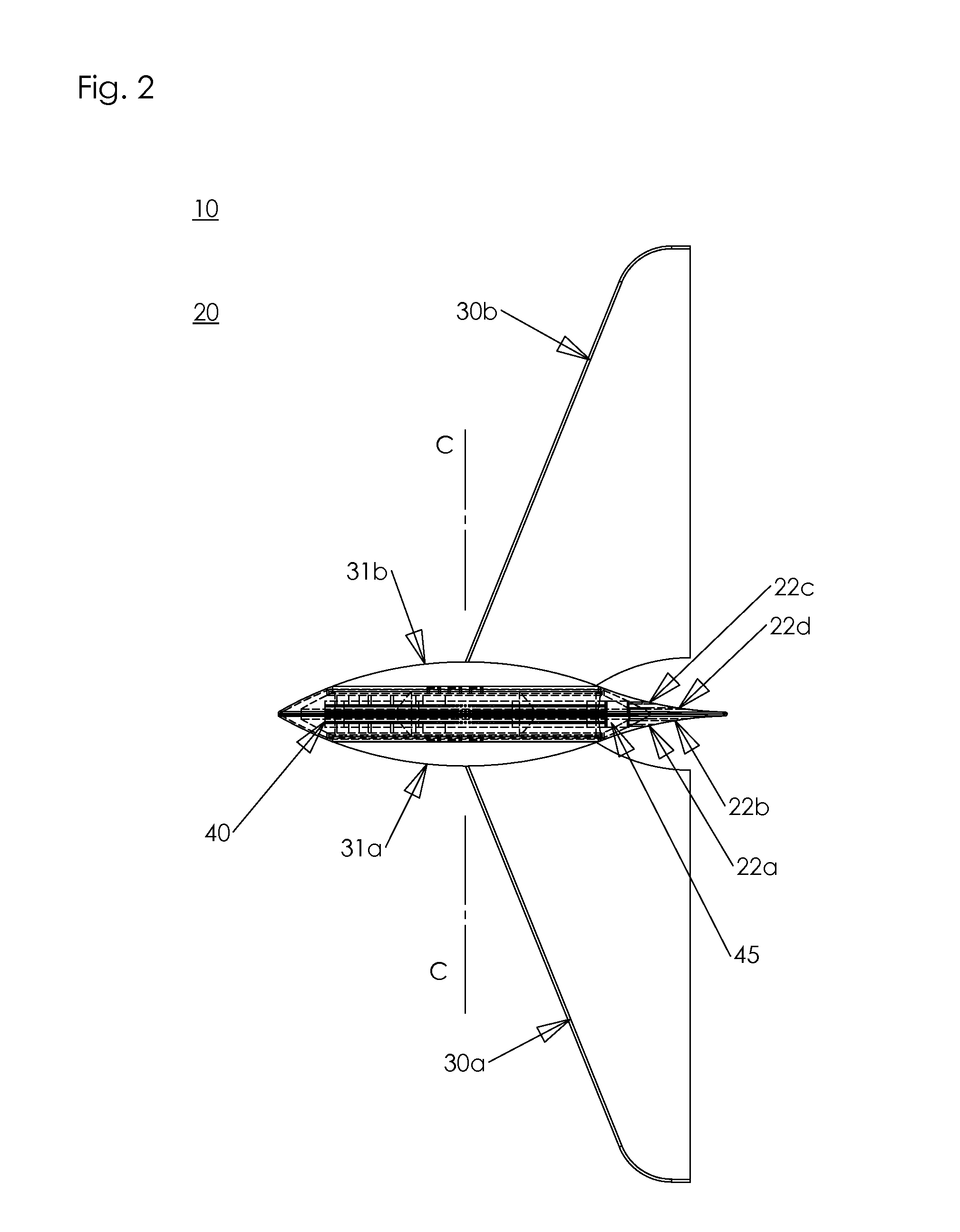
[0007] FIG. 2: A transparent downward view,
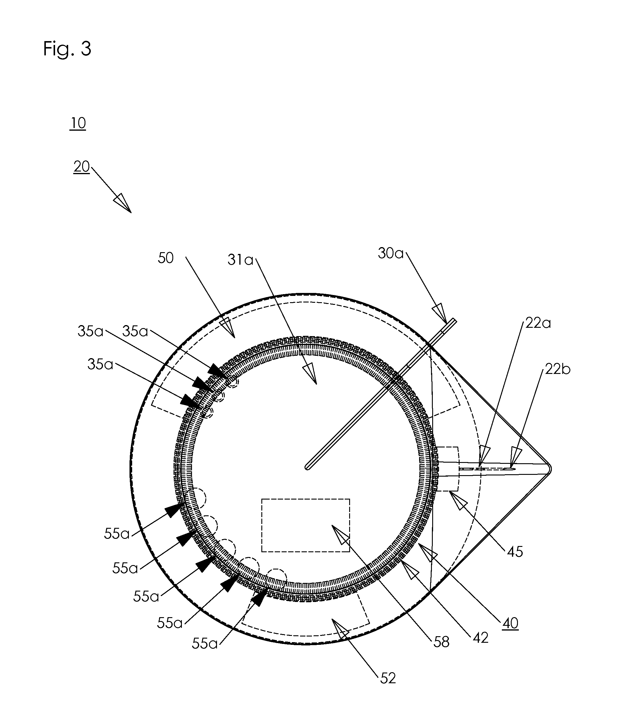
[0008] FIG. 3: A transparent sideward view,
[0009] FIG. 4: An exploded view, and
[0010] FIG. 5: A series of diagrams of wave orbit propulsion phases.
3. SPECIFICATION
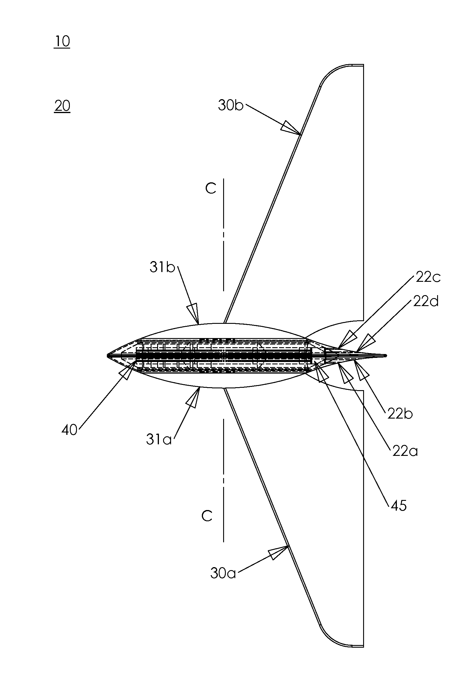
[0011] In FIG. 1, a volume of water 10 with surface waves propagating in a direction A envelops a vessel 20 being propelled in a direction B. Vessel 20 incorporates a forward portion and an aft portion that is oriented in service so the aft portion is in direction A of the forward portion. A set of plankton collection input ports 22a, 22b, 22c not shown, and 22d not shown communicate with the interior aft portion of vessel 20. A pair of wings 30a and 30b are independently rotatable about a central transverse axis C of vessel 20, and the planar surfaces of wings 30a and 30b are substantially radial to axis C. Wings 30a and 30b respectively incorporate a pair of hubs 31a and 31b not shown. The centroids of wings 30a and 30b are offset from axis C so that movement of water contacting wings 30a and 30b tends to rotate the longitudinal chord of wings 30a and 30b parallel to that water movement. Wings 30a and 30b and hubs 31a and 31b are substantially neutrally buoyant with respect to water 10.
[0012] FIG. 2 further shows the transverse location within vessel 20 of a rotatable sample collector 40 and a sample injector 45 that communicates with input ports 22a, 22b, 22c, and 22d. Injector 45 and/or the surface of vessel 20 may also incorporate known means not shown to measure and record the temperature, salinity, acidity, transparency, and phosphorescence of water 10.
[0013] FIG. 3 further shows a set of one or more permanent magnets 35a and 35b not shown that are respectively integral to a portion of the periphery of hubs 31a and 31b. A set of electrical coils 55a and 55b not shown are integral to a portion of the interior of vessel 20 substantially co-radial with magnets 35a and 35b. Magnets 35a and 35b are positioned to excite coils 55a and 55b when the horizontal component of water 10 wave orbit motion is in direction B, as described with reference to FIG. 5. A buoyancy compartment 50 is integral to the upper interior of vessel 20 and a ballast compartment 52 is integral to the lower interior of vessel 20. A control module 58 that provides known energy storage and buoyancy management means is also integral to the lower interior of vessel 20. Collector 40 incorporates a set of substantially radial compartments 42 that contain a known preserving solution under partial vacuum sealed by a known injectable elastometric material. Injector 45 incorporates known means to index compartments 42 by rotating collector 40 within the substantially co-radial central surfaces of injector 45, buoyancy compartment 50, and ballast compartment 52. Injector 45 further incorporates known means to sequentially concentrate and inject samples of plankton into compartments 42. In the preferred embodiment the number of compartments 42 is sufficient to collect a daytime and a nighttime sample for more than 365 days.
[0014] FIG. 4 shows the preferred construction arrangement in which vessel 20, buoyancy compartment 50, and ballast compartment 52 are separable about a vertical longitudinal plane.
[0015] FIG. 5 shows a series of eight wave orbit phase diagrams 100a, 100b, 100c, 100d, 100e, 100f, 100g, and 100h that indicate a sequence of directions of water particles in a wave propagating in direction A. This sequence is in 45 degree increments indicated numerically. A detail view adjacent to each phase diagram indicates the corresponding orientation of wings 30a and 30b.
[0016] In alternative embodiments the function of magnets 35a and 35b and coils 55a and 55b may be provided by known rotary positive displacement pump devices coupled to known electrical generating means.
4. OPERATION
[0017] In the preferred embodiment vessel 20 is both autonomous in service and remotely controllable through a known retractable and buoyant telecommunication antenna not shown.
[0018] The relative masses and arrangement of buoyancy compartment 50, ballast compartment 52, and control module 58 act to maintain level trim angle and heel angle of vessel 20. When stabilized in this way, the transverse span of wings 30a and 30b acts to maintain axis C approximately parallel to the prevailing wave front. Wave induced orbital changes in the direction of water 10 with respect to vessel 20 then act to rotate wings 30a and 30b and hubs 31a and 31b about axis C.
[0019] When magnets 35a and 35b excite coils 55a and 55b, magnetic resistance to the rotation of wing 30a and wing 30b both generates electrical power and increases the angle of attack of wing 30a and wing 30b, which periodically increases hydrodynamic drag in direction B to propel vessel 20 in direction B. With reference to FIG. 5, diagram 100a shows wave crest passage, when water particle motion is in direction A. Magnets 35a and 35b are in a no-load position at this time, so wings 30a and 30b freely weathervane in that direction. Magnets 35a and 35b remain in a no-load position for the subsequent 90 degrees of particle orbit rotation, equal to 1/4 wavelength of wave propagation, as shown in FIGS. 100b and 100c. Magnets 35a and 35b then excite coils 55a and 55b in a load phase for the subsequent 180 degrees of particle orbit, as shown in FIGS. 100d, 100e, 100f, and 100g. In the preferred embodiment the wing 30a and wing 30b angle of attack is 30 degrees in the position of FIG. 100d, and is 60 degrees in the positions of FIGS. 100e and 100f. During this rotary power generating interval the horizontal component of water particle motion is in direction B, so the resulting impulse force on wings 30a and 30b acts to propel vessel 20 in direction B. At the position of FIG. 100g, the horizontal component of water 10 motion in direction B then diminishes to zero, at which time magnets 35a and 35b rotate past coils 55a and 55b to a no-load position in which wings 30a and 30b weathervane again. This provides a means by which vessel 20 may hold position against prevailing wind drift currents, such as the Antarctic Circumpolar Current.
[0020] To steer vessel 20 in a given direction, control module 58 varies the electrical current in coils 55a and 55b to lessen load phase hydrodynamic drag on that side of vessel 20. By this means, control module 58 acts to turn axis C marginally out of parallel with the prevailing wave front. While FIG. 5 shows vessel 20 direction B in opposition to wave propagation direction A, vessel 20 may also reverse direction, in which case the load phase coincides with wave crest passage rather than wave trough passage. Vessel 20 may navigate perpendicular to wave propagation direction A by a zig-zag combination of direction reversal and sideward steering.
[0021] In the preferred embodiment control module 58 also incorporates known means to hold hubs 31a and 31b near position 100a and operate vessel 20 as an oceanographic glider. This enables deep water operation and calm sea navigation over limited distances.
[0022] The above means to steer and propel vessel 20 provides a capability to economically navigate.
[0023] Control module 58 further incorporates a means to compensate for changes in buoyancy resulting from plankton sample collection.
[0024] It will be understood that the principle of operation disclosed here may be embodied in other ways. For example, in one alternative embodiment, vessel 20 supports one or more one-way flap devices that open when instantaneous wave orbit direction aligns with the navigational objective. In such a case the power take-off may utilize the opening or linear translation of such flap devices.
* * * * *
D00000
D00001
D00002
D00003
D00004
D00005
XML
uspto.report is an independent third-party trademark research tool that is not affiliated, endorsed, or sponsored by the United States Patent and Trademark Office (USPTO) or any other governmental organization. The information provided by uspto.report is based on publicly available data at the time of writing and is intended for informational purposes only.
While we strive to provide accurate and up-to-date information, we do not guarantee the accuracy, completeness, reliability, or suitability of the information displayed on this site. The use of this site is at your own risk. Any reliance you place on such information is therefore strictly at your own risk.
All official trademark data, including owner information, should be verified by visiting the official USPTO website at www.uspto.gov. This site is not intended to replace professional legal advice and should not be used as a substitute for consulting with a legal professional who is knowledgeable about trademark law.