Trim Components For Lapboard Siding That Are Co-extruded From Wood-plastic Composites And Polyvinyl Chloride
Monteer; Shaun Robert
U.S. patent application number 13/581466 was filed with the patent office on 2012-12-27 for trim components for lapboard siding that are co-extruded from wood-plastic composites and polyvinyl chloride. Invention is credited to Shaun Robert Monteer.
| Application Number | 20120328823 13/581466 |
| Document ID | / |
| Family ID | 44507144 |
| Filed Date | 2012-12-27 |


View All Diagrams
| United States Patent Application | 20120328823 |
| Kind Code | A1 |
| Monteer; Shaun Robert | December 27, 2012 |
TRIM COMPONENTS FOR LAPBOARD SIDING THAT ARE CO-EXTRUDED FROM WOOD-PLASTIC COMPOSITES AND POLYVINYL CHLORIDE
Abstract
A lapboard siding and trim system is provided in which trim siding components for board-and-batten siding and associated trim components are manufactured using a co-extrusion process, whereby wood/thermoplastic resin composite material and polyvinyl chloride thermoplastic resins are co-extruded through a single die assembly, thereby producing a trim piece having a plastic composite component, that will be visible following installation, fused under heat and pressure to the polyvinyl chloride standoff and attachment fins, that will be hidden following installation. Also provided is a lapboard siding and trim system in which siding components for clapboard siding are manufactured by extruding wood/thermoplastic resin composite material through a die. Associated trim components are manufactured using the co-extrusion process described above. The siding and trim components are completely waterproof, and installation proceeds with almost no face nailing and almost no caulk.
| Inventors: | Monteer; Shaun Robert; (Eagle Mountain, UT) |
| Family ID: | 44507144 |
| Appl. No.: | 13/581466 |
| Filed: | February 25, 2011 |
| PCT Filed: | February 25, 2011 |
| PCT NO: | PCT/US11/00344 |
| 371 Date: | August 27, 2012 |
Related U.S. Patent Documents
| Application Number | Filing Date | Patent Number | ||
|---|---|---|---|---|
| 61338863 | Feb 25, 2010 | |||
| Current U.S. Class: | 428/99 |
| Current CPC Class: | B32B 21/00 20130101; B32B 2260/046 20130101; E04F 13/0869 20130101; B32B 21/02 20130101; B32B 2260/026 20130101; B32B 27/30 20130101; E04B 1/64 20130101; E06B 7/14 20130101; B32B 2307/73 20130101; E04F 13/18 20130101; E04F 13/24 20130101; B32B 21/08 20130101; B32B 2262/067 20130101; E04F 19/024 20130101; Y10T 428/24008 20150115; B32B 27/304 20130101; B32B 2307/712 20130101; B32B 2307/7265 20130101; Y10T 428/24 20150115 |
| Class at Publication: | 428/99 |
| International Class: | B32B 3/06 20060101 B32B003/06 |
Claims
1. A trim piece for use with lapboard siding comprising: a main body made from a mixture of cellulose fiber and thermoplastic resin; and a polyvinyl chloride (PVC) resin component including at least one standoff and at least one attachment fin, wherein said polyvinyl chloride resin component and said main body are molecularly fused by heat in a co-extrusion process; wherein a heat-fused interface between the main body and each PVC resin component provides both molecular bonding between the two materials and mechanical attachment of each PVC component to the main body via PVC ribs of generally triangular cross section, which project from each PVC component, and are embedded within the main body.
2. The trim piece of claim 1, wherein said at least one standoff and said at least one attachment fin enable said trim piece to be attached to an underlying structure with the main body spaced away from an adjacent surface of the underlying structure.
3. The trim piece of claim 1, wherein neither said at least one standoff nor said at least one attachment fin can be removed from the main body without tearing the projected PVC ribs from their associated PVC component.
4. The trim piece of claim 1, wherein said at least one standoff and said at least one attachment fin are sufficiently flexible so that the main body can move so as to accommodate thermal expansion of siding boards that are installed in combination with said trim piece.
5. The trim piece of claim 1, wherein said at least one attachment fin provides for attachment of the trim piece to an underlying structure with penetrating fasteners that are covered by subsequently-installed siding boards.
6. The trim piece of claim 1, wherein said at least one attachment fin provides for attachment of the trim piece to an underlying structure without the need for penetrating fasteners passing through the main body.
7. The trim piece of claim 1, adapted as a vertical window trim piece, which further comprises a bracket mechanically attached to each end of the main body, said vertical window trim piece being attachable to an underlying structure via said brackets and said attachment fin, with an edge of said vertical window trim piece being cantilevered between said brackets.
8. A trim piece for use with lapboard siding comprising: a main body made from a mixture of cellulose fiber and thermoplastic resin; and a polyvinyl chloride (PVC) resin component including at least one standoff and at least one attachment fin, wherein said polyvinyl chloride resin component and said main body are molecularly and mechanically joined in a co-extrusion process;
9. The trim piece of claim 8, wherein a heat-fused interface between the main body and each PVC resin component provides both molecular bonding between the two materials and mechanical attachment of each PVC component to the main body via PVC ribs of generally triangular cross section, which project from each PVC component, and are embedded within the main body.
10. The trim piece of claim 9, wherein neither said at least one standoff nor said at least one attachment fin can be removed from the main body without tearing the projected PVC ribs from their associated PVC component.
11. The trim piece of claim 8, wherein said at least one standoff and said at least one attachment fin are sufficiently flexible so that the main body can move so as to accommodate thermal expansion of siding boards that are installed in combination with said trim piece.
12. The trim piece of claim 8, wherein said at least one attachment fin provides for attachment of the trim piece to an underlying structure with penetrating fasteners that are covered with subsequently-installed siding boards.
13. The trim piece of claim 8, wherein said at least one attachment fin provides for attachment of the trim piece to an underlying structure without the need for penetrating fasteners passing through the main body.
14. The trim piece of claim 8, adapted as a vertical window trim piece, which further comprises a bracket mechanically attached to each end of the main body, said vertical window trim piece being attachable to an underlying structure via said brackets and said attachment fin, with an edge of said vertical window trim piece being cantilevered between said brackets.
Description
[0001] This application has a priority date based on the filing by the same inventor of a U.S. Provisional Patent Application No. 61/338,863 on Feb. 25, 2010 titled Co-X Trim Systems.
BACKGROUND OF THE INVENTION
[0002] 1. Field of the Invention
[0003] This invention relates, generally, to trim components for lapboard siding systems used on the exteriors of residential and commercial buildings. More particularly, it relates to trim pieces that are co-extruded from wood-plastic composites and polyvinyl chloride.
[0004] 2. Description of the Prior Art
[0005] Clapboard siding is a type of lapboard siding made from boards which have one edge thicker than the other, and which are designed to be applied to the exterior of a frame structure in a horizontal format where each board--other than the bottom board--overlaps an immediately adjacent board below. Clapboard siding, which has a very distinctive and aesthetically pleasing appearance, is most commonly associated with frame homes built in the New England region of the United States. In Australia and New Zealand, this type of siding is known as weatherboard, and was extensively used in forested regions from the Colonial period to the mid-20th Century. In other venues, it is referred to as bevel or lap siding.
[0006] The individual boards used for clapboard siding are known as clapboards. Historically, clapboards were made by radially splitting a log about its longitudinal axis. In fact, the word "clapboard" comes from the Dutch infinitive klappen, which means "to split." As more sophisticated equipment became available, clap boards were made by turning a log on a large lathe to a uniform diameter and, then, radially sawing it.
[0007] When clapboards are applied as siding, they are layered like shingles and nailed to an underlying frame structure of the building, with the thin side of each clapboard lying under the thick edge of the clapboard on top. Gravity and the overlapping design of the siding protected the underlying structure from the weather by encouraging rain and snow to run down the outside of the structure to the ground, rather than penetrate the siding where it could cause rot and decay. In addition, the overlapping design also allowed the individual clapboards to expand and contract with changes in humidity and temperature. Clapboards may be left unfinished, or they may be painted to accommodate personal taste. Over the years, many types of timber have been used to make clapboard siding. Though natural weather-resistant and pest-resistant qualities have made red cedar a popular choice for centuries, other soft and hard woods can be used as well.
[0008] Due to the increasing scarcity of large-diameter, old-growth timber, the rapidly-escalating cost of lumber, and concerns about the ethics of using large amounts of wood for building construction, clapboards today are increasingly made of materials other than sawn timber. Clapboards may be made of fiberglass-reinforced concrete, cementitious materials, water-resistant medium-density fibreboard (MDF), or composites of wood fibers and thermoplastic resins. Many of these materials have greater durability and longevity than wood, making them a better choice for harsh climates. As these clapboards made from manmade materials have imitation wood-grain texture, once they are installed and painted, they are difficult to distinguish from clapboard siding made from sawn lumber. The appearance of clapboard siding can also be achieved using formed laminar sheets of aluminum or polyvinyl chloride. Though nowhere near as durable as solid clapboards and trim made from other manmade materials, formed sheet siding has a definite cost advantage over their solid counterparts. The disadvantages to formed sheet siding are a significantly-reduced appearance of authenticity when viewed up close, greatly reduced durability and--at least with respect to vinyl siding--greatly reduced adhesion of paint. In spite of these disadvantages, aluminum and metal siding is used extensively on starter homes and on other structures where minimization of cost is a priority. Indeed, it is probably true that the popularity of aluminum and vinyl siding for low-end structures has diluted the appeal of well-executed clapboard designs.
[0009] Board-and-batten siding is another popular type of lapboard siding. With a board-and-batten siding system, boards are installed in a vertical, abutting format, and the joints between adjacent boards are covered with narrower, secondary boards called battens. The same manmade materials used to manufacture modern clapboards can be used to manufacture the boards and battens used in board-and-batten siding systems. More importantly, at least in the context of the present invention, is the fact that the same trim components can be used for either clapboard siding or board-and-batten siding. Trim components include door and window framing elements, inside and outside corner elements, aprons, frieze boards, gable frieze boards, soffit and fascia components, and other components that are used to hide cut ends of the lap siding boards, frame various types of openings, and provide specialized visual effects. Though not considered lapboard siding, large-panel siding can also be used with the trim components of the present invention. Panels for these types of systems are typically manufactured in three standard sizes: 4 ft. by 8 ft. (1219 mm.times.2438 mm), 4 ft. by 10 ft. (1219 mm.times.3048 mm) and 4 ft. by 12 ft. (1219 mm.times.3657 mm) plywood or waferboard sheets that are generally about 11 mm thick, and are typically engraved with vertical grooves to give the appearance of individual abutting wood slats. The panels typically have tongue and groove edges, which fit together and form a joint having the appearance of one of the many engraved vertical grooves in the panels. Such siding is typically used to reduce labor and material costs for basic, low-end, utilitarian housing. Porta-Camp.RTM. frame housing units, mobile homes, and modular homes are notorious for this type of siding.
[0010] For conventional lapboard siding systems, including clapboard, as well as board-and-batten siding systems, the siding is applied directly to the exterior of a frame structure, which has been covered, first, with plywood or waferboard sheathing and then, with a water-impermeable or water-resistant membrane (hereinafter "weather barrier") such as tar paper, plastic-coated paper, or a polymeric film. Typically, there is no spacing between the siding boards and the weather barrier. With clapboard siding, the top edge of each horizontally-disposed clapboard is in contact with the weather barrier, thereby creating cavities of triangular cross section along the length of each board. Once paint has been applied to the siding, these cavities may become partially sealed from the exterior. With board-and-batten siding systems, the entire rear surface of each of the vertically-disposed boards is in contact with the weather barrier. Large panel siding provides unique opportunities for cost cutting, as each siding panel also functions as a sheer panel, thereby enabling a builder to completely forego the use of underlying sheathing. In essence, the panels are both the sheathing and the siding, and are typically either nailed or stapled directly to the framing, which has been wrapped with a weather barrier. This method of construction is about as cheap as it gets. As a general rule, the only time that flashing is used to deflect water from the structure is when the siding meets a lower horizontal trim piece. The flashing is typically nailed to the sheathing beneath the siding and extends over the trim piece with a downward bent edge piece so that water cannot pool and enter the joint between the siding and the trim piece.
[0011] In spite of the benefits and inherent attractiveness of conventional lapboard siding systems, there are a number of problems associated with those systems. Some of the problems are merely cosmetic; others can affect the structural integrity and longevity of the structure to which the siding is applied; still others have both cosmetic and structural implications.
[0012] Likely the most significant problem associated with conventional siding systems, and with conventional lapboard siding systems, in particular, is the passage of water through the joints in the siding. Even though the siding is designed for water runoff, wind can easily drive water uphill, as well as drive it horizontally to vertical a joint. In board-and-batten siding systems, the water can wicks between the siding and the weather barrier. In clapboard siding systems, water can collect in partially-sealed cavities above the clapboards. Unfortunately, the weather barrier is never waterproof because the attachment of the siding mandates that the barrier be perforated by thousands screws, staples, or nails. Every perforation is a potential leakage point to the underlying sheathing. Furthermore, vertical overlapping seams of the weather barrier material are seldom sealed. Thus, water that wicks between the siding and the weather barrier can also wick between the overlapping seams to the underlying sheathing. Once the water has wicked to the outer surface of the sheathing, which is, almost invariably, a wood-based product, it has no way of quickly escaping or evaporating, so it is gradually absorbed by the wood component of the sheathing. Absorption of water by the sheathing sets the stage for rot and decay of that material. Rot and decay can be accelerated by mold growth. Worse, yet, is the reality that moist lumber attracts termites and carpenter ants. Colonies of these pests can destroy the structure of a frame building in short order. Over time, structural damage to the stud framing beneath the sheathing is inevitable, along with a concomitant reduction in the effectiveness of the insulation installed between framing members. The damage to the underlying structure will eventually result in a loosening of the siding boards, trim components, appliques and other decorative features from the structure. In addition, if the siding boards and trim are made of wood or a water-absorbing wood product, rotting, swelling, and warping of the siding boards and trim components, will also occur. Cracks in associated masonry can also result. As a consequence of this inherent defect in the design of conventional lapboard siding systems, any structure built in a climate having both wind and rain (i.e., nearly every region of the U.S.) is, essentially, a throw-away structure, or at the very least, one which will require major structural renovation every fifty or so years. Though typically no underlying sheathing is employed in large-panel siding systems, water can wick between the panel and the weather barrier and, then, through overlapping seams in the barrier layer, to insulation installed between framing members, where it can begin to rot the framing members.
[0013] In regions of the country with little wind, clapboards are typically secured to the underlying structure by top nailing, which is also referred to as blind nailing. Nails used in blind nailing are driven through the clapboard near the upper edge thereof so that the nails on that clapboard will be covered by the lower edge of the next-installed clapboard directly above. Thus, each progressively higher clapboard overlaps the nails used to secure the immediately lower clapboard, thus rendering all nails, other than those on the topmost clapboard blind, or hidden from view. Blind nailing secures the clapboards to the underlying structure and provides an aesthetically pleasing appearance to the clapboard siding. However, with the only fastening mechanism being applied at the tops of the clapboards, the lower portion of each board is unsecured. In the presence of moderate or high winds, it is common for wind to lift the loser edges of the clapboards, causing the blind nails to loosen and bend, or even dislodge clapboards from the underlying structure. As a consequence of the potential for wind damage to clapboard siding, it is common to secure clapboards with blind (hidden) nails along the top edge of each board and face (exposed) nails along the lower portion of each board. The face nails are driven through the lower portion of one clapboard, through the upper edge of an overlapped, clapboard, through the weather barrier, and into the underlying sheathing layer. Though clapboards can be secured by blind nailing, conventional trim pieces associated with the clapboard siding must be face nailed to the underlying structure. It should be mentioned that with a board-and-batten siding system, though the boards may be blind nailed, the battens must be face nailed.
[0014] Though face nails provide additional strength to clapboard structure, they also introduce some additional new problems. One problem with face nailing is that it is considered by many to be unsightly. In order to mitigate the unsightly effect of face nailing, each face nail must be countersunk below the surface of the clapboard, the resulting depression caulked to a level even with the exterior surface of the clapboard, and the caulk compound painted along with the clapboard. In addition to being incredibly time-consuming, the caulking of each face nail creates long-term problems, primarily because the caulk seal deteriorates over time and the color of the paint over caulk changes at a rate different that of the paint over the clapboard material. The seal deteriorates over time because of differences in coefficients of expansion between the caulk and the clapboard material, a loss of resilience by the caulking compound over time due to damage sustained by exposure to ultraviolet light, heat, and an oxidizing environment. Once the caulk seal is breached, exposed wood grain in the countersunk depression can absorb water, causing the clapboard to swell around the face nail. In addition, the breach in the seal creates a leakage path around the nail head and through the nail hole into the sheathing. Expansion and contraction of the clapboards with changes in temperature and humidity can enlarge the nail holes in the clapboards, making them more than trivial sources of leakage. The problem of water seepage also afflicts older aircraft having wings made of wood that are covered with a waterproof layer of painted polyester fabric that functions much as siding on a building. Sheet metal flap seals are typically secured to the trailing edge of the wings with wood screws. It is extremely difficult (almost impossible) to prevent the entrance of moisture around the heads of the screws and into the wing structure. The entrance of moisture will invariably cause structurally-debilitating rot of the wing's trailing edge. The identical process of destruction occurs, over time, on a building with face nailed siding.
[0015] Another problem associated with clapboard siding systems is that the bottommost clapboard or starter strip contacts the foundation or wainscot. During rain or yard watering, water collects at the juncture of the juncture and wicks behind the boards, thereby increasing the likelihood that, over time, significant water damage will occur.
[0016] With some lap siding systems, clearance of at least two inches, between the roof and the lap siding system, may be required. Flashing and counter flashing may be installed and caulked to protect the gap from wind and water. However, this gap may be unsightly and, like the junctions discussed above, the caulk and flashing may fail so that water is able to seep behind the flashing and behind the siding.
[0017] Conventional lapboard siding systems rely heavily on caulking to secure the structure against water leakage and the problems associated therewith. Typically, joints between clapboards are caulked, as are junctures where planks terminate at other structural or decorative features, such as windows, doors, trim, or changes in the contour of the underlying structure. However, time has shown that a perfect and complete seal of a structure against the elements is impossible to achieve and, in fact, may exacerbate the problems associated with water leakage over time. The inventor believes that any attempt to seal a building against leakage of water into the frame structure will invariably fail while, at the same time, succeed in permanently trapping any water that breaches the "seal" so that it can affect maximum damage. The inventor also believes that conventional, unbreathable lapboard siding systems, which leave no continuous vertical gap between the underlying framed structure and the siding and siding trim components, and which use extensive amounts of caulking compound in an failed attempt to seal out moisture from the structure, unnecessarily shorten the life expectancy of not only the structure but, very likely, that of each of those who dwell in the structure, by potentially exposing them to mold.
[0018] As heretofore described, moisture can penetrate the exterior shell of a "sealed" structure in a number of ways, including through the face nail holes in the siding, through joints between lapboards, through trim transitions, and through seams and nail holes in the weather barrier. Once moisture is trapped behind the weather barrier, the opportunity for it to evaporate is severely limited, as airflow in a well-built frame structure is virtually non-existent. If moisture is leaking behind the weather barrier faster than it can evaporate, eventual destruction of the building is assured.
[0019] Accordingly, a need exists for a lap siding and trim system that avoids unsightly junctures of elements, that, with very few exception, scrupulously avoids face nailing, and which does not require the application of caulking. Furthermore, a need also exists for a lapboard siding and trim system that can be installed flush with the roof.
[0020] The soffit and fascia trim systems of conventional lapboard siding systems have historically been the most time-consuming and complicated aspects of the siding installation process, particularly when these regions of the building are desirably waterproofed and aesthetically pleasing. In the soffit and fascia region of the building, siding elements meet at a variety of angles and typically in small work areas that complicate the installers' efforts.
SUMMARY OF THE INVENTION
[0021] The present invention provides a lapboard siding and trim system that is designed to breathe, so that moisture can drain away from the weather barrier before it wicks into the interior structure. All of the siding and trim pieces are spaced away from the weather barrier that covers the sheathing and frame structure of the building, thereby leaving a gap that is continuous from the top of the structure to the foundation. Any water that penetrates the siding and trim components and ends up within this gap drains to vents at the very bottom of the siding and trim system, where it is expelled to the exterior. Any residual moisture in the gap-evaporates through the action of air currents generated by winds and breezes. By allowing the siding and trim system to breathe, the sheathing and underlying frame structure of the building is much better protected against the incursion of water and moisture than they would be if a "sealed" siding and trim system were employed. One tremendous advantage of the present system is that very little, if any, caulking need be used as a sealant. This dramatically lowers installation costs and also eliminates the need to recaulk a structure after oxidation, heat and light have caused caulking to fail from deterioration and shrinkage. It is estimate that the present siding and trim system is up to 99 percent free of face nailing. At the very most, installers may opt to use some caulk with the present system, but the amount used would be reduced by more that 95 percent.
[0022] Trim pieces of the present siding and trim system are manufactured through a co-extrusion process, whereby wood/thermoplastic resin composite material and polyvinyl chloride thermoplastic resins are co-extruded through a single die assembly, thereby producing a trim piece having a plastic composite component, that will be visible following installation, fused under heat and pressure to the polyvinyl chloride standoff and attachment fins, that will be hidden following installation. Prototype lapboards and trim components have been produced using nearly any available cellulose fiber--which may include sawdust, rice hulls, and bamboo shoots--in combination with thermoplastic resins. High-density polyethylene (HDPE) resin, which has been used to manufacture the prototype lapboards and trim components, is readily available and has been used successfully for wood composite materials (e.g. Trek.RTM. deck lumber) in the past. Other thermoplastic resins and thermoplastic polymer resin alloys may also be used in place of the HDPE. The result is a fully-assembled lapboard siding trim piece with standoff and attachment fins formed as a completely waterproof, single unit of maximum structural integrity. The individual siding and trim components are designed so that the polyvinyl chloride standoff and attachment fins are not subjected to direct sunlight, thereby ensuring longevity of the co-extruded structure. In addition, the cellulose and resin composite is designed to be painted, thereby largely protecting that material from the ultraviolet component of sunlight. The structural integrity of these siding and trim components is such that they can withstand winds up to 200 miles per hour. When the cost of the extrusion dies are amortized over a production run, the cost of trim pieces so formed is substantially less than the cost of similar trim pieces manufactured in a process whereby the trim piece and standoff and attachment fins are extruded in separate processes and subsequently joined together using adhesives or mechanical fastening techniques. In addition, installation costs are substantially reduced, not only because the trim components are light weight and fully assembled upon arrival at the job site, but they require thirty percent less nailing than standard trim components.
[0023] The lapboard siding and trim system of the present invention is designed to be up to 99 percent free of face-nailed components. Only the topmost lapboard requires face nailing, and only one edge of exterior door requires face nailing. This almost complete absence of face nailing not only provides a much cleaner appearance, but also eliminates the need to caulk and paint face-nailed siding and trim components. The enhanced appearance brought about by the almost complete elimination of face nailing of siding and trim components endures for the life of the siding and trim, which is expected to be at least fifty years and, likely, double that period. Given that installation mistakes are far less likely to occur using fully-assembled trim components, fifty year warranties can be provided to original owners and their successors in interest with minimal risk.
[0024] A further advantage of the present siding and trim system is that the standoff and attachment fins on trim pieces is flexible, thereby enabling most trim pieces to move within a limited range as the siding components expand and contract as a result of variations in temperature and/or humidity. The expansion and contraction of siding and trim components incurs neither structural nor cosmetic damage over time.
[0025] The present invention provides a complete lapboard siding and trim system, and includes components to cover the entire structure, from the fascia down to the foundation. The following trim components are provided in connection with the present invention: outside corner trim, inside corner trim, apron trim, batten apron trim, frieze board trim used for clapboard siding, frieze board trim used for board-and-batten siding, door trim, window trim, fascia trim, round batten trim, square batten trim, and gable frieze board trim. In addition, a standoff bushing is provided for use in connection with the co-extruded window trim, and an apron support clip is used in connection with the co-extruded apron trims. For a presently preferred embodiment of the invention, the bushing and clip are manufactured from ABS thermoplastic resin.
[0026] The siding and trim system of the present invention represents a revolutionary advance in the art, in that it solves problems inherent to lapboard siding and trim that have remained largely unaddressed for over 100 years. This new siding and trim system eliminates virtually all face nailing, which is still standard practice for lapboard siding and associated trim. Pin nailing, which is required only on one edge of door trim and on topmost trim or lapboards, is barely detectable. In addition, the new siding and trim system completely eliminates the need for caulking. Filling of pin-nailed components is optional. The new siding and trim system is designed so that any mistakes in installation will result in merely cosmetic, rather than structural defects.
[0027] It is well known that siding and trim components that are nailed directly to the building structure have limited ability to absorb expansion and contraction, which are caused primarily by temperature changes. In fact, if siding and trim that is so attached expands or contracts at a rate much different than the underlying building structure, those components may fail. In the best scenario, nail holes through the siding and trim pieces will elongate over time and those components will become loosened from the underlying structure. The trim pieces of the siding and trim system are designed to absorb expansion and contraction. The polyvinyl chloride fins on the trim pieces have both flex and memory so that those pieces can move when the siding boards expand and, then, return to their original position and shape when the siding boards contract. As the polyvinyl chloride fins on each of the trim pieces is completely protected from sunlight, the flex and memory qualities of that material will degrade very little, if at all, during the lifetime of the product.
[0028] The lapboard siding and trim of the present invention also prevents water entrapment between the weather barrier and the siding and trim by creating an air gap between the weather barrier and the siding and trim. The PVC fins on the trim components are designed to displace the trim pieces from the weather barrier, and ABS plastic standoffs are used to displace the lapboards from the weather barrier, thereby creating an air gap between the weather barrier and the siding lapboards and trim. The bottom of each air gap is provided with drain channels that duct water to the exterior. These drain channels also promote air circulation within the air gap so that any moisture will evaporate instead of being wicked through the weather barrier and into the underlying sheathing and frame structure of the building. Though the structure, as a whole, is no more water proof than conventional structures, the difference is that any water between the siding lapboards and trim has no opportunity to wick into the sheathing and frame structure.
[0029] An unbiased, third-party organization was hired to perform a time and motion study with respect to installation of the siding and trim system of the present invention. For the study, a typical residential frame structure covered with waferboard sheathing and wrapped with a weather barrier layer was twice covered with siding and trim components by an experienced siding installation crew. It was first covered with conventional siding and trim components, which were nailed directly to the sheathing over the weather barrier. Trim components were cut from flat siding stock at the work site. The structure was then stripped and recovered with siding and trim components of the present invention. The study concluded that the siding and trim components of the present entire system install approximately 46 percent faster than conventional siding and trim components. In spite of the somewhat higher cost of the co-extruded trim components, it is very clear that not only is the finished building cost about 10 percent less when the siding and trim components of the present invention are used, but the final structure is aesthetically and structurally superior, in addition to having far greater longevity.
[0030] The trim components have been designed so that they can be used with other siding products, such as the Hardie Plank.RTM. manufactured by James Hardie Industries NV (a limited liability company registered in the Netherlands) and the Smartside.RTM. clapboards manufactured by Louisiana Pacific Corporation. Use of the trim is not limited the planks and clapboards from these two largest siding manufacturers. The siding attachment clips of the present invention can be manufactured with small dimension changes to accommodate lapboard siding from any manufacturers. In fact, the trim components can even be used with siding shingles or with large-panel plywood and waferboard siding. In such a case, the 11 mm-thick panels are considerably thinner than overlapped clapboards. Consequently, a filler batten is installed within the trim recesses to provide a finished appearance.
BRIEF DESCRIPTION OF THE DRAWINGS
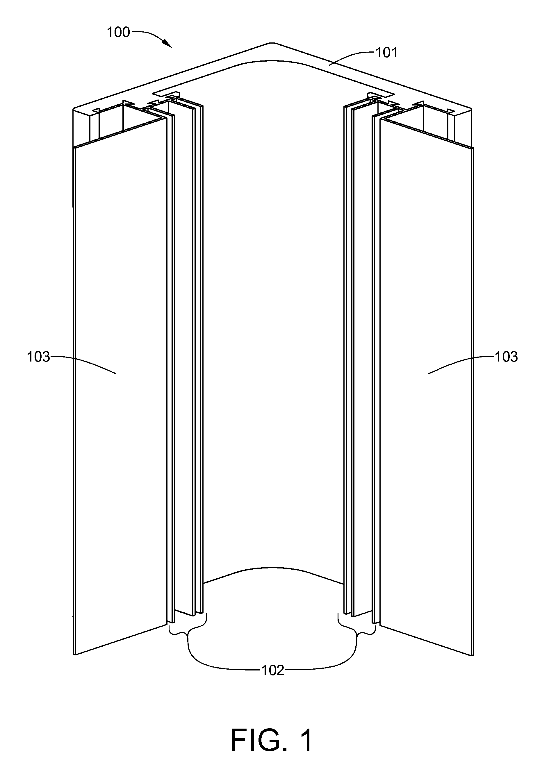
[0031] FIG. 1 is an isometric view of a co-extruded outside corner;
[0032] FIG. 2 is a cross-sectional view of the co-extruded outside corner;
[0033] FIG. 3 is an isometric view of a co-extruded inside corner;
[0034] FIG. 4 is a cross-sectional view of the co-extruded inside corner;
[0035] FIG. 5 is an isometric view of a co-extruded door trim;
[0036] FIG. 6 is a cross-sectional view of the co-extruded door trim;
[0037] FIG. 7 is an isometric view of a co-extruded window trim and stand-off bracket;
[0038] FIG. 8 is a cross-sectional view of the co-extruded window trim;
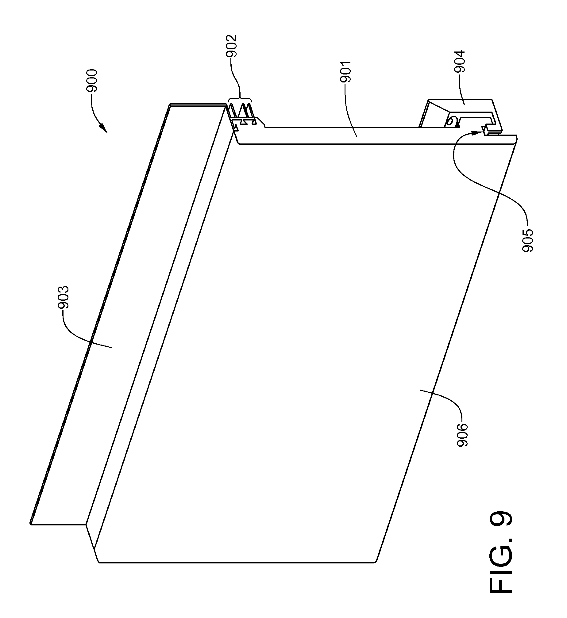
[0039] FIG. 9 is an isometric view of a co-extruded apron designed for use with clapboard siding;
[0040] FIG. 10 is a cross-sectional view of the co-extruded apron of FIG. 9;
[0041] FIG. 11 is an isometric view of a co-extruded apron designed for use with board-and-batten siding;
[0042] FIG. 12 is a cross-sectional view of the co-extruded apron of FIG. 11;
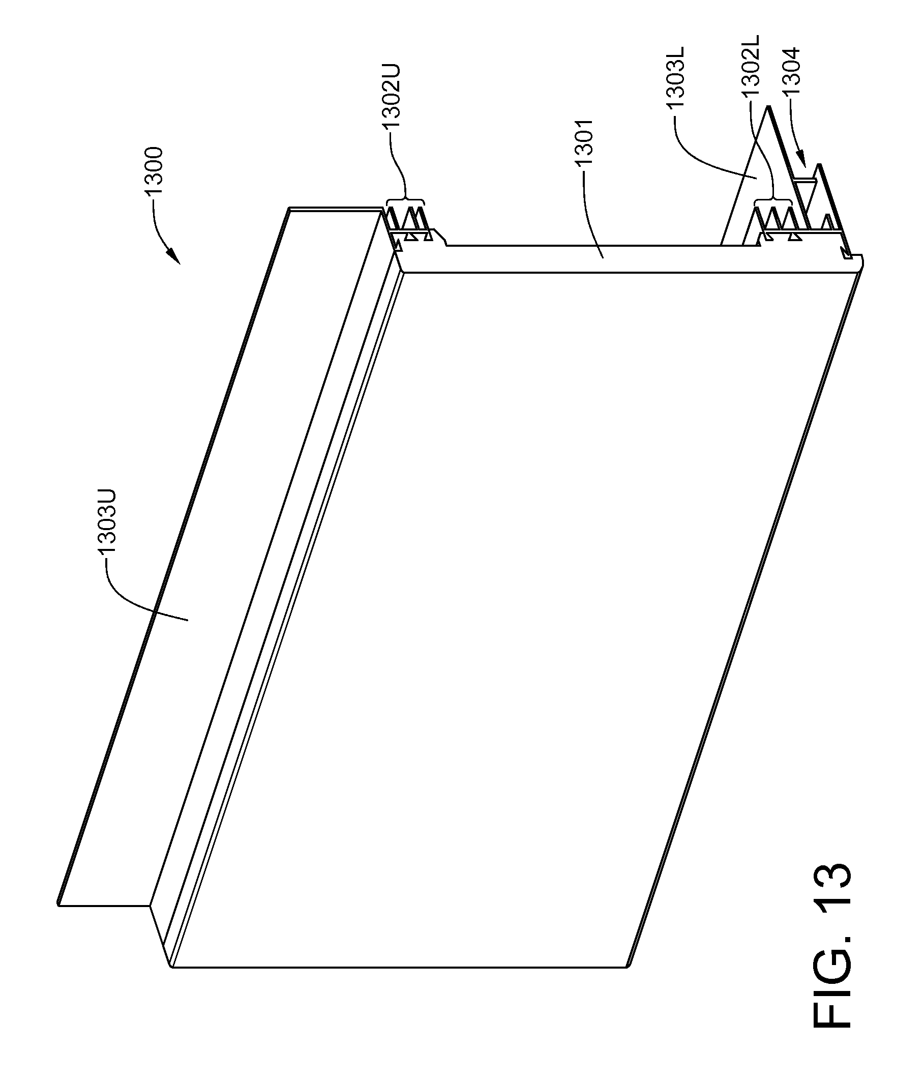
[0043] FIG. 13 is an isometric view of an apron for use with cantilevered floors and clapboard siding;
[0044] FIG. 14 is a cross-sectional view of the co-extruded apron of FIG. 13;
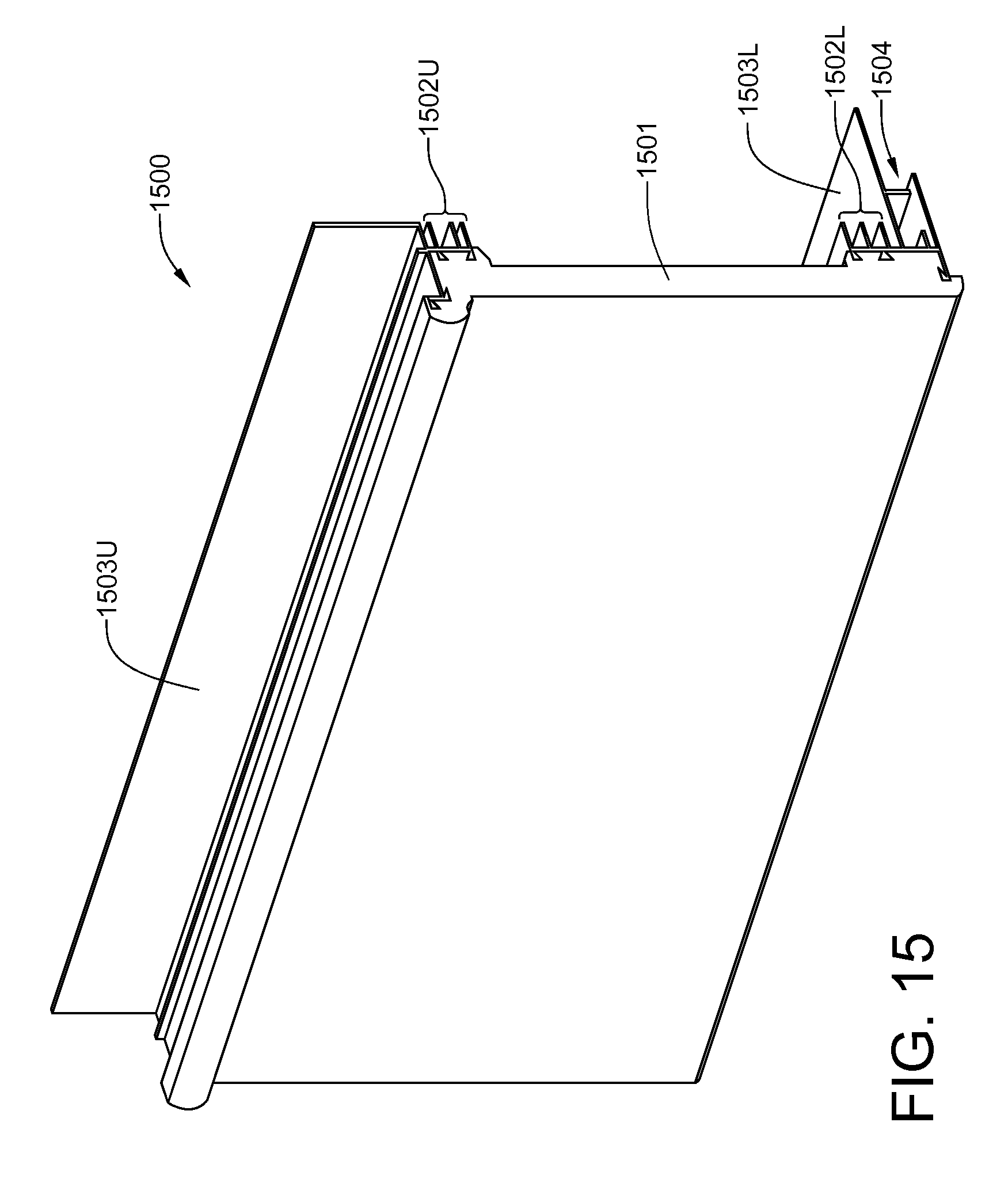
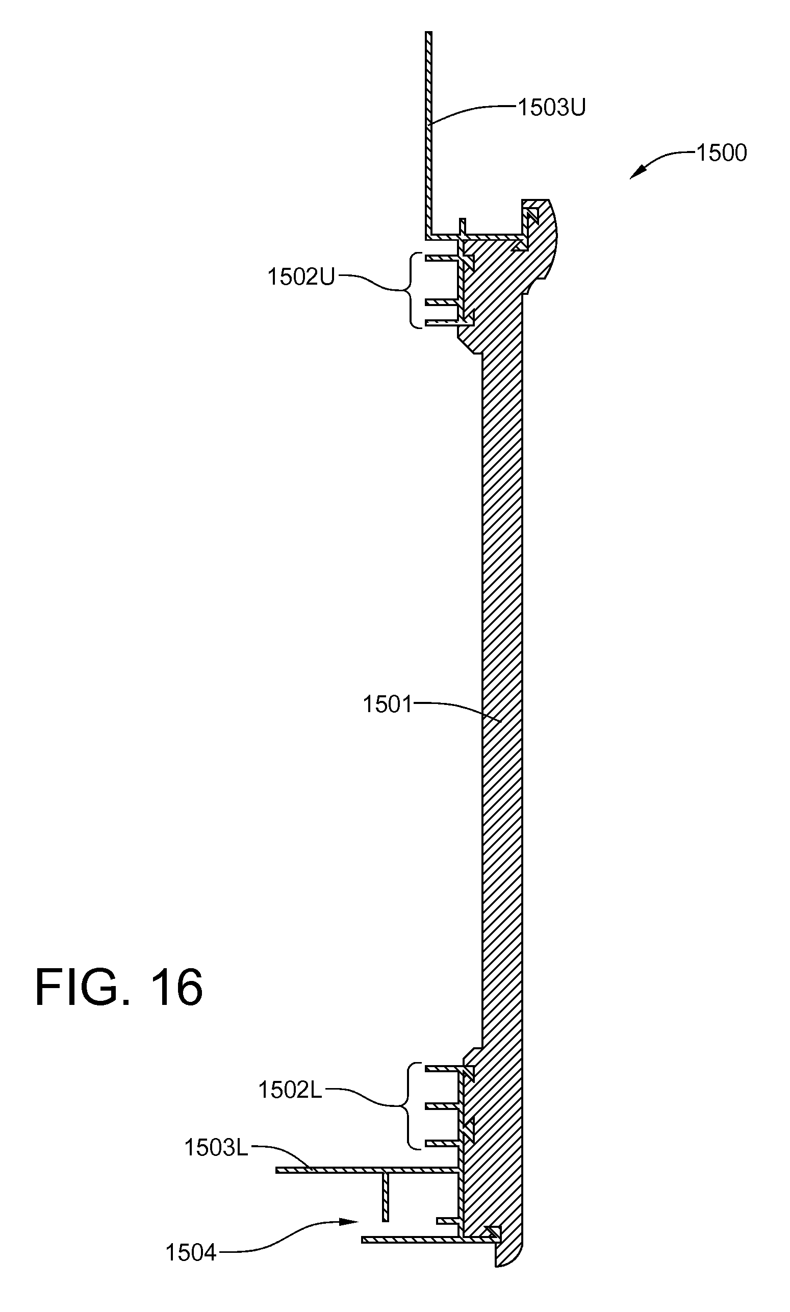
[0045] FIG. 15 is an isometric view of an apron for use with cantilevered floors and board-and-batten siding;
[0046] FIG. 16 is a cross-sectional view of the co-extruded apron of FIG. 15;
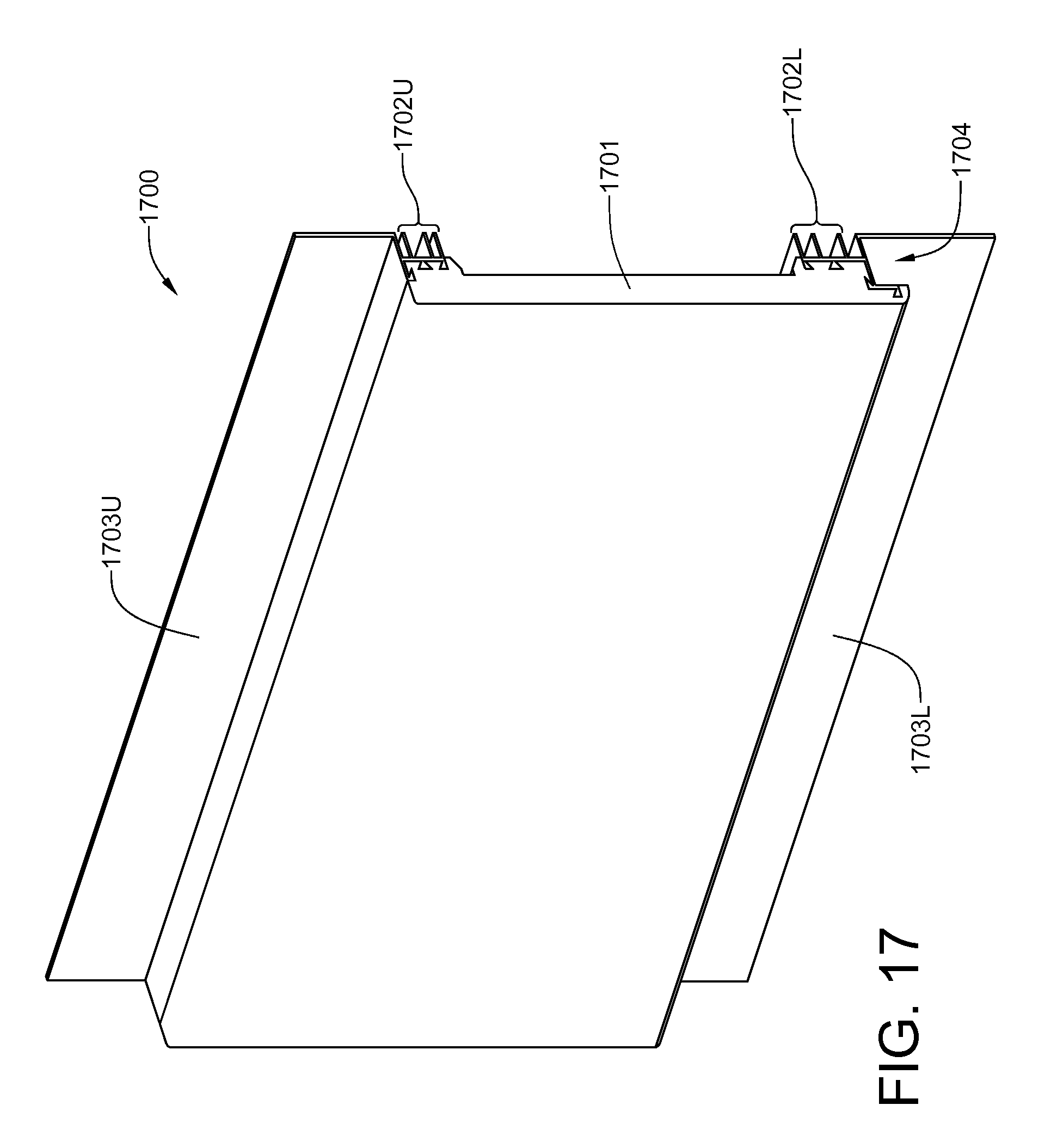
[0047] FIG. 17 is an isometric view of a co-extruded mid-wall apron used with clapboard siding both above it and below it;
[0048] FIG. 18 is a cross-sectional view of the co-extruded mid-wall apron of FIG. 17;
[0049] FIG. 19 is an isometric view of a co-extruded mid-wall apron used with board-and-bat siding both above it and below it;
[0050] FIG. 20 is a cross-sectional view of the co-extruded mid-wall apron of FIG. 19;
[0051] FIG. 21 is an isometric view of a co-extruded mid-wall apron used with board-and-bat siding below it and clapboard siding above it;
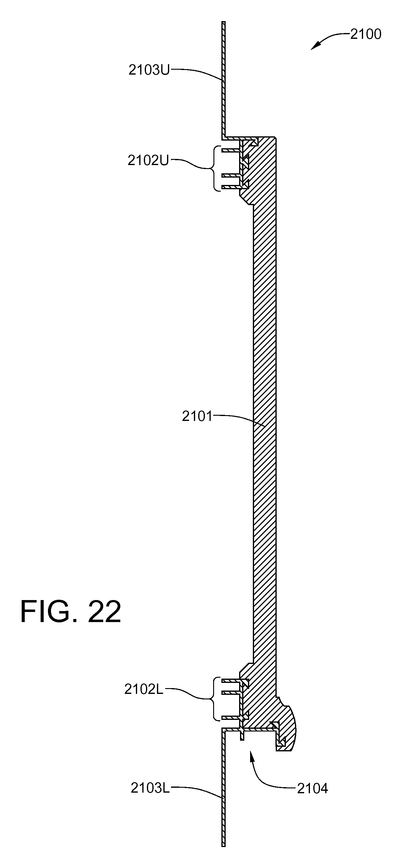
[0052] FIG. 22 is a cross-sectional view of the co-extruded mid-wall apron of FIG. 21;
[0053] FIG. 23 is an isometric view of a co-extruded mid-wall apron used with clapboard siding below it and board-and-bat siding above it;
[0054] FIG. 24 is a cross-sectional view of the co-extruded mid-wall apron of FIG. 23;
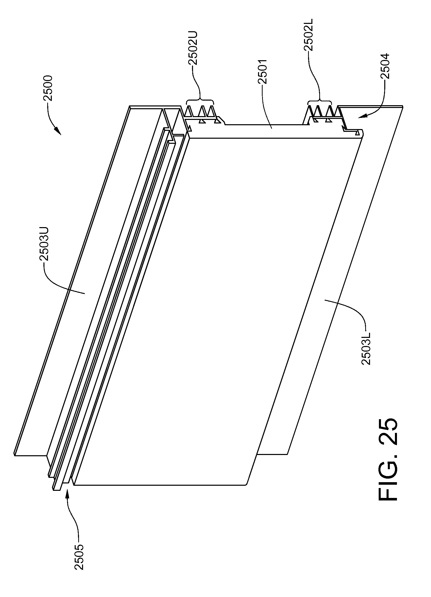
[0055] FIG. 25 is an isometric view of a co-extruded frieze board designed for horizontal use in combination with clapboard siding;
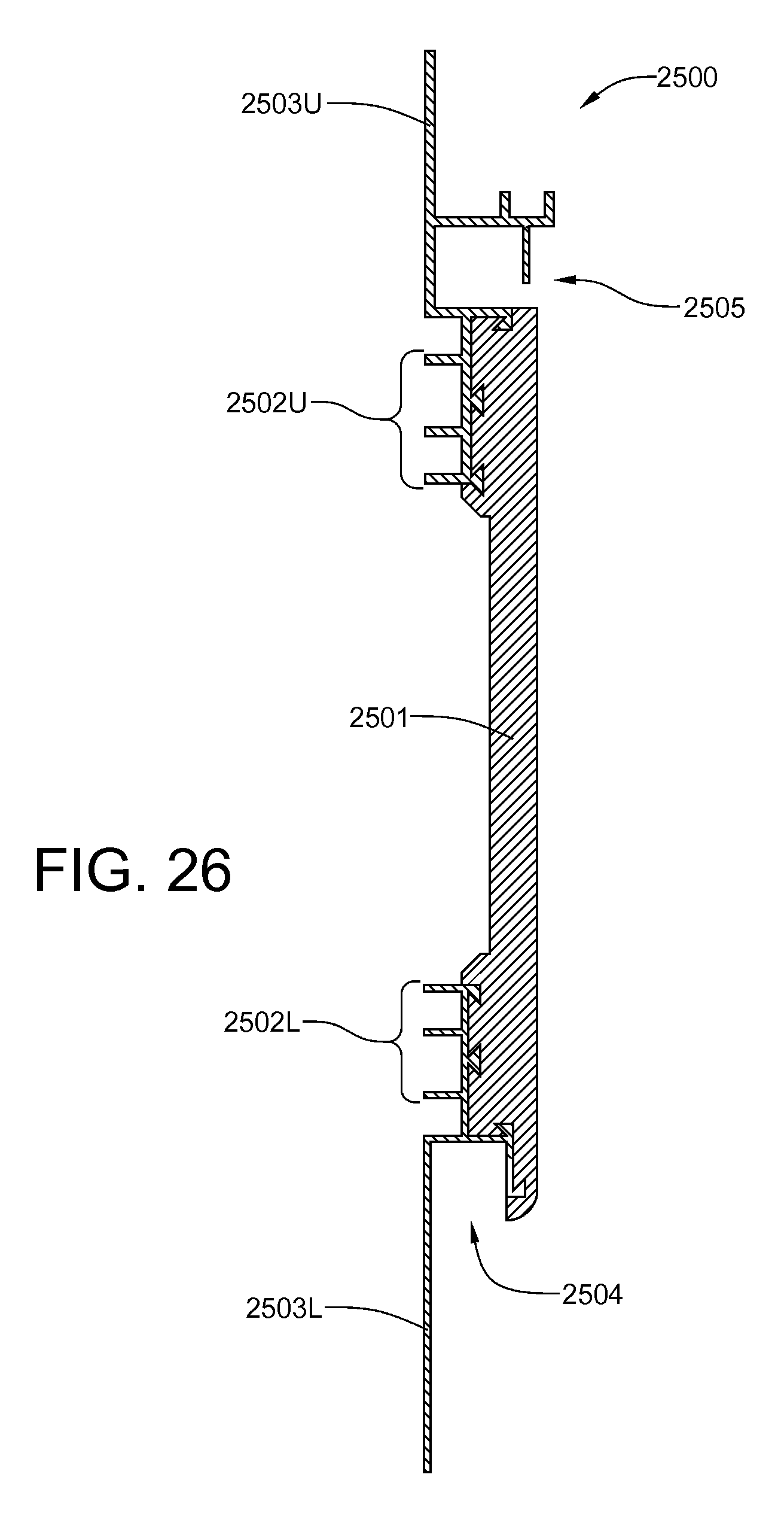
[0056] FIG. 26 is a cross-sectional view of the co-extruded frieze board of FIG. 25;
[0057] FIG. 27 is an isometric view of a co-extruded frieze board designed for horizontal use in combination with board-and-batten siding;
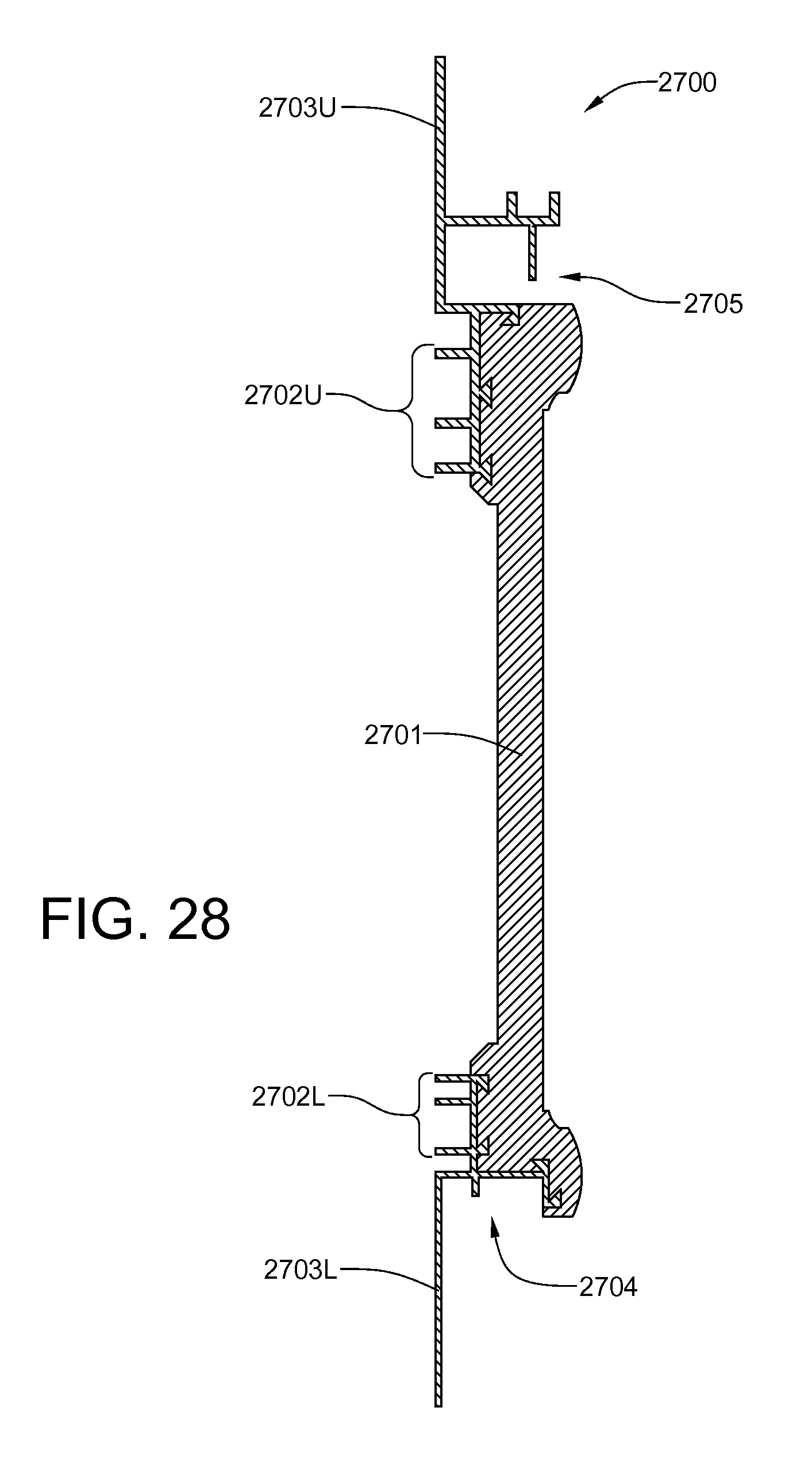
[0058] FIG. 28 is a cross-sectional view of the co-extruded frieze board of FIG. 27;
[0059] FIG. 29 is an isometric view of a co-extruded gable frieze board;
[0060] FIG. 30 is a cross-sectional view of the co-extruded gable frieze board;
[0061] FIG. 31 is an isometric view of an extruded of fascia board;
[0062] FIG. 32 is a cross-sectional view of the extruded fascia board;
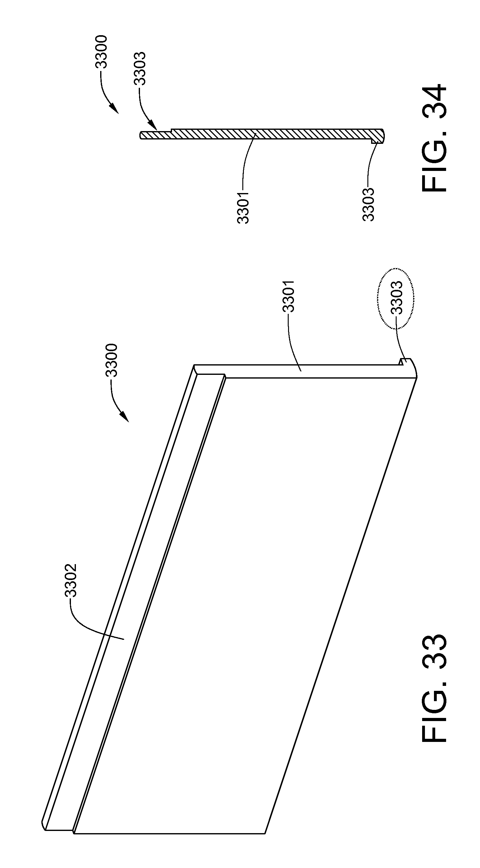
[0063] FIG. 33 is an isometric view of an extruded clapboard;
[0064] FIG. 34 is a cross-sectional view of the extruded clapboard;
[0065] FIG. 35 is an isometric view of a co-extruded combination board and batten used for vertically-oriented board-and-batten siding with battens of rounded cross section;
[0066] FIG. 36 is a cross-sectional view of the co-extruded combination board and batten of FIG. 35;
[0067] FIG. 37 is an isometric view of a co-extruded combination board and batten used for vertically-oriented board-and-batten siding with battens of squared cross section;
[0068] FIG. 38 is a cross-sectional view of the co-extruded combination board and batten of FIG. 37;
[0069] FIG. 39 is an isometric view of a mullion used to eliminate siding butt joints;
[0070] FIG. 40 is a cross-sectional view of the mullion;
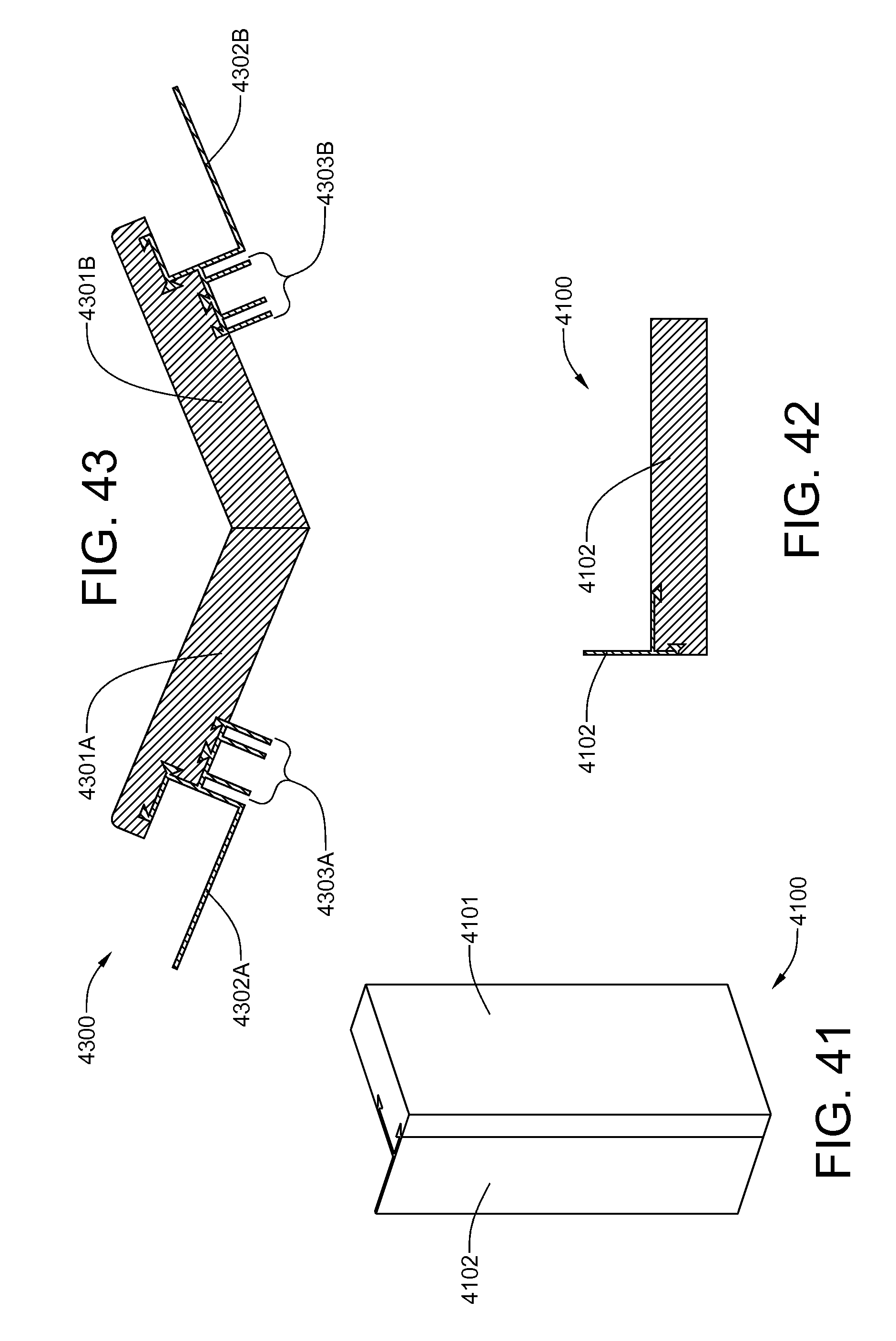
[0071] FIG. 41 is an isometric view of a filler piece used for the overhead door trim installation in FIG. 51;
[0072] FIG. 42 is a cross-sectional view of the filler piece;
[0073] FIG. 43 is an isometric view of a custom corner trim piece;
[0074] FIG. 44 is an isometric view of an apron support bracket;
[0075] FIG. 45 is a rear view of the apron support bracket;
[0076] FIG. 46 is a siding starter clip with a 3M VHB adhesive pad;
[0077] FIG. 47 is a rear view of the starter clip of FIG. 46;
[0078] FIG. 48 is an isometric view of a siding clip with a VHB adhesive pad;
[0079] FIG. 49 is a rear view of the siding clip of FIG. 48;
[0080] FIG. 50 is a support bracket for the custom corner;
[0081] FIG. 51 is a top view of garage door in which standard corner trim pieces are used in combination with spacer battens; and
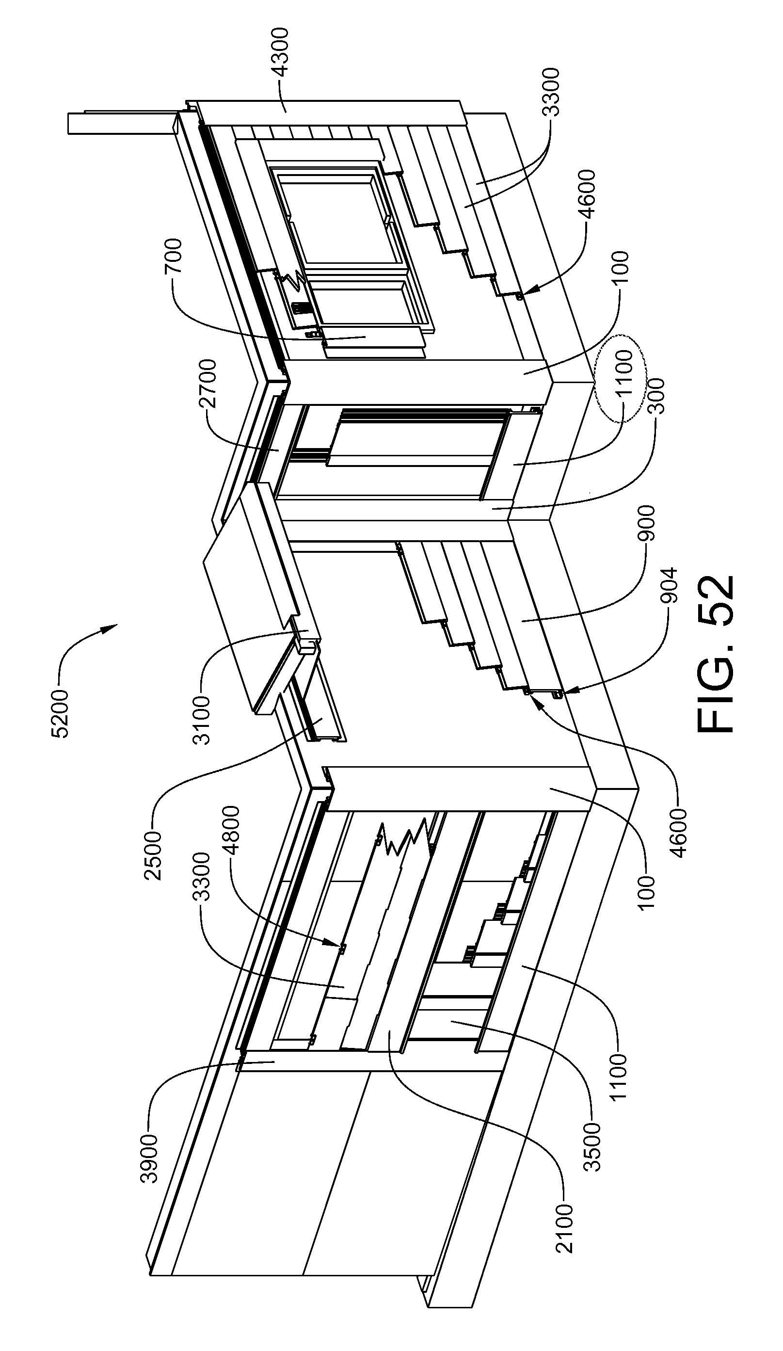
[0082] FIG. 52 is an assembly wall showing the siding and trim applied to a building.
DETAILED DESCRIPTION OF THE INVENTION
[0083] The present invention provides a lapboard siding and trim system in which trim siding components for board-and-batten siding and associated trim components are manufactured using a co-extrusion process, whereby wood/thermoplastic resin composite material and polyvinyl chloride thermoplastic resins are co-extruded through a single die assembly, thereby producing a trim piece having a plastic composite component, that will be visible following installation, fused under heat and pressure to the polyvinyl chloride standoff and attachment fins, that will be hidden following installation. The result is a fully-assembled lapboard siding trim piece with standoff and attachment fins formed as a completely waterproof, single unit of maximum structural integrity. The structural integrity of these siding and trim components is such that they can withstand winds up to 200 miles per hour. When the cost of the extrusion dies are amortized over a production run, the cost of trim pieces so formed is substantially less than the cost of similar trim pieces manufactured in a process whereby the trim piece and standoff and attachment fins are extruded in separate processes and subsequently joined together using adhesives or mechanical fastening techniques. In addition, installation costs are substantially reduced, not only because the trim components are light weight and fully assembly upon arrival at the job site, but they require thirty percent less nailing than standard trim components. The present invention also provides a lapboard siding and trim system in which siding components for clapboard siding are manufactured by extruding wood/thermoplastic resin composite material through a die. Associated trim components are manufactured using the coextrusion process described above. Some of the trim components for both siding systems are identical, while others are manufactured with gap spacings specifically tailored to the particular system.
[0084] The lapboard siding and trim system of the present invention is designed to be almost completely devoid of face-nailed components. Only the topmost lapboard requires face nailing, and only one edge of exterior door requires face nailing. This almost complete absence of face nailing not only provides a much cleaner appearance, but also eliminates the need to caulk and paint face-nailed siding and trim components. The enhanced appearance brought about by the almost complete elimination of face nailing of siding and trim components endures for the life of the siding and trim, which is expected to be at least fifty years and, likely, double that period. Given that installation mistakes are far less likely to occur using fully-assembled trim components, fifty year warranties can be provided to original owners and their successors in interest with minimal risk.
[0085] A further advantage of the present siding and trim system is that the standoff and attachment fins on trim pieces is flexible, thereby enabling most trim pieces to move within a limited range as the siding components expand and contract as a result of variations in temperature and/or humidity. The expansion and contraction of siding and trim components incurs neither structural nor cosmetic damage over time.
[0086] The present invention provides a complete lapboard siding and trim system, and includes components to cover the entire structure, from the fascia down to the foundation. The following trim components are provided in connection with the present invention: outside corner trim, inside corner trim, apron trim, batten apron trim, frieze board trim used for clapboard siding, frieze board trim used for board-and-batten siding, door trim, window trim, fascia trim, round batten trim, square batten trim, and gable frieze board trim. In addition, a standoff bushing is provided for use in connection with the co-extruded window trim, and an apron support clip is used in connection with the co-extruded apron trims. For a presently preferred embodiment of the invention, the bushing and clip are manufactured from ABS thermoplastic resin.
[0087] The siding and trim system of the present invention represents a revolutionary advance in the art, in that it solves problems inherent to lapboard siding and trim that have remained largely unaddressed for over 100 years. This new siding and trim system eliminates virtually all face nailing, which is still standard practice for lapboard siding and associated trim. Pin nailing, which is required only on one edge of door trim and on topmost trim or lapboards, is barely detectable. In addition, the new siding and trim system completely eliminates the need for caulking. Filling of pin-nailed components is optional. The new siding and trim system is designed so that any mistakes in installation will result in merely cosmetic, rather than structural defects.
[0088] The present invention provides a lapboard siding and trim system that is designed to breathe, so that moisture can drain away from the weather barrier before it wicks into the interior structure. All of the siding and trim pieces are spaced away from the weather barrier that covers the sheathing and frame structure of the building, thereby leaving a gap that is continuous from the top of the structure to the foundation. Any water that penetrates the siding and trim components and ends up within this gap drains to vents at the very bottom of the siding and trim system, where it is expelled to the exterior. Any residual moisture in the gap evaporates through the action of air currents generated by winds and breezes. By allowing the siding and trim system to breathe, the sheathing and underlying frame structure of the building is much better protected against the incursion of water and moisture than they would be if a "sealed" siding and trim system were employed. One huge advantage of the present system is caulking is not used as a sealant, but only to hide face nails in a very few locations. This dramatically lowers installation costs and also eliminates the need to recaulk a structure after oxidation, heat and light have caused caulking to fail from deterioration and shrinkage.
[0089] The lapboard siding and trim system, which is aimed specifically at the single-family, multi-family, residential and small commercial markets, will now be described in detail with reference to the attached drawing FIGS. 1 through 53. It should be understood that the drawings are meant to be merely illustrative of the system and may not be drawn to scale.
[0090] Referring now to FIGS. 1 and 2, a co-extruded outside corner trim piece 100 includes a wood fiber/thermoplastic resin composite material (hereinafter, "composite material") outside corner trim body 101, polyvinyl chloride (hereinafter, "PVC") standoffs 102 and PVC attachment fins 103. The composite material and the PVC are two different materials that are molecularly joined via heat fusion during the co-extrusion process. The co-extruded outside corner trim piece 100, like all of the trim pieces disclosed herein are unitary in structure. The two different materials are required for proper functioning of the trim pieces. The composite material has several functions: prevent ultraviolet radiation from attacking the barrier layer in which the underlying structure is wrapped for water and wind resistance; provide an aesthetically pleasing shell around the underlying structure that absorbs mechanical blows that would otherwise damage that structure; and create a ventilated air gap between the shell and the underlying structure that is of paramount importance in keeping moisture from wicking into the interior structure. The PVC components of the trim piece 100 not only enables secure anchoring of the trim piece 100 to the underlying structure, but provides the standoffs which create the ventilated air gap. In addition, the PVC components are also flexible and have memory, which allows the siding components to expand and contract within an expected range, without damaging the trim piece 100. No part of the trim body 101 will be directly attached to the interior structure of the building. This is true for all trim components, except for the door trim, which will be hereinafter described.
[0091] Referring now to FIGS. 3 and 4, a co-extruded inside corner trim piece 300 includes a composite material inside corner trim body 301, PVC standoffs 302 and PVC attachment fins 303. The inside corner trim piece 300 is attached to the internal structure in the same manner that the outside corner piece 100 is attached thereto. The composite and PVC portions also function in a like manner.
[0092] Referring now to FIGS. 5 and 6, a co-extruded door trim piece 500 includes a composite material door trim body 501, PVC standoffs 502 and a PVC attachment fin 503. The door trim piece 500 is one of the few pieces which employs face nailing for attachment to the door framing, but only on the inner edge 504 thereof. Referring now to FIGS. 7 and 8, a co-extruded window trim piece 700 includes a composite material window trim body 701, PVC standoffs 702 and a PVC attachment fin 703. The attachment fin 703 is nailed or stapled along its length to the underlying structure of the building. The inner edge of the trim (i.e., the edge adjacent the edge of the window, overlies the window fin and is attached with standoff brackets 704 at the top and bottom thereof. Thus, the inner edge of the window trim piece 700 is attached in a cantilevered manner.
[0093] Referring now to FIGS. 9 and 10, the co-extruded apron trim piece 900 is intended for use with clapboard siding, and includes a composite material apron trim body 901, PVC standoffs 902 and a PVC upper attachment fin 903. This apron trim piece 900 is designed to be the first siding, or trim, component above the building's foundation. The lower edge of the apron trim piece 900 is secured (preferably screwed) to the underlying structure of the building with a hanger clip 904, which engages a hidden channel 905 on the lower back side of the apron trim piece 900. The first course of clapboard siding covers the upper attachment fin 903.
[0094] Referring now to FIGS. 11 and 12, the co-extruded apron trim piece 1100 is intended for use with board-and-batten siding, and includes a composite material apron trim body 1101, PVC standoffs 1102 and a PVC upper attachment fin 1103. The lower edge of the apron trim piece 1100 is secured (preferably screwed) to the underlying structure of the building with a hanger clip 904, which engages a hidden channel on the lower back side of the apron trim piece 1100. This apron trim piece 1100 is also designed to be the first siding, or trim, component above the building's foundation. The apron trim piece 1100 differs from that of FIGS. 9 and 10 in that it has an upward facing channel that hides the cut ends of the board-and-batten siding.
[0095] Referring now to FIGS. 13 and 14, the co-extruded apron trim piece 1300 is designed for the starter course at the bottom of a cantilevered floor, is intended for use with clapboard siding, and includes a composite material apron trim body 1301, PVC standoffs 1302 and upper and lower PVC attachment fins 1303U and 1303L. The upper attachment fin 1303U is nailed or stapled to the wall, while the lower attachment fin 1303L is secured to the underside of the cantilevered floor. The first course of clapboard siding covers the upper attachment fin 1303U. A rear-facing groove 1304 at the bottom of this apron trim piece 1300 receives an edge of a soffit panel.
[0096] Referring now to FIGS. 15 and 16, the co-extruded apron trim piece 1500 is designed for installation on the bottom of a cantilevered floor, is intended for use with board-and-batten siding, and includes a composite material apron trim body 1501, PVC standoffs 1502 and upper and lower PVC attachment fins 1503U and 1503L. The upper attachment fin 1503U is nailed or stapled to the wall, while the lower attachment fin 1503L is secured to the underside of the cantilevered floor. The cut lower ends of the board-and-batten siding fit within the groove 1504 at the top of the apron trim body 1501. A rear-facing groove 1504 at the bottom of this apron trim piece 1500 receives an edge of a soffit panel.
[0097] Referring now to FIGS. 17 and 18, the co-extruded mid-wall apron 1700, which is designed to accommodate clapboard siding both above and below it, includes a composite material apron trim body 1701, PVC standoffs 1702 and upper and lower PVC attachment fins 1703U and 1703L. Both attachment fins 1703U and 1703L are nailed or stapled to the wall. The first clapboard of the upper course covers the upper attachment fin 1703, while the downward facing groove at the bottom of the apron trim body 1701 hides the upper edge of the last clapboard of the lower course.
[0098] Referring now to FIGS. 19 and 20, the co-extruded mid-wall apron 1900, which is designed to accommodate board-and-batten siding both above and below it, includes a composite material apron trim body 1901, PVC standoffs 1902 and upper and lower PVC attachment fins 1903U and 1903L. Both attachment fins 1903U and 1903L are nailed or stapled to the wall. The cut upper ends of the board-and-batten siding of the lower course fit into the downward-facing 1904 at the bottom of the apron trim body 1901. Likewise, the cut lower ends of the board-and-batten siding of the upper course fit within the upward-facing groove 1905 at the top of the apron trim body 1901.
[0099] Referring now to FIGS. 21 and 22, the co-extruded mid-wall apron 2100, which is designed to accommodate board-and-batten siding below it and clapboard siding above it, includes a composite material apron trim body 2101, PVC standoffs 2102 and upper and lower PVC attachment fins 2103U and 2103L. Both attachment fins 2103U and 2103L are nailed or stapled to the wall. The cut upper ends of the board-and-batten siding of the lower course fit into the downward-facing groove 2104 at the bottom of the apron trim body 2101. The first course of the clapboard siding covers the upper attachment fin 2103U.
[0100] Referring now to FIGS. 23 and 24, the co-extruded mid-wall apron 2300, which is designed to accommodate clapboard siding below it and board-and-batten siding above it, includes a wood fiber/thermoplastic resin composite material (hereinafter, "composite material") apron trim body 2301, PVC standoffs 2302 and upper and lower PVC attachment fins 2303U and 2303L. Both attachment fins 2303U and 2303L are nailed or stapled to the wall. The upper edge of the last course of the clapboard siding below is covered by the downward-facing groove 2304 at the bottom of the apron trim body 2301. In addition, the cut lower ends of the board-and-batten siding of the upper course fit within the upward-facing groove 2305 at the top of the apron trim body 2301.
[0101] Referring now to FIGS. 25 and 26, the co-extruded frieze board 2501, which is designed to accommodate clapboard siding below it, includes a composite material frieze board body 2501, PVC standoffs 2502 and upper and lower PVC attachment fins 2503U and 2503L. The upper edge of the last course of the clapboard siding below is covered by the downward-facing groove 2504 at the bottom of the frieze board trim body 2501. An outwardly-facing groove 2505 at the top of the frieze board trim body 2501 receives an edge of a soffit panel.
[0102] Referring now to FIGS. 27 and 28, the co-extruded frieze board 2701, which is designed to accommodate board-and-batten siding below it, includes a composite material frieze board body 271, PVC standoffs 2702 and upper and lower PVC attachment fins 2703U and 2703L. The downward-facing groove 2704 at the bottom of the frieze board trim body 2701 covers the upper cut ends of the board-and-batten siding. An outwardly-facing groove 2705 at the top of the frieze board trim body 2701 receives an edge of a soffit panel.
[0103] Referring now to FIGS. 29 and 30, the co-extruded gable frieze board 2901, which is designed to accommodate both clapboard and board-and-batten siding below it, includes a composite material frieze board body 2901, PVC standoffs 2902 and upper and lower PVC attachment fins 2903U and 2903L. The downward-facing groove 2904 at the bottom of the gable frieze trim body 2901 is sufficiently wide to cover either the upper cut ends of the board-and-batten siding or overlapping boards of clapboard siding. An outwardly-facing groove 2905 at the top of the frieze board trim body 2901 receives an edge of a soffit panel.
[0104] Referring now to FIGS. 31 and 32, the extruded fascia board 3100 has only a composite material fascia board body 3101. It is the only trim component that has no PCV standoffs and fins attached. The outwardly-extending shelf 3102 is screwed to the bottom of the fascia board. The groove below the shelf 3102 receives an edge of the soffit panel (not shown). The soffit panels are preferably formed by extruding the composite material between a pair of closely spaced rollers. The material is preferably about 0.375 inch thick and is manufactured in 6-inch, 12-inch, 18-inch and 24-inch widths.
[0105] Referring now to FIGS. 33 and 34, an extruded clapboard 3300 has only a composite material body, with no PVC standoffs and fins attached. The upper edge is reduced in thickness to accommodate an attachment clip. The use of attachment clips is covered in U.S. patent application Ser. No. 12/416,762, which was filed on Apr. 1, 2009 by the same inventor. A new feature in this application is the inner lower edge has a longitudinal rib which is pulled up flush against the attachment clip of the immediately adjacent lower clapboard course, thereby eliminating the need for measurement once the first course is leveled.
[0106] Referring now to FIGS. 35 and 36, a first embodiment co-extruded combination board-and-batten board 3500 is designed for rapid installation. The single attachment fin 3501 on each board 3500 is attached to the underlying structure. Thus, only one edge of each board 3500 is secured directly to the substrate. The other edge is held in place by the groove beneath the simulated batten 3502. This particular board 3500 has a simulated batten 3502 with rounded edges.
[0107] Referring now to FIGS. 37 and 38, a second embodiment co-extruded combination board-and-batten board 3700 is designed for rapid installation. The single attachment fin 3701 on each board 3700 is attached to the underlying structure. Thus, only one edge of each board 3700 is secured directly to the substrate. The other edge is held in place by the groove beneath the simulated batten 3702. This particular board 3700 has a simulated batten 3702 with square edges.
o CE-7: Is a drawing of the Fascia (used to receive soffit panel, and cover fascia. see drawing CE-W). Showing both the wood plastic composite, and the PVC materials being married through heat fusion as they are co-extruded simultaneously. They are two completely different materials, co-extruded together. Resulting in an individual part being one piece, two different materials. The two different materials are necessary for the performance of the Part, both structurally and for expansion and contraction "reaction memory". The wood plastic composite or body will be sand blasted to allow for maximum paint adhesion both textured and smooth finishes (Note: The PVC extrusion has a soffit receiver similar to the opposing frieze board. They level line across from one another. The bottom PVC extrusion is for receiving the opposing end of the soffit panel by first inserting the soffit panel into the frieze board. Then just like a zip loc bag, you simply hem the fascia board into place locking in the soffit panel. Then by inserting a blind nail at the top of the frieze board, about 1'' from the top. The roofing drip edge will cover the nail head. Then nail or screw through the soffit panel, through the extrusion at 32'' O.C. (See drawing CE-W). All of the parts have stand offs on the backside of the PVC extrusions and ABS injections. That will hold the wood composite material off of the substrate, or structures, plywood or sheer panels act. Thus creating air flow between the back side of the Co-X Trim System, and the actual structure. (Air movement or air flow in between structure and The Co-X Trim System). Meaning the only contact between the Co-X Trim System, and the actual structure. Would be the points of contact, of the PVC extrusions, and the points of contact between the ABS Injection parts. There is no where that water can stand and wick into the wood plastic composite. Water is ejected by mother nature/gravity due to the stand offs, giving it no place to be trapped in the wall. Secure/nail through the PVC nail fins. Meaning no face nailing or no nailing through the wood plastic composite material. Screws attach ABS injection parts accordingly. (Note: Co-X Trim System aprons, frieze boards, board & batten all tuck into the inside and outside corners, with the exception of the gable frieze board). o CE-8: Is a drawing of the Round Batten (used for board& batten, see drawing CE-W). Showing both the wood plastic composite, and the PVC materials being married through heat fusion as they are co-extruded simultaneously. They are two completely different materials, co-extruded together. Resulting in an individual part being one piece, two different materials. The two different materials are necessary for the performance of the Part, both structurally and for expansion and contraction "reaction memory". The wood plastic composite or body will be sand blasted to allow for maximum paint adhesion both textured and smooth finishes (Note: there is one batten co-extruded to the wood plastic composite panel for the board and batten. There are two standing ribs on the back of the panels that function for air flow as well as for use with the table saw allowing it to be much safer for the installer to rip cut. They keep the wood plastic composite off the substrate allowing for no water entrapment. The board & batten generally will terminate into a frieze board at the top and an apron on the bottom, but there are varying combinations in which it can be installed. See drawing CE-W). All of the parts have stand offs on the backside of the PVC extrusions and ABS injections. That will hold the wood composite material off of the substrate, or structures, plywood or sheer panels act. Thus creating air flow between the back side of the Co-X Trim System, and the actual structure. (Air movement or air flow in between structure and The Co-X Trim System). Meaning the only contact between the Co-X Trim System, and the actual structure. Would be the points of contact, of the PVC extrusions, and the points of contact between the ABS Injection parts. There is no where that water can stand and wick into the wood plastic composite. Water is ejected by mother nature/gravity due to the stand offs, giving it no place to be trapped in the wall. Secure/nail through the PVC nail fins. Meaning no face nailing or no nailing through the wood plastic composite material. Screws attach ABS injection parts accordingly. (Note: Co-X Trim System aprons, frieze boards, board & batten all tuck into the inside and outside corners, with the exception of the gable frieze board). o CE-8A: Is a 3D drawing of the Round Batten (used for board& batten, see drawing CE-W). o CE-9: Is a drawing of the Square Batten, same as CE-8 only square (used for board& batten, see drawing CE-W). Showing both the wood plastic composite, and the PVC materials being married through heat fusion as they are co-extruded simultaneously. They are two completely different materials, co-extruded together. Resulting in an individual part being one piece, two different materials. The two different materials are necessary for the performance of the Part, both structurally and for expansion and contraction "reaction memory". The wood plastic composite or body will be sand blasted to allow for maximum paint adhesion both textured and smooth finishes (Note: there is one batten co-extruded to the wood plastic composite panel for the board and batten. There are two standing ribs on the back of the panels that function for air flow as well as for use with the table saw allowing it to be much safer for the installer to rip cut. They keep the wood plastic composite off the substrate allowing for no water entrapment. The board & batten generally will terminate into a frieze board at the top and an apron on the bottom, but there are varying combinations in which it can be installed. See drawing CE-W). All of the parts have stand offs on the backside of the PVC extrusions and ABS injections. That will hold the wood composite material off of the substrate, or structures, plywood or sheer panels act. Thus creating air flow between the back side of the Co-X Trim System, and the actual structure. (Air movement or air flow in between structure and The Co-X Trim System). Meaning the only contact between the Co-X Trim System, and the actual structure. Would be the points of contact, of the PVC extrusions, and the points of contact between the ABS Injection parts. There is no where that water can stand and wick into the wood plastic composite. Water is ejected by mother nature/gravity due to the stand off's, giving it no place to be trapped in the wall. Secure/nail through the PVC nail fins. Meaning no face nailing or no nailing through the wood plastic composite material. Screws attach ABS injection parts accordingly. (Note: Co-X Trim System aprons, frieze boards, board & batten all tuck into the inside and outside corners, with the exception of the gable frieze board). o CE-10: Is a drawing of the Gable Frieze Board (used for siding and board & batten,). Showing both the wood plastic composite, and the PVC materials being married through heat fusion as they are co-extruded simultaneously. They are two completely different materials, co-extruded together. Resulting in an individual part being one piece, two different materials. The two different materials are necessary for the performance of the Part, both structurally and for expansion and contraction "reaction memory". The wood plastic composite or body will be sand blasted to allow for maximum paint adhesion both textured and smooth finishes (Note: The top PVC extrusion has a soffit receiver. The bottom PVC extrusion can be for either for the siding termination at the bottom of the frieze board, or the board & batten. It is a little thicker than the standard frieze board so it will fit flush with the corners. See drawing CE-W). All of the parts have stand offs on the backside of the PVC extrusions and ABS injections. That will hold the wood composite material off of the substrate, or structures, plywood or sheer panels act. Thus creating air flow between the back side of the Co-X Trim System, and the actual structure. (Air movement or air flow in between structure and The Co-X Trim System). Meaning the only contact between the Co-X Trim System, and the actual structure. Would be the points of contact, of the PVC extrusions, and the points of contact between the ABS Injection parts. There is no where that water can stand and wick into the wood plastic composite. Water is ejected by mother nature/gravity due to the stand off's, giving it no place to be trapped in the wall. Secure/nail through the PVC nail fins. Meaning no face nailing or no nailing through the wood plastic composite material. Screws attach ABS injection parts accordingly. (Note: Co-X Trim System aprons, frieze boards, board & batten all tuck into the inside and outside corners, with the exception of the gable frieze board). All to receive board & batten. o CE-11 is the ABS Standoff Bushing (used for Co-X window trim) the standoff bushing attaches to the back side of the Co-X window trim using a shallow screw. The standoff bushing allowing for the window trim to bridge over the window nail fin itself. This allows for the Co-X window trim to have a equal parallel reveal where the Co-X window trim abuts the window itself. o CE-12 is the ABS Apron Support Clip (Used for Co-X aprons) the apron support clip is screwed to a level line prior to the installation of the Various Co-X aprons. (see drawing: CE-W CE-3).
[0108] This system concept will eliminate dry-rot and mold, a known fact to cause severe illness due to water entrapment. Because the system is caulk free, it allows for normal expansion and contraction and allowing for air movement between the water barrier/house wrap, and the wood Plastic composite, (trim veneer). Mold and dry-rot are eliminated. The only thing that touches the substrate/house wrap; is the PVC extrusions and the injection parts leaving the wood plastic composite, standing of the substrate, allowing room for air movement between the backside of the veneer and the actual structure. It has top notch curb appeal do to the fact that it is completely caulk and face nail free. Let me list the value benefits.
Co-X Trim Systems Value Adds
[0109] Superior Curb Appeal: no face nailing except finish nails in one side of door casing. [0110] Face Nail Free: no nail head blemishes, no need for paint prepping. Except finish nails heads in one side of door casing. [0111] 94% Less Caulk: there is really no need for caulk structurally. [0112] Dry-rot And Mold Free: a known fact to cause severe illness due to water entrapment. [0113] Expansion and Contraction: allows for extreme expansion and contraction with no structural or cosmetic damage. [0114] Air Movement: air movement between substrate/house wrap and veneer allowing for natural air movement to dry up any moisture. [0115] Ease Of installation: Installs significantly faster do to the fact that you are installing assembled parts, verses field assembling flat 4/4 material. [0116] Meets And Exceeds All National Code Compliance [0117] With Stands Winds Of Over 200 mph [0118] Light Weight: compliments the installation process [0119] 50 Year Warrantee [0120] Significantly Over All Cost Savings [0121] 30 Percent less nailing required [0122] Tremendous Reduction Of liability
[0123] Co-X Trim System with stands greater than hurricane force winds, in excess of 200 mile per hour. The system has been designed to solve the commonly known problems with current methods, like wind shear, excessive caulk, face nailing, water entrapment, expansion and contraction, water ejection, water wicking act. Co-X Trim System is structurally sound and eliminates the need for caulk, and the need to face nail or penetrate the face of the trims exposed face. It has far superior curb appeal; paint preparation and blemishes are significantly reduced due to no face nail heads needed to be prepped before paint, and no need for excessive caulk, reducing the overall cost of paint materials. The system is much more reliable, and will be far less time consuming to install. The System will provide a far superior level of quality for the end result. Co-X will give the Siding and trim Installers, Architects, Builders and the whole siding and trim industry, a new revolutionary way to provide a much stronger and more reliable product, as well as making the process of Trimming a building, much more productive and reliable, and much safer to the consumer. This in return will greatly benefit the contractors and installers financially, and give the builder and home owner a much higher level of quality. The beautiful thing is Co-X is cost competitive, and very easy to install.
[0124] Co-X will be a major player in the insurance industry, because of its 50 year warrantee, abilities to prevent dry-rot and mold, its structural integrity to withstand wind loads, and the cost effectiveness against current methods of trim used today. Co-X trim is also compatible with any current siding products out there, such as James Hardies' Hardie Plank, LP Smartside and many more. Any siding 1/4'' to 1/2'' in thickness will integrate with the Co-X Trim System, including wood siding, cement siding and engineered wood siding and wood plastic composite siding, but not limited to.
The Orders of Installation are as Follows
[0125] First step: Start with installing all the Outside and inside Co-X corners first. (Drawing CE-1 CE-2), then install all, Co-X door and window trim. (Drawing CE-5 CE-6) Nail Through (nail fins) using 1 1/2'' roofing coil nails at 24'' .O.C (typ)
[0126] Second step: Install all Co-X aprons and frieze boards trims, which are tucked into the corners 3/8'' (Apron Drawings CE-3 CE-3A Frieze Board CE-4 CE-4A) Nail Through (nail fins) using 1 1/2'' roofing coil nails at 24'' .O.C (typ)
[0127] Third Step: Install your Fascia and soffit panel systematically together. Use 8d blind nail connection 1'' from the top of fascia, the roofers drip edge will cover the nail head eliminating the need for face nailing or caulk prep. Nail Through wood plastic composite soffit material. Through the bottom of the extrusion into the 2.times.6 sub fascia, see (Drawing CE-W and CE-7)
[0128] Fourth Step: Now you are ready to install your siding or board & batten or siding shingles, it's that easy.
[0129] Please note: This is not a wafer wood trim, nor is it a Cementous or Masonite product; this is a wood plastic composite that will be Co-extruded rather than cut from a larger panel to make trim slats. The Co-X Trim System will have both, a wood textured face and smooth face finish available. Both finishes will be sand blasted to enhance paint adhesion and appearance.
[0130] The system is intended to be a malty piece system, comprising of the complete co-extruded trim components and some ABS injection parts that will be explained in the installation steps below, and through the drawings attached to Provisional Paten Letter.
Co-X System Drawings
[0131] o CE-W: Is a Elevation Diagram of the whole Co-X Trim System, describing the systems co-extrusions and injection molded complete parts and assembly as it is installed on the wall.
* * * * *
D00000
D00001
D00002
D00003
D00004
D00005
D00006
D00007
D00008
D00009
D00010
D00011
D00012

D00013
D00014
D00015
D00016

D00017

D00018

D00019

D00020
D00021

D00022

D00023
D00024
D00025

D00026
D00027

D00028

D00029

D00030
D00031

D00032

D00033

D00034
D00035

D00036

D00037
XML
uspto.report is an independent third-party trademark research tool that is not affiliated, endorsed, or sponsored by the United States Patent and Trademark Office (USPTO) or any other governmental organization. The information provided by uspto.report is based on publicly available data at the time of writing and is intended for informational purposes only.
While we strive to provide accurate and up-to-date information, we do not guarantee the accuracy, completeness, reliability, or suitability of the information displayed on this site. The use of this site is at your own risk. Any reliance you place on such information is therefore strictly at your own risk.
All official trademark data, including owner information, should be verified by visiting the official USPTO website at www.uspto.gov. This site is not intended to replace professional legal advice and should not be used as a substitute for consulting with a legal professional who is knowledgeable about trademark law.