Modelling Plate for a Stereolithography Machine, Stereolithography Machine Using Said Modelling Plate and Tool for Cleaning Said Modelling Plate
Zenere; Sergio
U.S. patent application number 13/517184 was filed with the patent office on 2012-12-27 for modelling plate for a stereolithography machine, stereolithography machine using said modelling plate and tool for cleaning said modelling plate. This patent application is currently assigned to DWS S.R.L.. Invention is credited to Sergio Zenere.
| Application Number | 20120328726 13/517184 |
| Document ID | / |
| Family ID | 42556696 |
| Filed Date | 2012-12-27 |


| United States Patent Application | 20120328726 |
| Kind Code | A1 |
| Zenere; Sergio | December 27, 2012 |
Modelling Plate for a Stereolithography Machine, Stereolithography Machine Using Said Modelling Plate and Tool for Cleaning Said Modelling Plate
Abstract
The invention is a modelling plate (6; 6'; 6'') for a stereolithography machine (1) suited to produce three-dimensional objects (A) through superimposition of a plurality of layers (E) with predefined thickness of a liquid substance (3) that solidifies when subjected to a selective stimulation (4). The plate (6; 6'; 6'') comprises a work surface (7) that supports the object (A) and grooves (8) made in the work surface (7) along a development trajectory (X).
| Inventors: | Zenere; Sergio; (Carre' (VI), IT) |
| Assignee: | DWS S.R.L. Zane' VI |
| Family ID: | 42556696 |
| Appl. No.: | 13/517184 |
| Filed: | January 11, 2011 |
| PCT Filed: | January 11, 2011 |
| PCT NO: | PCT/IB11/00034 |
| 371 Date: | July 26, 2012 |
| Current U.S. Class: | 425/174.4 |
| Current CPC Class: | B33Y 40/00 20141201; B29C 64/245 20170801; B33Y 30/00 20141201; B29C 64/135 20170801 |
| Class at Publication: | 425/174.4 |
| International Class: | B29C 35/08 20060101 B29C035/08 |
Foreign Application Data
| Date | Code | Application Number |
|---|---|---|
| Jan 12, 2010 | IT | VI2010A000004 |
Claims
1) Modelling plate (6; 6'; 6'') for a stereolithography machine (1) suited to produce three-dimensional objects (A) through superimposition of a plurality of layers (E) with predefined thickness of a liquid substance (3) suited to solidify when subjected to a selective stimulation (4), said plate (6; 6'; 6'') comprising a work surface (7) suited to support said object (A), characterized in that it comprises at least one groove (8) made in said work surface (7) along a development trajectory (X).
2) Plate (6; 6'; 6'') according to claim 1), characterized in that the depth (9) of said groove (8) exceeds the predefined thickness of said layers (E).
3) Plate (6; 6'; 6'') according to claim 1) or 2), characterized in that said groove (8) extends to the perimeter edge of said work surface (7) so as to have at least one open end at the level of the lateral surface of said plate (6; 6'; 6'').
4) Plate (6; 6'; 6'') according to claim 3), characterized in that said groove (8) has both ends open at the level of said lateral surface of said plate (6; 6'; 6'').
5) Plate (6; 6'; 6'') according to any of the preceding claims, characterized in that said groove (8) has a uniform cross section (11, 11', 11'') along said development trajectory (X).
6) Plate (6') according to claim 5), characterized in that said cross section (11') has at least one area (12) whose width exceeds the width (10) of said cross section (11') at the level of said work surface (7).
7) Plate (6'') according to claim 5) or 6), characterized in that the profile of said cross section (11'') has a recess (13) on at least one of the side edges of said cross section (11'').
8) Plate (6, 6', 6'') according to any of the preceding claims, characterized in that it comprises a plurality of said grooves (8) parallel to each other.
9) Stereolithography machine (1) for the production of three-dimensional objects, comprising: a tank (2) suited to contain a liquid substance (3) that solidifies when it is subjected to a selective stimulation (4); emission means (5) suited to generate said selective stimulation (4) and to convey it towards said tank (2), characterized in that it comprises a modelling plate (6; 6'; 6'') according to any of the claims from 1) to 8).
10) Machine (1) according to claim 9), characterized in that said plate (6; 6; 6'') is arranged with said work surface (7) facing the bottom (2a) of said tank (2).
11) Machine (1) according to claim 9) or 10), characterized in that it comprises a tool (14) for cleaning said modelling plate (6; 6'; 6''), comprising a supporting body (15) from which at least one elongated element (16) develops, configured so that it can slide inside a corresponding groove (8) of said plate (6; 6'; 6'').
12) Machine (1) according to claim 11), characterized in that said tool (14) comprises a supporting body (15) from which a plurality of elongated elements (16) develop, each one of which is configured so that it can slide inside a corresponding groove (8) of said plate (6; 6'; 6''), said elongated elements (16) being mutually parallel and arranged according to a reference plane (Y) at mutual distances that are the same as the mutual distances between the corresponding grooves (8).
13) Machine (1) according to claim 11) or 12), characterized in that the width (17) of each one of said elongated elements (16) with respect to a direction parallel to said reference plane (Y) is substantially equal to the width (10) of the corresponding groove (8) of said plate (6; 6'; 6'').
14) Machine (1) according to any of the claims from 11) to 13), characterized in that the thickness (18) of each one of said elongated elements (16) in a direction orthogonal to said reference plane (Y) does not exceed the depth (9) of the corresponding groove (8).
15) Machine (1) according to any of the claims from 11) to 14), characterized in that said elongated elements (16) have rounded ends (16a).
16) Machine (1) according to any of the claims from 11) to 15), characterized in that said elongated elements (16) are flexible.
17) Machine (1) according to any of the claims from 11) to 16), characterized in that the hardness of said elongated elements (16) is lower than the hardness of said plate (6; 6'; 6'').
Description
[0001] The present invention concerns a modelling plate for a stereolithography machine, as well as a stereolithography machine comprising said plate.
[0002] The present invention also concerns a tool for cleaning the above mentioned modelling plate.
[0003] As is known, the stereolithography technique makes it possible to produce three-dimensional objects by superimposing a succession of layers obtained by means of a liquid resin that solidifies when subjected to a predefined stimulation.
[0004] Each layer of the object is obtained by selectively stimulating the resin so as to solidify it in the points that make up a corresponding section of the object to be is produced.
[0005] As is known, a stereolithography machine generally comprises a tank suited to contain the liquid resin, a device suited to stimulate a liquid resin layer having a predefined thickness and a moving modelling plate that supports the three-dimensional object during its formation.
[0006] To create the first layer of the object, the surface of the plate is brought to the level of the above mentioned liquid layer to be stimulated, so that the first layer of the object is formed against the plate and adheres to it.
[0007] To create each successive layer, the plate moves the object away from the previous position, so as to allow the resin to restore the liquid layer that will serve to form the successive layer.
[0008] Then the plate moves the object back to such a position that the last layer is against the liquid resin layer, so that the latter solidifies while adhering to the previous layer.
[0009] The stereolithography machines of known type pose the drawback that it is not easy to remove the finished object from the modelling plate.
[0010] In particular, since the object adheres to the plate and is very fragile, it must be detached using a sharp metal blade that is slided over the plate to separate the object from the surface of the plate itself.
[0011] This operation involves the risk of deforming or breaking the object and therefore it must be carried out manually and with great care, with the double drawback of increasing labour costs and the risk of rejects.
[0012] The blade poses another drawback lying in that some surface particles are removed from the plate.
[0013] Besides damaging the plate, this causes another drawback, represented by the fact that the above mentioned particles contaminate the residual liquid resin present in the tank, thus affecting the soundness of the objects that are produced successively.
[0014] Further drawbacks are posed by the stereolithography machines in which the stimulation device is positioned under the tank, which is provided with a bottom that is transparent to stimulation.
[0015] In this variant, the stimulation device is configured so as to solidify the resin layer adjacent to the bottom of the tank itself, so that the object is formed under the modelling plate and on creation of each successive layer the plate is progressively lifted from the bottom of the tank.
[0016] The vertical movements of the plate cause the resin to flow from the centre of the plate towards its sides and vice versa, depending on the direction of movement.
[0017] Due to the viscosity of the resin and its consequent difficulty in flowing, the movement of the plate exerts a certain pressure on the bottom of the tank, which increases in proportion to the viscosity of the resin, the plate movement speed and the proximity of the plate to the bottom of the tank.
[0018] In particular, during the formation of the first layers, the modelling plate is arranged at a distance from the bottom of the tank in the order of a few hundredths of a millimetre.
[0019] Therefore, during the formation of the first layers, the pressures determined by the movements of the plate are so high that it is necessary to limit the plate speed, with the inconvenience of considerably increasing the processing costs. The problem described above is addressed in the Italian patent application VI2008A000311, in the name of the same applicant who filed the present application.
[0020] This document discloses a stereolithography machine comprising a plate provided with through holes that, allowing the resin to flow from one face of the plate to the other, prevent the resin from flowing towards the sides of the plate. Therefore, advantageously, the presence of the holes reduces the amount of pressure exerted on the bottom of the tank and makes it possible to increase the plate movement speed even during the formation of the first layers.
[0021] Furthermore, the holes prevent the plate from adhering to the bottom of the tank, producing the so-called "sucker effect" described in detail in the above mentioned document of the known art.
[0022] However, the holed plate poses the same drawbacks described above with reference to the removal of the object and to the cleaning of the plate, as well as adding new drawbacks.
[0023] It is known, in fact, that in order to make the layers adhere to the surface of the plate it is necessary to stimulate a layer of resin slightly thicker than is strictly required.
[0024] Consequently, when a holed plate is used, part of the resin belonging to the first layers of the object solidifies inside the holes and remains stuck therein, thus hindering the successive removal of the plate at the end of the processing cycle.
[0025] In particular, if the object is removed by means of the above mentioned sharp metal blade, there is the inconvenience that the portions of resin that solidified in the holes are separated from the rest of the object and remain stuck in the holes.
[0026] Therefore, after removing the object, a further operation is necessary to remove the resin that is stuck in the holes.
[0027] Differently from the variant embodiment described above, a further variant embodiment of a stereolithography machine has the stimulation device arranged over the tank and configured so as to solidify the surface layer of the resin.
[0028] In this embodiment, the object is formed over the plate, which is progressively lowered as the construction of the object proceeds.
[0029] Even if this variant embodiment does not pose the drawbacks related to the pressure exerted on the bottom of the tank, it nevertheless poses the drawbacks related to the removal of the object from the plate and to the cleaning of the latter, described with reference to the previous variant embodiment.
[0030] The present invention intends to overcome all the drawbacks of the known art as outlined above.
[0031] In particular, it is a first object of the invention to provide a modelling plate for stereolithography machines that allows the finished object to be removed more comfortably than allowed by the plates of known type.
[0032] It is a further object of the invention to provide a plate that is easy to clean.
[0033] It is also the object of the invention to provide a plate that, when used on a stereolithography machine provided with a stimulation device arranged under the tank, facilitates the flow of the resin from the centre of the plate towards its sides, and vice versa, compared to the plates of known type.
[0034] The objects described above are achieved by a modelling plate for a stereolithography machine according to claim 1 and by a stereolithography machine according to claim 9.
[0035] Further characteristics and details of the invention are described in the corresponding dependent claims.
[0036] Advantageously, making it easier to remove the object from the plate means reducing the need for labour and the number of rejects.
[0037] Furthermore, making it easier to clean the plate means reducing the risk of contaminating the resin and thus also means offering the corresponding advantages.
[0038] Still advantageously, the easier flow of the resin allows plate movement speeds to be adopted that are analogous to those achievable with holed plates of known type.
[0039] Therefore, it is possible to reduce the processing time of a single object and thus reduce its cost.
[0040] The said objects and advantages, together with others which will be highlighted below, are illustrated in the description of preferred embodiments of the invention which are provided by way of non-limiting examples with reference to the attached drawings, wherein:
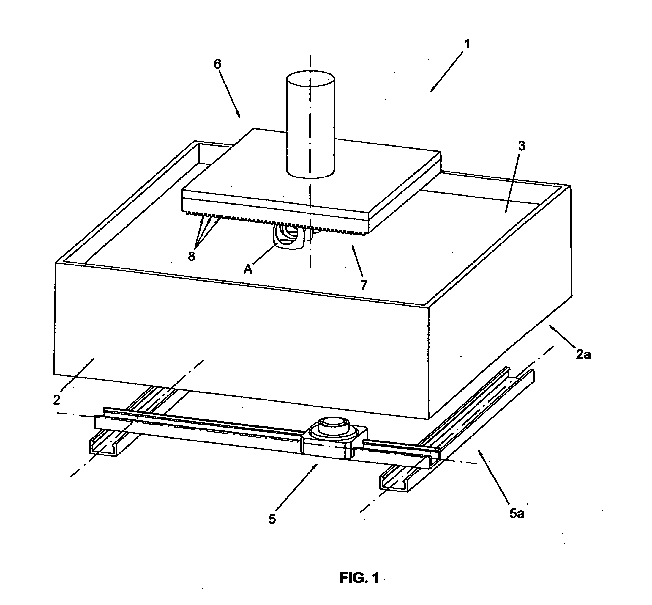
[0041] FIG. 1 shows an axonometric view of the stereolithography machine that is the subject of the invention;
[0042] FIG. 2 shows a side section view of the machine shown in FIG. 1;
[0043] FIG. 2a shows an enlarged detail of FIG. 2;
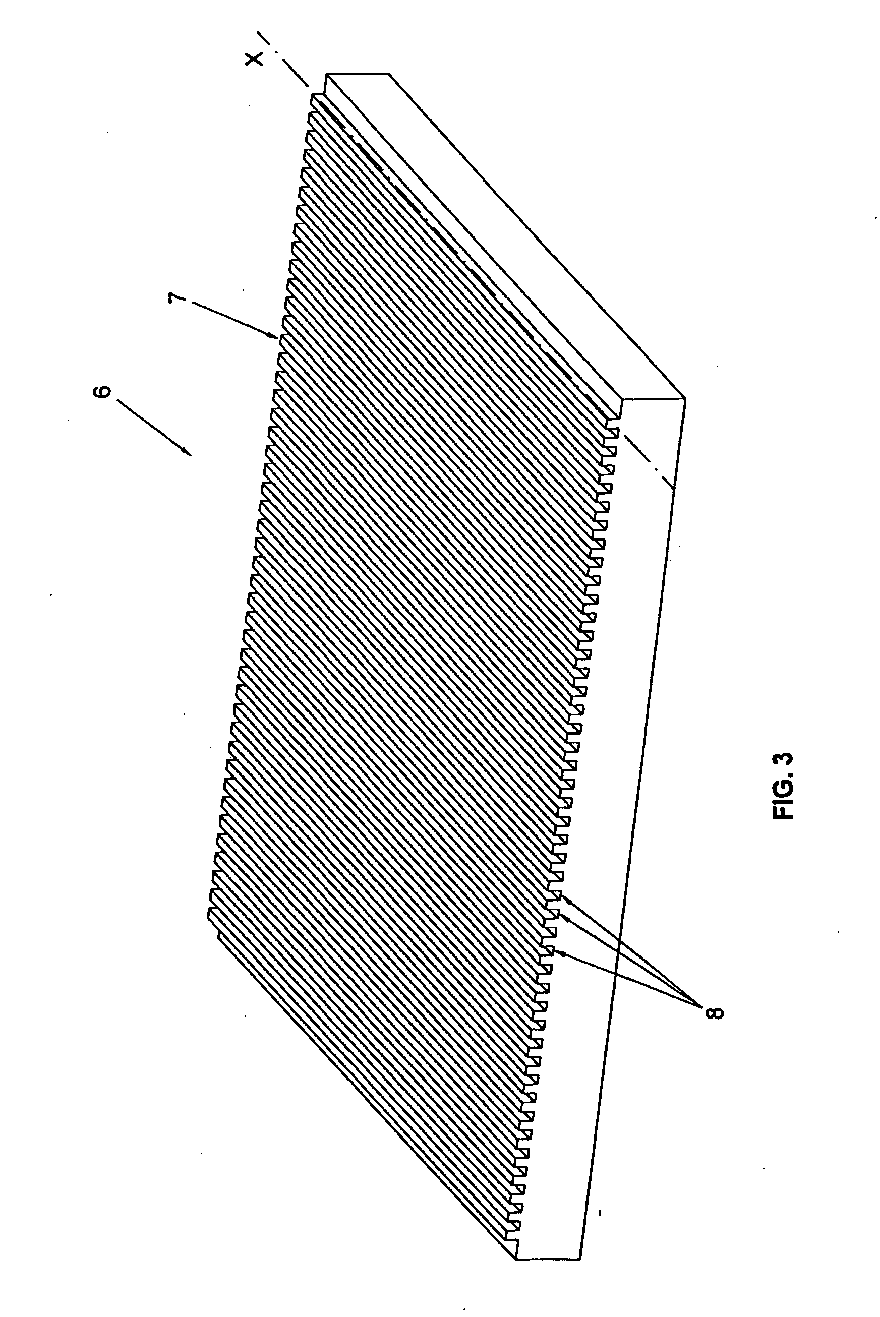
[0044] FIG. 3 shows an axonometric view of the modelling plate that is the subject of the invention;
[0045] FIG. 4 shows a side section view of a detail of the plate shown in FIG. 3;
[0046] FIGS. 4a and 4b show in detail a side section view of several variant embodiments of the plate shown in FIG. 4;
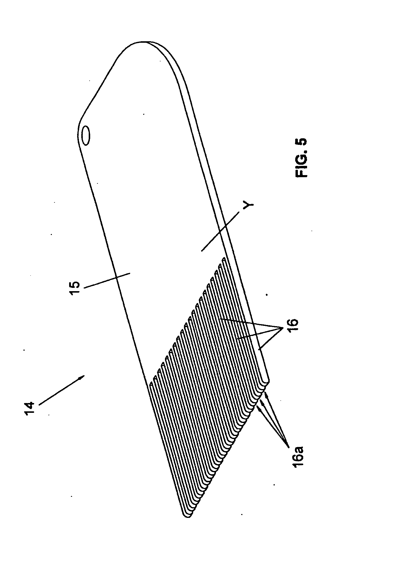
[0047] FIG. 5 shows an axonometric view of a tool for cleaning the plate of the invention;
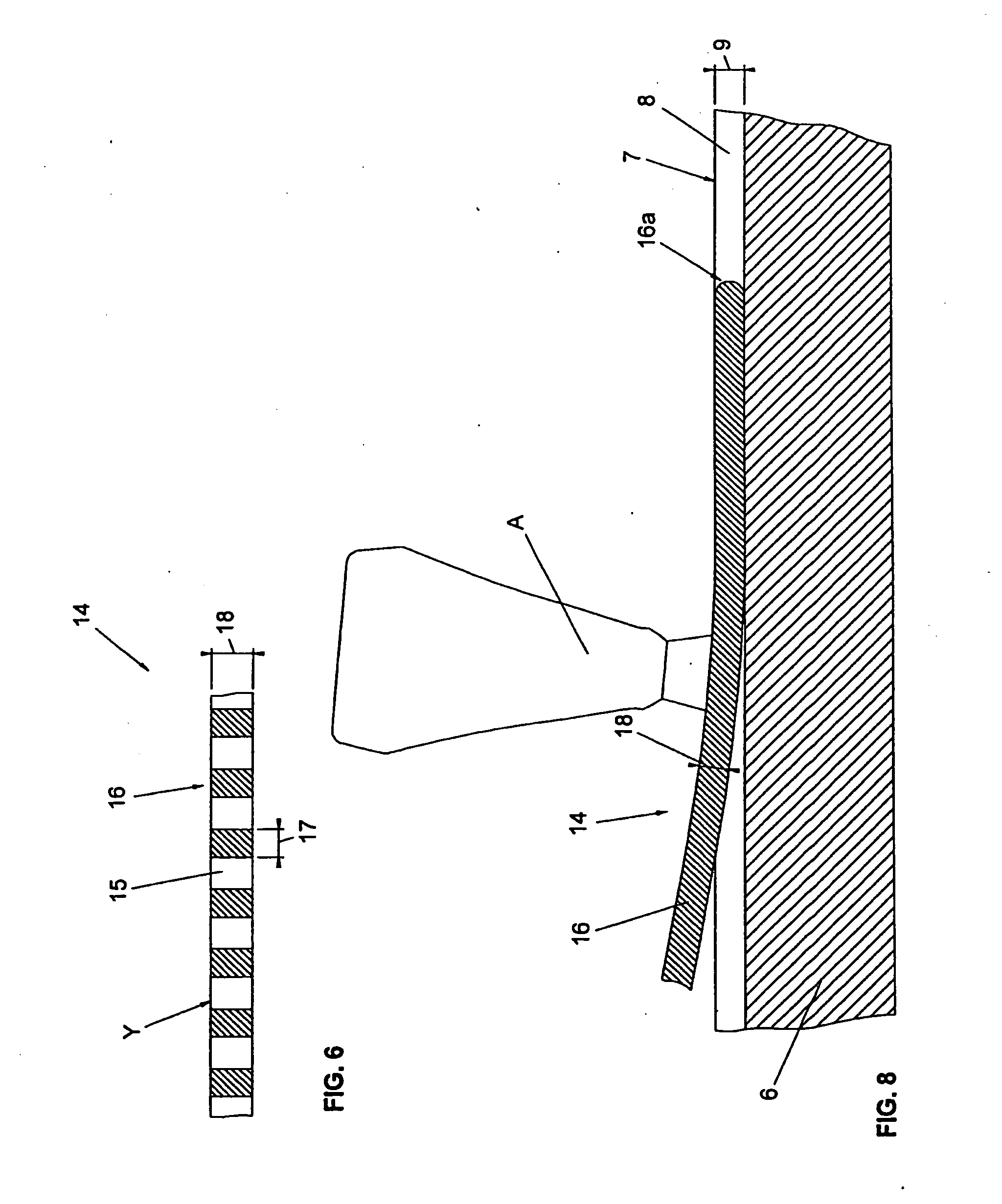
[0048] FIG. 6 shows a partial section view of the tool shown in FIG. 5;
[0049] FIG. 7 illustrates the use of the tool of FIG. 5 with the plate of FIG. 3;
[0050] FIG. 8 shows a side section view of a detail of FIG. 7.
[0051] As shown in FIG. 1, the stereolithography machine 1 of the invention comprises a tank 2 suited to contain a liquid substance 3 suited to solidify when subjected to a selective stimulation 4, shown in FIG. 2.
[0052] The above mentioned selective stimulation 4 is generated through emission means 5 that convey it towards the tank 2.
[0053] Preferably but not necessarily the liquid substance 3 is a light-sensitive resin and the emission means 5 comprise a laser emitter associated with scanner means 5a of any known type suited to direct the laser beam on the points of the layer of resin 3 to be solidified.
[0054] Obviously, variant embodiments of the invention may include other known types of emission means 5, provided that they can solidify the liquid substance 3.
[0055] The machine 1 also comprises a modelling plate 6, provided with a work surface 7 facing said emission means 5 and suited to support a three-dimensional object A being formed.
[0056] The machine 1 described above makes it possible to produce the three-dimensional object A by superimposing a plurality of layers E of said solidified resin 3 having a predefined thickness.
[0057] In particular, the first layers adhere to the work surface 7 of the plate 6, while the successive layers adhere to the previous ones.
[0058] Preferably but not necessarily the machine 1 is configured so as to form the object A under the modelling plate 6, as shown in FIGS. 1 and 2.
[0059] In particular, the emission means 5 are arranged under the tank 2 that has a bottom 2a that is transparent to stimulation 4.
[0060] Obviously, in this case, the plate 6 is arranged with the work surface 7 facing the bottom 2a of the tank 2.
[0061] According to a variant embodiment of the stereolithography machine of the invention, not shown herein, the emission means 5 are arranged over the tank 2.
[0062] In this second variant embodiment, the modelling plate 6 is arranged with the work surface 7 facing upwards and the three-dimensional object A is formed over the plate.
[0063] The plate 6 comprises a plurality of grooves 8 made in the work surface 7 along corresponding development trajectories parallel to one another and preferably rectilinear, as shown in FIG. 3.
[0064] During the formation of the first layers E of the object A adjacent to the work surface 7 of the plate 6, the resin 3' located in the grooves 8 is not reached by the stimulation 4 and, therefore, remains liquid, thus defining a corresponding number of channels interposed between the solidified object A and the plate 6, as shown in FIG. 2a.
[0065] At the end of the processing cycle, a corresponding elongated element 16 belonging to a cleaning tool 14, shown in FIG. 5, can be inserted and slided into each one of the above mentioned channels.
[0066] The elongated element 16 can exert a thrusting action on the three-dimensional object A in order to detach it from the work surface 7, as shown in FIG. 8.
[0067] Therefore, the above mentioned grooves 8 make it easier to detach the finished object A from the work surface 7, thus achieving one of the objects of the invention.
[0068] Advantageously, the above mentioned thrusting action poses fewer risks of damaging the object A than the known techniques, according to which the object A is removed using a sharp, tool.
[0069] Furthermore, advantageously, the tool A is not provided with a cutting edge and therefore cannot damage the plate 6.
[0070] Furthermore, as the object A is removed completely, it does not leave solid residues inside the grooves 8, thus achieving the further object to facilitate the cleaning of the plate 6.
[0071] The grooves 8 preferably extend to the perimeter edge of the work surface 7, opening up at the level of the lateral surface of the modelling plate 6, as clearly visible in FIG. 3.
[0072] It is clear that the above mentioned open end allows the resin 3 to flow from the grooves 8 towards the lateral area of the plate 6, and vice versa, during the vertical movement of the plate 6 itself.
[0073] Preferably, both ends of the grooves 8 are open at the level of the lateral surface of the plate 6, advantageously allowing the resin 3 to flow in both directions.
[0074] Therefore, if the plate 6 is arranged with the work surface 7 facing the bottom 2a of the tank 2, the resin 3 can flow along the grooves 8 from the centre of the plate 6 towards its sides, and vice versa.
[0075] Therefore, the invention achieves the object to facilitate the flow of the resin 3, especially when the plate 6 is arranged very near the bottom 2a of the tank 2.
[0076] Advantageously, the facilitated flow of the resin 3 makes it possible to reduce the pressure exerted on the bottom 2a of the tank 2 during the vertical movement of the plate 6.
[0077] Therefore, advantageously, it is possible to select movement speeds of the plate 6 that are equivalent to those possible, for example, with holed plates of known type, and in any case exceed those allowed by other known types of plate.
[0078] The grooves 8 preferably have depths 9 exceeding the thickness of the is layers E that make up the three-dimensional object A, for example in the order of tenths of a millimetre or more.
[0079] Advantageously, this makes it possible to prevent the first layers of the object A from clogging the grooves 8, if solidification occurs partly inside them due to processing needs or mispositioning of the plate 6.
[0080] The first case is the most common and derives from the fact that, to ensure the adhesion of the first layers E to the work surface 7 of the plate 6, a stimulation 4 is employed whose intensity is higher than the intensity strictly necessary to solidify the layer having predefined thickness.
[0081] The higher intensity of the stimulation causes a partial solidification of the resin 3' arranged inside the grooves 8, as shown in FIG. 2a.
[0082] The number of grooves 8, their width and their mutual distances on the plate 6 are parameters that can be selected by the manufacturer based on the operating characteristics of the machine 1 on which the plate 6 must be used.
[0083] In general, a more viscous resin 3 will require more grooves 8 in order to allow the optimal flow of the resin 3.
[0084] A higher number of grooves 8 also facilitates the removal of the object A from the plate 6.
[0085] On the other hand, a reduced number of grooves 8 increases the surface area of the work surface 7, thus improving the adhesion of the object A during processing.
[0086] By way of example, it has been found that grooves 8 approximately one millimetre wide arranged at a mutual distance of about one millimetre represent a good compromise in many circumstances.
[0087] It is evident, however, that in special cases it will be possible to use even one groove 8 only.
[0088] The grooves 8 preferably develop with a uniform cross section 11 along a rectilinear trajectory X.
[0089] In particular, and as shown in FIG. 4, the above mentioned cross section 11 is rectangular.
[0090] According to a variant embodiment of the plate of the invention, indicated in FIG. 4a by reference number 6', the cross section 11' has an area 12 whose width exceeds the width 10 of the same section at the level of the work surface 7.
[0091] In other words, the cross section 11' features an undercut surface that, advantageously, facilitates the adhesion of the three-dimensional object A to the groove 8 during the processing cycle.
[0092] The undercut is small enough not to hinder the removal of the finished three-dimensional object A from the plate 6.
[0093] Preferably but not necessarily the above mentioned cross section 11 has the shape of a trapezium, with the long base defining the bottom 2a of the groove 8 and the short base 10 corresponding to the opening of the groove 8 on the work surface 7.
[0094] According to a further variant embodiment, indicated in FIG. 4b by reference number 6'', the profile of the cross section 11'' features a recess 13 on one or both of the edges that delimit the cross section 11'' laterally.
[0095] Advantageously, said recess 13 further improves the adhesion of the three-dimensional object A to the plate 6 during the processing cycle. The depth of the above mentioned recess 13 is preferably limited to a few tenths of a millimetre, in such a way as not to hinder the successive removal of the object A.
[0096] It is obvious that other variant embodiments may have the characteristics of the previous two embodiments, combined together.
[0097] The cleaning tool 14 shown in FIG. 5 comprises a supporting body 15 from which one or more mutually parallel elongated elements 16 develop, each one of which is configured so as to slide inside a corresponding groove 8 of the plate 6.
[0098] The elongated elements 16 are arranged according to a reference plane Y and feature mutual distances that are the same as the mutual distances between the corresponding grooves 8.
[0099] The sliding of the elongated elements 16 inside the corresponding grooves 8 of the plate 6 makes it possible to exert a thrusting action on the three-dimensional object A that, advantageously, causes it to be removed from the work surface 7, as shown in FIGS. 7 and 8.
[0100] Preferably but not necessarily the tool 14 is provided with a number of elongated elements 16 equal to the number of grooves 8 of the plate 6, in such a way as to allow the removal of the three-dimensional object A with one pass only.
[0101] It is evident, however, that the tool 14 can be provided with any number of elongated elements 16, even lower than the number of grooves 8.
[0102] As shown in FIG. 6, the width 17 of each elongated element 16 with respect to a direction parallel to the reference plane Y is preferably uniform and substantially equal to the width of the corresponding groove 8 of the plate 6.
[0103] In this way, advantageously, each elongated element 16 has the maximum width compatible with the corresponding groove 8, thus allowing better distribution of the thrusting action on the three-dimensional object A.
[0104] The thickness 18 of the elongated elements 16 with respect to a direction orthogonal to the reference plane Y is preferably uniform along the direction of development of the elongated elements 16.
[0105] Furthermore, the thickness 18 preferably does not exceed the depth 9 of the corresponding groove 8, so as to advantageously make it possible to comfortably insert the elongated elements 16 between the three-dimensional object A and the plate 6.
[0106] It is also preferable that the thickness 18 of the elongated elements 16 be less than the depth 9 of the grooves 8, so as to facilitate the penetration of the elongated elements 16 even when the resin 3 solidifies partially inside the grooves 8, as described above.
[0107] According to a variant embodiment of the invention, not illustrated herein, the elongated elements 16 have increasing cross section from the end towards the supporting body 15, thus serving as wedges.
[0108] The elongated elements 16 preferably have rounded ends 16a that advantageously facilitate their insertion in the corresponding grooves 8, as shown in FIG. 8.
[0109] The elongated elements 16 are preferably made of a flexible material, in particular a plastic material, with the advantage of allowing a more gradual force to be exerted on the object A during removal from the plate 6, so as to reduce the risk of damaging it.
[0110] The elongated elements 16 in plastic material offer a further advantage lying in that their hardness is lower than the hardness of the materials commonly employed for the modelling plates, normally aluminium or other materials with similar hardness.
[0111] The reduced hardness of the elongated elements 16 prevents them from removing from the surface of the plate 6 some metal particles that may contaminate the resin 3 during the successive processing cycles, and also from damaging the plate 6.
[0112] The tool 14 can obviously be entirely made of a plastic material, with the advantage of reducing costs.
[0113] For this purpose the depth 9 of the grooves 8 should preferably exceed 0.5 mm, and preferably be in the order of 1 mm, so that the thickness of the tool 14 is compatible with the use of a plastic material.
[0114] It is also evident that, in variant embodiments of the invention, the tool 14 can be made of any material.
[0115] Obviously, the plate 6 and the tool 14 of the invention can be supplied in a kit intended to be used in a stereolithography machine 1, which incorporates the advantages of both components.
[0116] In practice, after the construction of the three-dimensional object A has been completed, it can be comfortably removed from the plate 6 without damaging it, using the cleaning tool 14.
[0117] In particular, the ends 16a of the elongated elements 16 are inserted in the corresponding grooves 8 of the plate 6 and are then slided along the grooves 8, as shown in FIG. 7.
[0118] During the sliding operation, the tool 14 is kept slightly inclined, so as to thrust the three-dimensional object A towards the outside of the plate 6 until it comes off.
[0119] Advantageously, as the three-dimensional object A is thrusted at the level of its base, it remains intact during separation from the plate 6, leaving no solid residue of resin 3 stuck in the grooves 8, as shown in FIG. 8.
[0120] Therefore, advantageously, the modelling plate 6 does not require further cleaning operations before being used for the production of a new three-dimensional object.
[0121] The above clearly shows that the modelling plate and the stereolithography machine of the invention achieve all the set objects.
[0122] In particular, the grooved modelling plate makes it particularly easy to remove the finished object from the plate itself, especially if using the tool of the invention.
[0123] The use of the tool of the invention ensures an almost perfect cleaning of the modelling plate.
[0124] Furthermore, the grooves of the plate facilitate the flow of the resin during the processing cycle, limiting the stress on the bottom of the tank and thus making it possible to increase the processing speed.
[0125] In any case, further variants of the invention, even if they are neither described herein nor illustrated in the drawings, must all be considered protected by the present patent, provided that they fall within the scope of the following claims.
[0126] Where technical features mentioned in any claim are followed by reference signs, those reference sings have been included for the sole purpose of increasing the intelligibility of the claims and accordingly such reference signs do not have any limiting effect on the protection of each element identified by way of example by such reference signs.
* * * * *
D00000
D00001
D00002
D00003
D00004
D00005
D00006
D00007
XML
uspto.report is an independent third-party trademark research tool that is not affiliated, endorsed, or sponsored by the United States Patent and Trademark Office (USPTO) or any other governmental organization. The information provided by uspto.report is based on publicly available data at the time of writing and is intended for informational purposes only.
While we strive to provide accurate and up-to-date information, we do not guarantee the accuracy, completeness, reliability, or suitability of the information displayed on this site. The use of this site is at your own risk. Any reliance you place on such information is therefore strictly at your own risk.
All official trademark data, including owner information, should be verified by visiting the official USPTO website at www.uspto.gov. This site is not intended to replace professional legal advice and should not be used as a substitute for consulting with a legal professional who is knowledgeable about trademark law.