Master Alloy Production For Glassy Aluminum-based Alloys
Watson; Thomas J.
U.S. patent application number 13/169202 was filed with the patent office on 2012-12-27 for master alloy production for glassy aluminum-based alloys. This patent application is currently assigned to UNITED TECHNOLOGIES CORPORATION. Invention is credited to Thomas J. Watson.
| Application Number | 20120328470 13/169202 |
| Document ID | / |
| Family ID | 46049248 |
| Filed Date | 2012-12-27 |
| United States Patent Application | 20120328470 |
| Kind Code | A1 |
| Watson; Thomas J. | December 27, 2012 |
MASTER ALLOY PRODUCTION FOR GLASSY ALUMINUM-BASED ALLOYS
Abstract
Apparatus is provided for forming aluminum alloy ingots in a sealed chamber having a source of inert gas using a crucible positioned inside the chamber for melting aluminum alloy powder. The crucible has a solid top and a source of inert gas therein. An outlet in the crucible is positioned to draw molten alloy from the crucible at a point proximate the lowest point in the crucible. A tundish adapted to control the flow of molten alloy from the crucible on a path to at least one ingot mold out of the sealed chamber
| Inventors: | Watson; Thomas J.; (South Windsor, CT) |
| Assignee: | UNITED TECHNOLOGIES
CORPORATION Hartford CT |
| Family ID: | 46049248 |
| Appl. No.: | 13/169202 |
| Filed: | June 27, 2011 |
| Current U.S. Class: | 420/528 ; 164/259; 164/68.1 |
| Current CPC Class: | C22C 21/00 20130101; F27B 14/04 20130101; C22C 45/08 20130101; B22D 21/04 20130101; F27B 14/10 20130101; B22D 21/007 20130101; B22D 7/005 20130101 |
| Class at Publication: | 420/528 ; 164/259; 164/68.1 |
| International Class: | C22C 21/00 20060101 C22C021/00; B22D 27/00 20060101 B22D027/00 |
Claims
1. Apparatus for forming aluminum alloy ingots, comprising: a sealed chamber having a source of inert gas; a crucible positioned inside the chamber for melting aluminum alloy input stock including, but not limited to, chips, shot, rod, bar, etc., the sealed chamber having a solid top and a source of inert gas therein adapted to drive out other atmosphere; an outlet in the crucible positioned to draw molten alloy from the crucible at a point proximate the lowest point in the crucible; and a tundish adapted to control the flow of molten alloy from the crucible on a path to at least one ingot mold while maintaining an inert atmosphere during the flow of alloy to the mold and out of the sealed chamber.
2. The apparatus of claim 1, wherein the outlet on the crucible is positioned to flow alloy out the bottom of the crucible.
3. The apparatus of claim 1, wherein the outlet on the crucible is positioned to flow alloy out of the lower side of the crucible.
4. The apparatus of claim 1, wherein the outlet includes a launder having, but not limited to, a cylindrical cross section for transferring the molten alloy from the crucible to the tundish.
5. The apparatus of claim 1, wherein the inert gas is argon.
6. The apparatus of claim 1, wherein the alloy is a devitrified glass-forming aluminum alloys having a nanometer-sized grain structure and nanometer-sized intermetallic phase or phases.
7. A method of forming aluminum alloy ingots, comprising the steps of: melting aluminum alloy feed stock in a crucible having an inert atmosphere; drawing molten alloy from the crucible at a point below the inert atmosphere; and maintaining an inert atmosphere during the flow of alloy from the crucible to a mold.
8. The method of claim 7, wherein the outlet of the crucible means is proximate the bottom of the crucible.
9. The method of claim 7, wherein the outlet of the crucible is positioned to flow alloy out of the lower side of the crucible.
10. The method of claim 7, wherein the the molten alloy is transferred from the crucible to the mold is performed with a launder having a cylindrical or other cross section.
11. The method of claim 7, wherein the inert gas is argon.
12. The method of claim 7, wherein the alloy is a devitrified glass-forming aluminum alloys having a nanometer-sized grain structure and nanometer-sized intermetallic phase or phases.
13. A method of forming aluminum alloy ingots, comprising the steps of: melting a quantity of aluminum alloy feed stock in a crucible, the crucible being positioned inside a chamber having an inert atmosphere at a pressure sufficient to drive out ambient atmosphere, the crucible melting the feed stock to a molten alloy; removing molten alloy from the crucible through an outlet at a point proximate the lowest point of the crucible; controlling the flow of molten alloy from the crucible to at least one ingot mold while maintaining an inert atmosphere, the flow being controlled with a tundish; and removing the at least one ingot mold from an inert atmosphere.
14. The method of claim 13, wherein the outlet means on the crucible means is positioned to flow alloy out the bottom of the crucible.
15. The method of claim 13, wherein the outlet means on the crucible means is positioned to flow alloy out of the lower side of the crucible.
16. The method of claim 13, wherein the outlet includes a launder having a cylindrical or other cross section for transferring the molten alloy from the crucible to the tundish.
17. The method of claim 13, wherein the inert gas is argon.
18. The method of claim 13, which further includes the step of maintaining the dew point in the crucible between -35.degree. F. (-37.2.degree. C.) and -110.degree. F. (-78.9.degree. C.) or lower.
19. The method of claim 13, wherein the alloy is a devitrified glass-forming aluminum alloy having a nanometer-sized grain structure and nanometer-sized intermetallic phase or phases.
20. An aluminum alloy formed by the method of claim 19.
Description
CROSS-REFERENCE TO RELATED APPLICATION(S)
[0001] This application is related to the following co-pending applications that are filed on even date herewith and are assigned to the same assignee: DIFFUSION BONDING OF GLASSY ALUMINUM-BASED ALLOYS, Ser. No. ______, Attorney Docket No. PA0009506U-U73.12-665; EXTRUSION OF GLASSY ALUMINUM-BASED ALLOYS, Ser. No. ______; Attorney Docket No. PA0009510U-U73.12-667KL; PRODUCTION OF ATOMIZED POWDER FOR GLASSY ALUMINUM-BASED ALLOYS, Ser. No. ______, Attorney Docket No. PA0009512U-U73.12-668KL; and FORGING OF GLASSY ALUMINUM-BASED ALLOYS, Ser. No. ______; Attorney Docket No. PA0009508U-U73.12-671KL. All referenced incorporated herein.
BACKGROUND
[0002] Aluminum alloys are important in many industries. Glassy Al-based alloys and their devitrified derivatives are currently being considered for applications in the aerospace industry. These alloys involve the addition of rare earth and transition metal elements. These alloys have high strength and, when processed appropriately, have high ductility.
[0003] One of the key requirements for high ductility is control of the uptake of hydrogen. While all Al-based alloys are sensitive to hydrogen, alloys containing rare earth elements are particularly susceptible to the effects of hydrogen during alloy production.
[0004] When Al-based alloys are produced in large quantities, they are often direct chill cast into molds that drop into well-like openings in the ground. For reactive materials such as Al--Li--X alloys, care must be exercised to preclude or prevent reaction of the Li with any oxidant such as air or water. For more reactive elements such as Yttrium and other rare earths, even more care is needed because exposure to water that is used to cool direct chill molds could result in fire and/or an explosion.
[0005] Al-based alloys such as Al--Y--Ni--Co alloys are devitrified glass-forming aluminum alloys that derive their strength from a nanometer-sized grain structure and nanometer-sized intermetallic phase or phases. The presence of hydrogen destroys the ductility of these alloys. Consequently, it is necessary to produce master alloys with hydrogen contents of 1 ppm or less. Examples of such alloys are disclosed in co-owned U.S. Pat. Nos. 6,974,510 and 7,413,621, the disclosures of which are incorporated herein by reference in their entirety.
[0006] It is necessary to find an alternative process for production of these highly reactive Al-based alloys.
SUMMARY
[0007] It has now been discovered that master alloy for devitrified glass-forming Al-based alloys can be produced in a process that avoids hydrogen pickup. The molten metal is isolated from the environment to a substantial degree. The process includes the use of a bottom-pour or side-pour crucible that is "covered" with an inert gas such as argon. The gas cover includes a physical cover on the top of the crucible into which argon or another inert gas such as nitrogen is bled into the crucible to form a positive pressure. The heavier argon forces out any air to minimize exposure of the melt to air.
[0008] The metal is poured out from the side or bottom of the crucible, rather than tipping to pour out the top. It is poured into a launder or pipe that is sealed and attached to the crucible, and is also filled with an inert gas such as argon. The molten metal flows through a launder or launder/tundish combination and is deposited directly into molds, which are also filled with inert gas such as argon.
BRIEF DESCRIPTION OF THE DRAWINGS
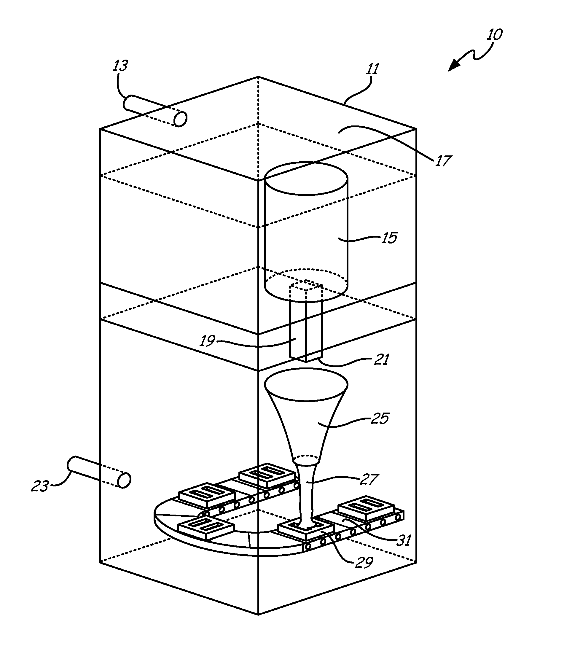
[0009] FIG. 1 shows one embodiment of a bottom pour furnace with a vertical feed for producing aluminum alloy ingots while avoiding hydrogen pickup.
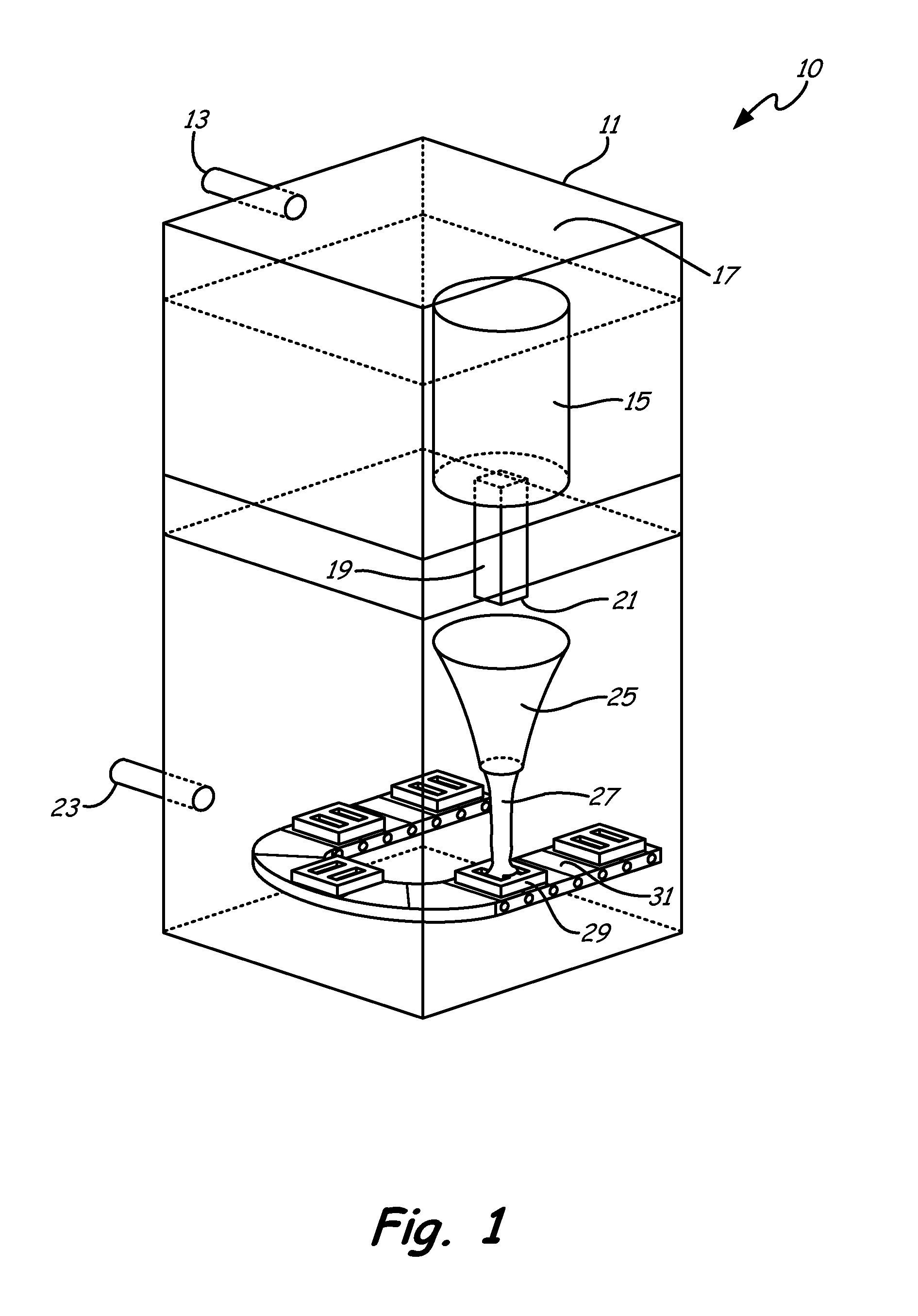
[0010] FIG. 2 shows another embodiment of a bottom pour furnace with a horizontal feed for producing aluminum alloy ingots while avoiding hydrogen pickup.
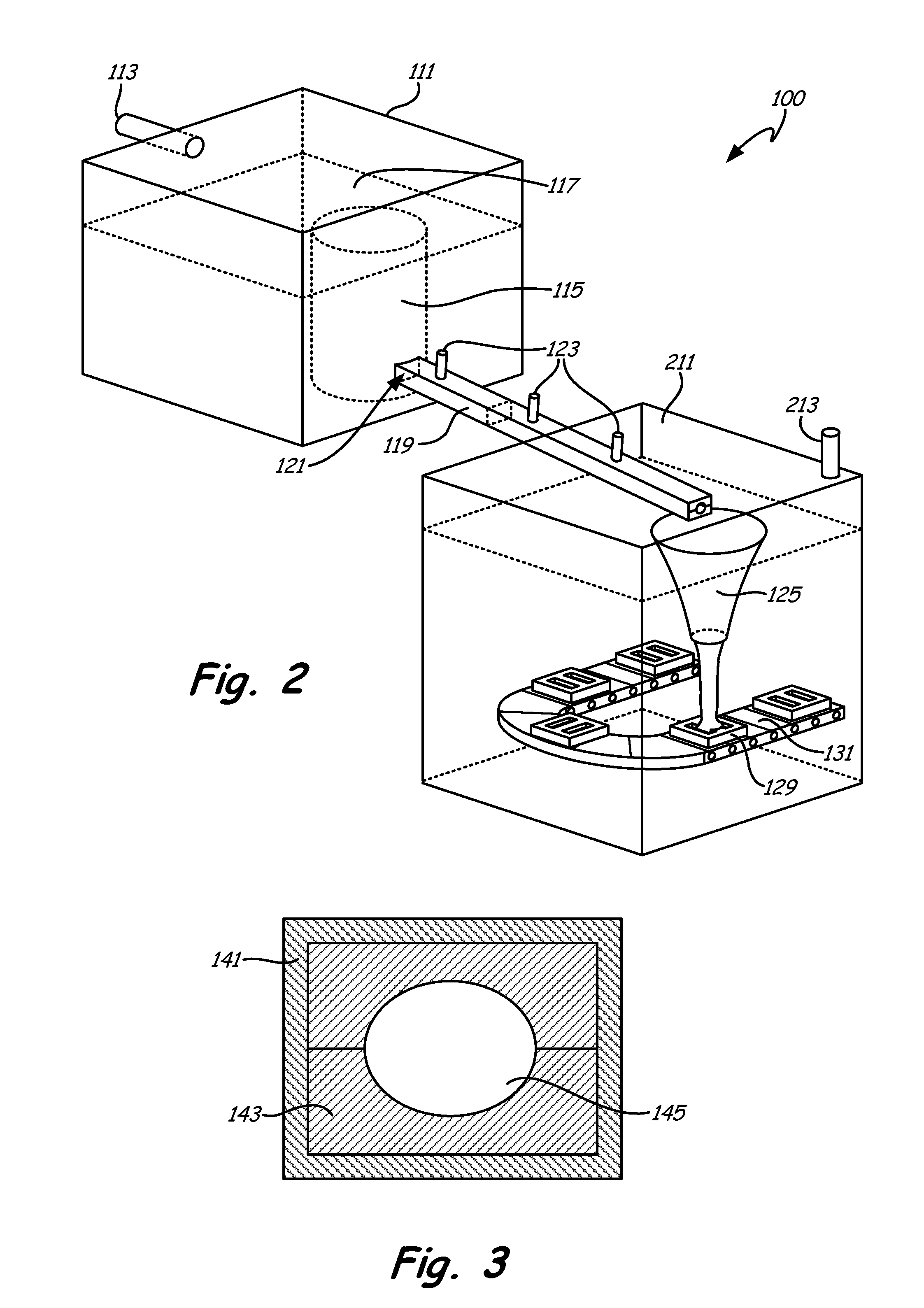
[0011] FIG. 3 is a possible cross section for the horizontal feed launders of the apparatus of FIG. 2.
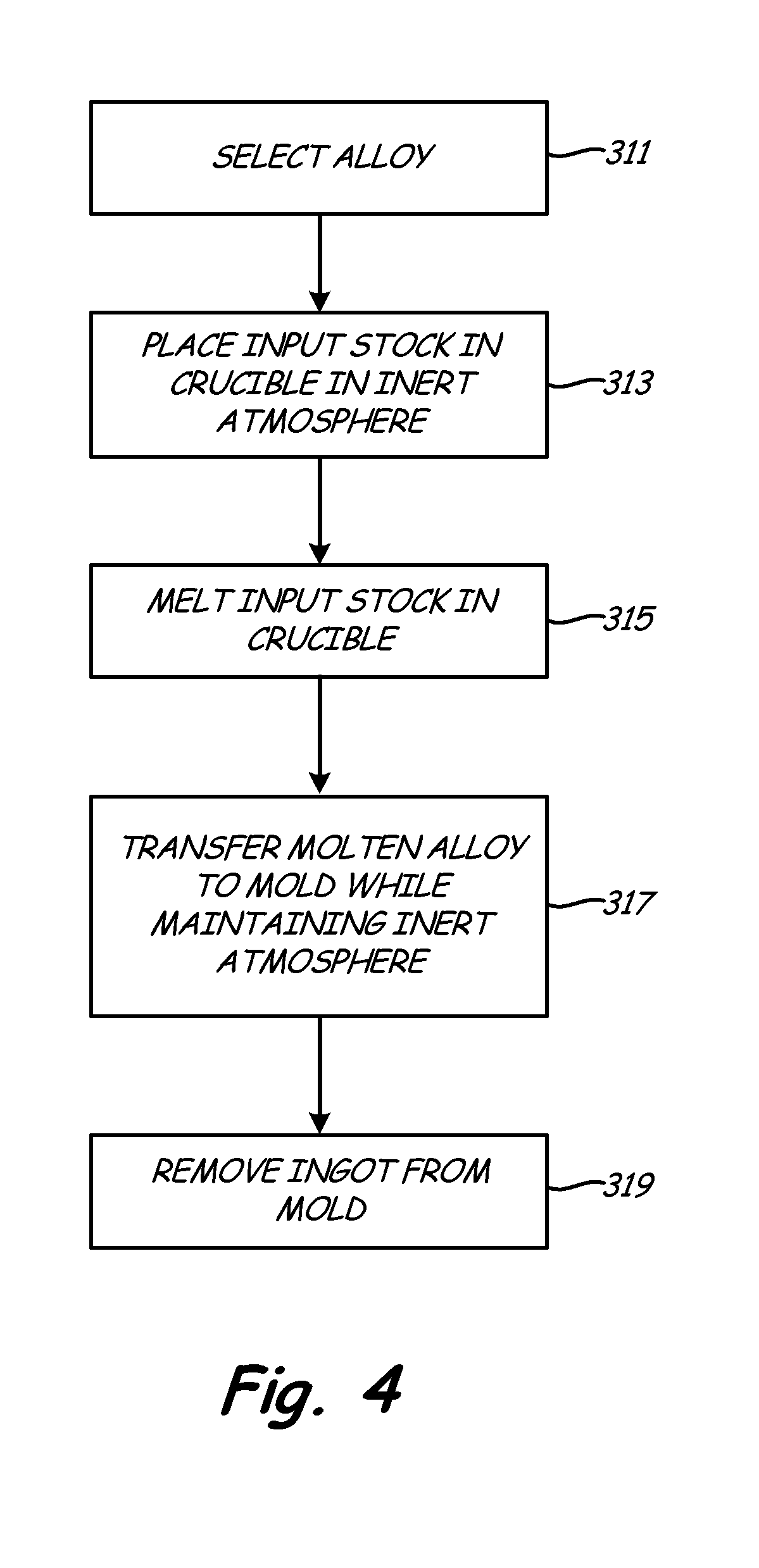
[0012] FIG. 4 is a flow diagram illustrating the method of forming aluminum master alloy ingots.
DETAILED DESCRIPTION
[0013] FIG. 1 illustrates a bottom pour furnace 10 generally with a vertical feed. The entire furnace is inside an inert chamber 11, having a solid top 17, with gas feed 13 introducing argon or another inert gas such as nitrogen. It is more effective if the inert gas is heavier than air, as argon is, to more easily push out any air that is initially present in chamber 11. A top-feed crucible 15 is located inside chamber 11. Inside crucible 15 is a quantity of aluminum and various alloy elements in the form of chips, shot, rod, etc. that is to be made into master alloy ingots. The aluminum alloy can be any alloy but it has been discovered that the glassy devitrified alloys such as those disclosed in co-owned U.S. Pat. Nos. 6,974,510 and 7,413,621, can be formed into low oxygen and low hydrogen master alloy ingots using the method of this invention.
[0014] The alloy in crucible 15 is purged with argon or another inert gas to drive out oxygen and any other reactive gas. Hydrogen from moisture is also driven out. Crucible 15 may be any low moisture/low volatiles alumina crucible, such as those produced by St. Gobain, or a graphite crucible with a spall-free alumina coating. Typical crucibles are ceramic cylinders that are about two feet in diameter and about three feet deep.
[0015] The alloy is melted in crucible 15 and exits the bottom of crucible through launder 19, so that the flow of molten alloy is controlled by position-control door 21. Launder may not be needed in some designs of crucible 15. With or without launder 19, the passage out of crucible 15 is also accomplished in an inert atmosphere via inert gas feed 23.
[0016] Tundish 25 is a funnel-shaped vessel into which the molten metal is poured. The purpose of a tundish is to allow the molten metal to reach a desired height (with a desired head pressure) so that there is a constant pour rate. It has been discovered that a slower rate precluded bubbles from forming in the melt. The height can be adjusted so there is no splashing of the metal into the molds. Flowing molten alloy 27 pours into waffle ingot molds 29 carried by conveyor belt 31, also in an inert atmosphere.
[0017] Allowing the molten alloy to drain down from the bottom of crucible 15 eliminates a major problem in prior art furnaces, in that the dross that accumulates on the top of the molten pool of alloy remains at the top and does not have to be removed until crucible 15 is cleaned prior to recharging with more alloy. Also, the dew point can be monitored, further preventing undesirable gas from contacting the sensitive elements of the alloy, thus preserving the low hydrogen/oxygen content of the master alloy.
[0018] For the two embodiments as discussed herein, a hygrometer with a computer can be used for measuring the amount of moisture, and therefore hydrogen, in the gases both at the source for 13 and 23, and within chamber 11 as a function of time. Best results are obtained when the dew point is -110.degree. F. (-78.9.degree. C.) or lower. A commercially available monitor such as an ALSCAN may be connected to a computer so that hydrogen readings in the melt may also be taken in real time. Similar readings in the launder can be used to monitor hydrogen there as well, which is to be as low as possible, i.e., less than 1 ppm.
[0019] In an alternative embodiment, a bottom pour furnace 100 generally is shown in FIG. 2. A first inert chamber 111, having a solid top 117, is maintained in an inert state via inert gas feed 113. Crucible 115 is filled or purged with an inert gas to drive out all reactive gasses, including hydrogen via the gas from 113. A launder 119, angled downward, is maintained with an inert atmosphere by a plurality of inert gas feeds 123 down stream of metal flow control door 121. Launder 119 has a typical cross section as shown in FIG. 3, with a steel or other hard casing 141, a ceramic mold or center passage 143 and the opening 145 through which the molten alloy flows. Tundish 125 controls the pour rate and pour height of molten alloy into waffle ingot molds 129 that are carried by conveyor belt 131. Again inert gas is maintained in second inert chamber 211 by inert gas feed 213.
[0020] FIG. 4 is a flow diagram of the method of this invention. Aluminum and the required elements in the form of chips, shot, rod, etc. (Step 311) are selected and placed in an enclosed crucible having an inert atmosphere (Step 313) with a positive pressure to drive out other gasses. The input stock is melted (Step 315) to form a molten alloy. The molten alloy is transferred (Step 317) to a mold while maintaining an inert atmosphere at least until the ingot is solidified. The ingot is then removed (Step 319) and available for subsequent processing.
[0021] Both bottom and side pouring embodiments have been found to be effective in producing satisfactory ingots. The advantage of the system of FIG. 1 is that the system is more compact with the launder going straight down. However, if the pouring goes too fast and can't be stopped, the risk of overpouring onto the floor exists. In the system of FIG. 2, more space is used but there can be multiple metal flow gates to contain failure at the bottom of the furnace.
[0022] While the invention has been described with reference to an exemplary embodiment(s), it will be understood by those skilled in the art that various changes may be made and equivalents may be substituted for elements thereof without departing from the scope of the invention. In addition, many modifications may be made to adapt a particular situation or material to the teachings of the invention without departing from the essential scope thereof. Therefore, it is intended that the invention not be limited to the particular embodiment(s) disclosed, but that the invention will include all embodiments falling within the scope of the appended claims.
* * * * *
D00000
D00001
D00002
D00003
XML
uspto.report is an independent third-party trademark research tool that is not affiliated, endorsed, or sponsored by the United States Patent and Trademark Office (USPTO) or any other governmental organization. The information provided by uspto.report is based on publicly available data at the time of writing and is intended for informational purposes only.
While we strive to provide accurate and up-to-date information, we do not guarantee the accuracy, completeness, reliability, or suitability of the information displayed on this site. The use of this site is at your own risk. Any reliance you place on such information is therefore strictly at your own risk.
All official trademark data, including owner information, should be verified by visiting the official USPTO website at www.uspto.gov. This site is not intended to replace professional legal advice and should not be used as a substitute for consulting with a legal professional who is knowledgeable about trademark law.