Apparatus And Methods For Optical Control Of Lighting Devices
Pickard; Paul Kenneth ; et al.
U.S. patent application number 13/169837 was filed with the patent office on 2012-12-27 for apparatus and methods for optical control of lighting devices. This patent application is currently assigned to Cree, Inc.. Invention is credited to Mike Harris, Paul Kenneth Pickard, Clinton Vilcans.
| Application Number | 20120328299 13/169837 |
| Document ID | / |
| Family ID | 47361959 |
| Filed Date | 2012-12-27 |


| United States Patent Application | 20120328299 |
| Kind Code | A1 |
| Pickard; Paul Kenneth ; et al. | December 27, 2012 |
APPARATUS AND METHODS FOR OPTICAL CONTROL OF LIGHTING DEVICES
Abstract
A lighting apparatus includes at least one light emitting device configured to receive an optical signal from a source external to the lighting apparatus and a control circuit coupled to the at least one light emitting device and configured to adjust a light output of the at least one light emitting device responsive to the received optical signal. The at least one light-emitting device may include at least one light-emitting diode (LED) configured to receive the optical signal, and the control circuit may include a detector circuit coupled to the at least one LED and configured to detect the received optical signal.
| Inventors: | Pickard; Paul Kenneth; (Morrisville, NC) ; Harris; Mike; (Cary, NC) ; Vilcans; Clinton; (Raleigh, NC) |
| Assignee: | Cree, Inc. |
| Family ID: | 47361959 |
| Appl. No.: | 13/169837 |
| Filed: | June 27, 2011 |
| Current U.S. Class: | 398/106 |
| Current CPC Class: | H04B 10/116 20130101; H05B 45/44 20200101; H05B 45/20 20200101 |
| Class at Publication: | 398/106 |
| International Class: | H04B 10/02 20060101 H04B010/02 |
Claims
1. A lighting apparatus comprising: at least one light emitting device configured to receive an optical signal from a source external to the lighting apparatus; and a control circuit coupled to the at least one light emitting device and configured to adjust a light output of the at least one light emitting device responsive to the received optical signal.
2. The apparatus of claim 1, wherein the at least one light-emitting device comprises at least one light-emitting diode (LED) configured to receive the optical signal, and wherein the control circuit comprises a detector circuit coupled to the at least one LED and configured to detect the received optical signal.
3. The apparatus of claim 1, wherein the at least one light-emitting device comprises at least one string of serially-connected LEDs configured to receive the optical signal and wherein the detector circuit is coupled to the string of serially-connected LEDs and configured to detect the received optical signal.
4. The apparatus of claim 3, wherein the at least one light-emitting device comprises a plurality of strings of LEDs of respective different colors and wherein the control circuit comprises respective string control circuits configured to control respective ones of the strings of LEDs responsive to the detector circuit.
5. The apparatus of claim 3, wherein the at least one light-emitting device comprises a string of LEDs of different colors.
6. The apparatus of claim 1, wherein the control circuit comprises a bypass circuit configured to variably conduct a bypass current around the at least one light-emitting device responsive to the received optical signal.
7. The apparatus of claim 1, wherein the control circuit is configured to adjust a lighting color and/or a lighting intensity produced by the apparatus responsive to the received optical signal.
8. The apparatus of claim 1, wherein the control circuit is configured to adjust a control input response of the at least one light-emitting device responsive to the received optical signal.
9. The apparatus of claim 8, wherein the control circuit is configured adjust a temperature response and/or a dimming response of the at least one light-emitting device responsive to the received optical signal.
10. The apparatus of claim 1, wherein the control circuit is further configured to inhibit further adjustment of the light output of the apparatus responsive to the received optical signal.
11. A lighting apparatus comprising: at least one light emitting device; and a control circuit coupled to the at least one light emitting device and configured to adjust a control input response of the at least one light emitting device responsive to an optical signal from a source external to the lighting apparatus.
12. The apparatus of claim 11, wherein the control circuit is configured to adjust a temperature response and/or a dimming response of the at least one light emitting device responsive to the optical signal.
13. The apparatus of claim 11, wherein the at least one light-emitting device comprises at least one light-emitting diode (LED) configured to receive the optical signal, and wherein the control circuit comprises a detector circuit coupled to the at least one LED and configured to detect the received optical signal.
14. The apparatus of claim 11, wherein the control circuit comprises a bypass circuit configured to variably conduct a bypass current around the at least one light-emitting device responsive to the received optical signal.
15. The apparatus of claim 11, wherein the control circuit is configured to adjust a lighting color and/or a lighting intensity produced by the apparatus responsive to the received optical signal.
16. The apparatus of claim 11, wherein the control circuit is configured adjust a temperature response and/or a dimming response of the at least one light-emitting device responsive to the received optical signal.
17. The apparatus of claim 11, wherein the control circuit is further configured to inhibit further adjustment of the control input response responsive to the received optical signal.
18. A lighting apparatus comprising: at least one light emitting device; and a control circuit coupled to the at least one light emitting device and configured to calibrate an operating characteristic of the at least one light emitting device responsive to an optical calibration signal from a source external to the lighting apparatus.
19. The apparatus of claim 18, wherein the control circuit is configured to adjust a control input response of the at least one light-emitting device responsive to the optical calibration signal.
20. The apparatus of claim 18, wherein the control circuit is configured to adjust a color and/or an intensity of light produced by the apparatus responsive to the optical calibration signal.
21. The apparatus of claim 18, wherein the at least one light-emitting device comprises at least one light-emitting diode (LED) configured to receive the optical signal, and wherein the control circuit comprises a detector circuit coupled to the at least one LED and configured to detect the received optical calibration signal.
22. The apparatus of claim 18, wherein the control circuit comprises a bypass circuit configured to variably conduct a bypass current around the at least one light-emitting device responsive to the received optical calibration signal.
23. The apparatus of claim 18, wherein the control circuit is further configured to inhibit adjustment of the control input response responsive to the received optical calibration signal.
24. A method of operating a lighting apparatus comprising at least one light emitting device, the method comprising: using the at least one light-emitting device to receive an optical signal from a source external to the lighting apparatus; and adjusting a light output of the at least one light emitting device responsive to the received optical signal.
25. The method of claim 24, wherein adjusting a light output of the at least one light emitting device responsive to the received optical signal comprises variably conducting a bypass current around the at least one light-emitting device responsive to the received optical signal.
26. The method of claim 24, wherein adjusting a light output of the at least one light emitting device responsive to the received optical signal comprises adjusting a lighting color and/or a lighting intensity produced by the apparatus responsive to the received optical signal.
27. The method of claim 24, wherein the control circuit is configured to comprises adjusting a control input response of the at least one light-emitting device responsive to the received optical signal.
28. The method of claim 24, further comprising inhibiting further adjustment of the light output of the apparatus responsive to the received optical signal.
29. A method of operating a lighting apparatus comprising at least one light emitting device, the method comprising: adjusting a control input response of the at least one light emitting device responsive to an optical signal from a source external to the lighting apparatus.
30. The method of claim 29, wherein adjusting a control input response of the at least one light emitting device responsive to an optical signal from an source external to the lighting apparatus comprises adjusting a temperature response and/or a dimming response of the at least one light emitting device responsive to the optical signal.
31. A method of operating a lighting apparatus comprising at least one light emitting device, the method comprising: calibrating an operating characteristic of the at least one light emitting device responsive to an optical calibration signal from a source external to the lighting apparatus.
32. The method of claim 31, wherein calibrating an operating characteristic of the at least one light emitting device responsive to an optical calibration signal from a source external to the lighting apparatus comprises adjusting a control input response of the at least one light-emitting device responsive to the optical calibration signal.
33. The method of claim 31, wherein calibrating an operating characteristic of the at least one light emitting device responsive to an optical calibration signal from a source external to the lighting apparatus comprises adjusting a color and/or an intensity of light produced by the apparatus responsive to the optical calibration signal.
34. The method of claim 31, wherein the at least one light-emitting device comprises at least one light-emitting diode (LED) configured to receive the optical signal, and wherein the method comprises receiving the optical calibration signal via the at least one LED.
35. The method of claim 31, further comprising inhibiting adjustment of the control input response responsive to the received optical calibration signal.
Description
FIELD OF THE INVENTION
[0001] The present invention relates to lighting devices and, more particularly, to apparatus and methods for control of lighting apparatus.
BACKGROUND
[0002] Solid state lighting arrays are used for a number of lighting applications. For example, solid state lighting panels including arrays of solid state light emitting devices have been used as direct illumination sources, for example, in architectural and/or accent lighting. A solid state light emitting device may include, for example, a packaged light emitting device including one or more light emitting diodes (LEDs). The LEDs may include, for example, inorganic LEDs that include semiconductor layers forming p-n junctions and/or organic LEDs (OLEDs) that include organic light emission layers.
[0003] In illumination applications, it is often desirable to calibrate a lighting source such that it produces a particular color and/or intensity. It may also be desirable to calibrate a lighting source to respond in a particular manner to environmental control inputs, such as temperature, and user control inputs, such as dimming inputs.
[0004] One technique to tune the color point of a lighting fixture is described in commonly assigned United States Patent Publication No. 2009/0160363, the disclosure of which is incorporated herein by reference. The '363 application describes a system in which phosphor converted LEDs and red LEDs are combined to provide white light. The ratio of the various mixed colors of the LEDs is set at the time of manufacture by measuring the output of the light and then adjusting string currents to reach a desired color point. The current levels that achieve the desired color point are then fixed for the particular lighting device.
[0005] Some conventional lighting devices are calibrated, for example, using test fixtures designed to communicate with control circuits in lighting devices. Such a test fixture may be connected to a lighting device under test using a connector or other mechanical access port, such as contact pads designed to be contacted by "pogo pins" or similar conductors. Accordingly, providing a calibration capability in a lighting device can be cumbersome and incur additional cost.
SUMMARY
[0006] Some embodiments provide a lighting apparatus including at least one light emitting device configured to receive an optical signal from a source external to the lighting apparatus and a control circuit coupled to the at least one light emitting device and configured to adjust a light output of the at least one light emitting device responsive to the received optical signal. The at least one light-emitting device may include at least one light-emitting diode (LED) configured to receive the optical signal, and the control circuit may include a detector circuit coupled to the at least one LED and configured to detect the received optical signal.
[0007] In some embodiments, the at least one light-emitting device may include at least one string of serially-connected LEDs configured to receive the optical signal, and the detector circuit may be coupled to the string of serially-connected LEDs and configured to detect the received optical signal. In some embodiments, the at least one light-emitting device may include a plurality of strings of LEDs of respective different colors and the control circuit may include respective string control circuits configured to control respective ones of the strings of LEDs responsive to the detector circuit. In some embodiments, the at least one light-emitting device may include a string of LEDs of different colors. In further embodiments, the control circuit may include a bypass circuit configured to variably conduct a bypass current around the at least one light-emitting device responsive to the received optical signal.
[0008] According to some embodiments, the control circuit may be configured to adjust a lighting color and/or a lighting intensity produced by the apparatus responsive to the received optical signal. In some embodiments, the control circuit may be configured to adjust a control input response of the at least one light-emitting device responsive to the received optical signal. The control circuit may be configured adjust a temperature response and/or a dimming response of the at least one light-emitting device responsive to the received optical signal. In further embodiments, the control circuit may be further configured to inhibit further adjustment of the light output of the apparatus responsive to the received optical signal.
[0009] Additional embodiments provide a lighting apparatus including at least one light emitting device and a control circuit coupled to the at least one light emitting device and configured to adjust a control input response of the at least one light emitting device responsive to an optical signal from a source external to the lighting apparatus. For example, the control circuit may be configured to adjust a temperature response and/or a dimming response of the at least one light emitting device responsive to the optical signal.
[0010] Further embodiments provide a lighting apparatus including at least one light emitting device and a control circuit coupled to the at least one light emitting device and configured to calibrate an operating characteristic of the at least one light emitting device responsive to an optical calibration signal from a source external to the lighting apparatus.
[0011] Some embodiments provide a method of operating a lighting apparatus including at least one light emitting device. The method includes using the at least one light-emitting device to receive an optical signal from a source external to the lighting apparatus and adjusting a light output of the at least one light emitting device responsive to the received optical signal.
[0012] Further embodiments provide a method that includes adjusting a control input response of the at least one light emitting device responsive to an optical signal from a source external to the lighting apparatus. Still further embodiments provide a method that includes calibrating an operating characteristic of the at least one light emitting device responsive to an optical calibration signal from a source external to the lighting apparatus.
BRIEF DESCRIPTION OF THE DRAWINGS
[0013] The accompanying drawings, which are included to provide a further understanding of the invention and are incorporated in and constitute a part of this application, illustrate certain embodiment(s) of the invention.
[0014] FIGS. 1A and 1B illustrate a solid state lighting apparatus in accordance with some embodiments of the inventive subject matter.
[0015] FIG. 2 is a schematic diagram illustrating a lighting apparatus with optical communications capability according to some embodiments of the inventive subject matter.
[0016] FIG. 3 is a schematic diagram illustrating an optically calibrated lighting apparatus including one or more strings of serially-connected LEDs according to some embodiments of the inventive subject matter.
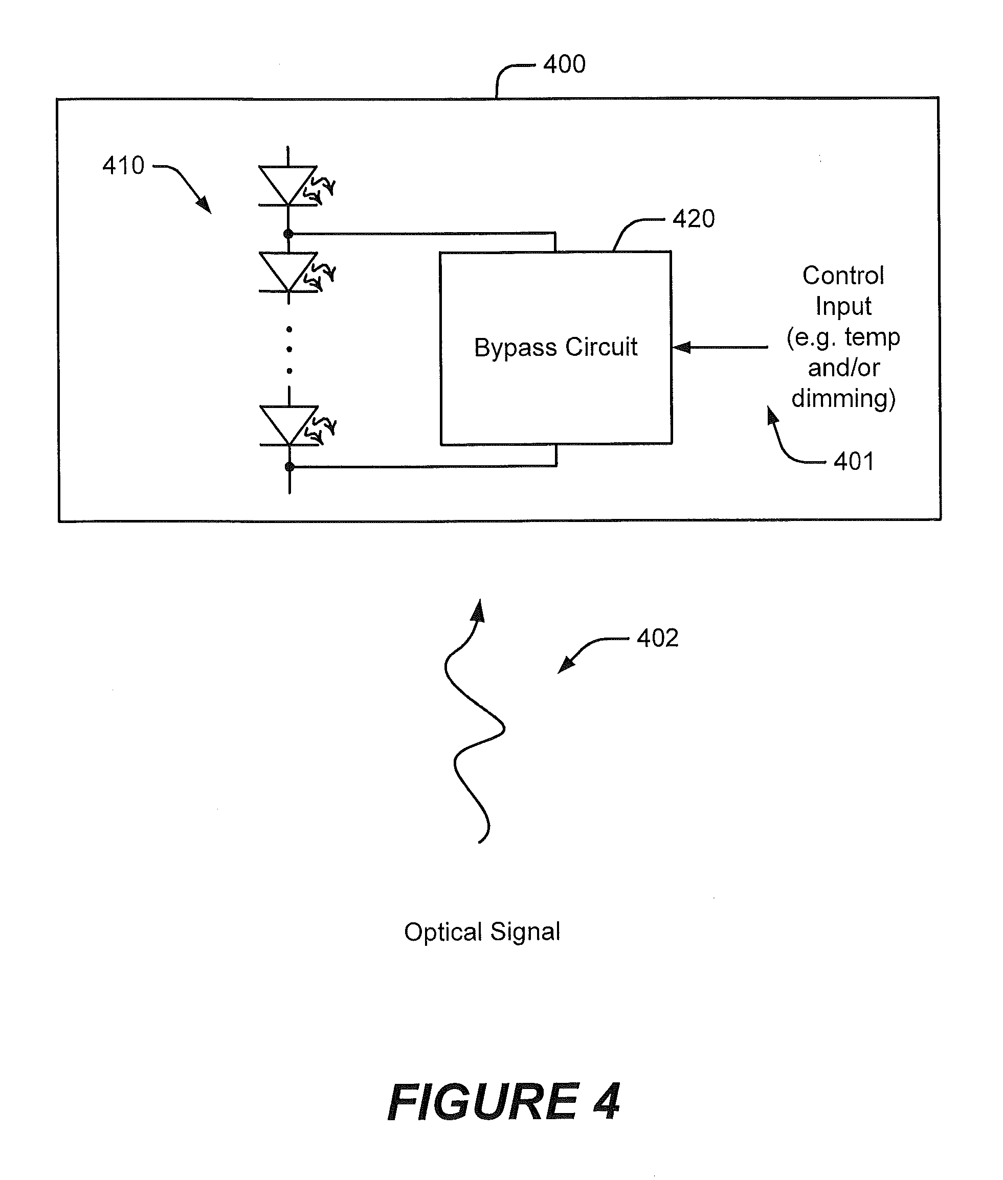
[0017] FIG. 4 is a schematic diagram illustrating an optically calibrated lighting apparatus with a controllable bypass circuit according to further embodiments of the inventive subject matter.
[0018] FIG. 5 is a schematic diagram illustrating a lighting apparatus configured to use an optically calibrated controllable bypass circuit for color point control according to some embodiments of the inventive subject matter.
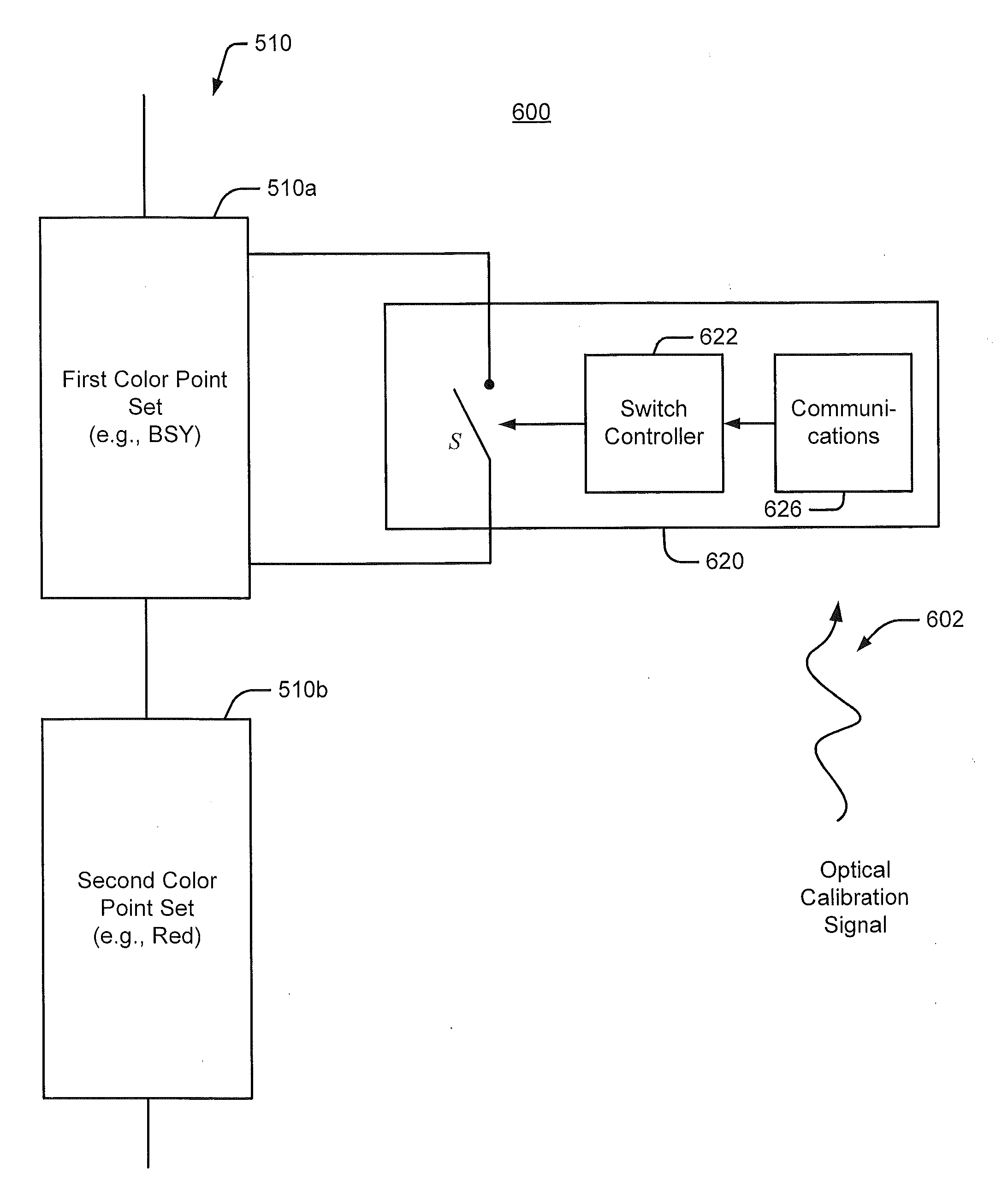
[0019] FIG. 6 is a schematic diagram illustrating a lighting apparatus with an optical communications circuit and a controllable bypass circuit for color point control according to further embodiments of the inventive subject matter.
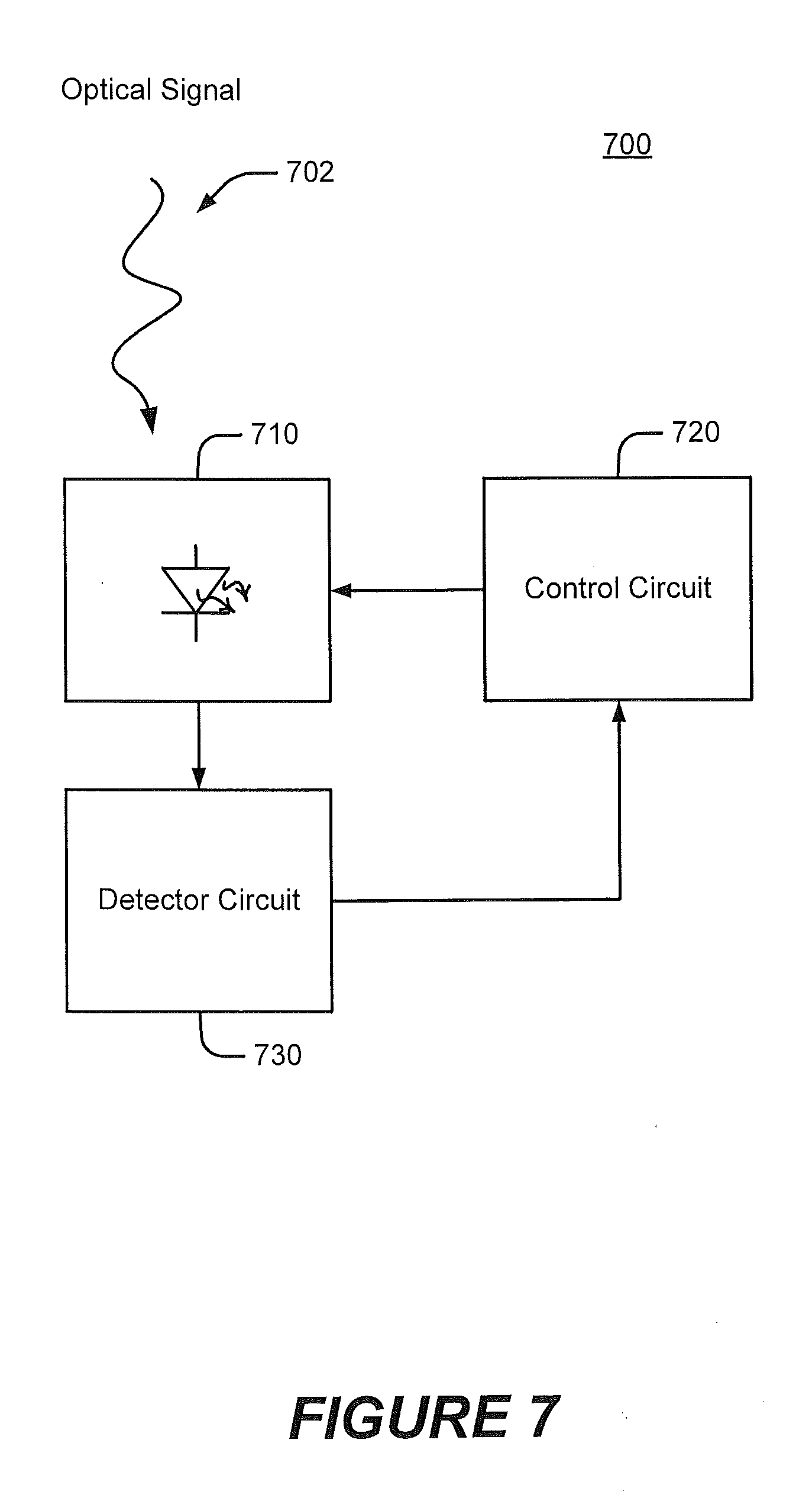
[0020] FIG. 7 is a schematic diagram illustrating a lighting apparatus using LEDs for illumination and communication according to some embodiments of the inventive subject matter.
[0021] FIG. 8 is a schematic diagram illustrating a lighting apparatus using LEDs for illumination and communication according to further embodiments of the inventive subject matter.
[0022] FIG. 9 is a schematic diagram illustrating apparatus and operations for calibrating a lighting apparatus according to some embodiments of the inventive subject matter.
DETAILED DESCRIPTION OF EMBODIMENTS
[0023] Embodiments of the present invention now will be described more fully hereinafter with reference to the accompanying drawings, in which embodiments of the invention are shown. This invention may, however, be embodied in many different forms and should not be construed as limited to the embodiments set forth herein. Rather, these embodiments are provided so that this disclosure will be thorough and complete, and will fully convey the scope of the invention to those skilled in the art. Like numbers refer to like elements throughout.
[0024] Embodiments of the present inventive subject matter now will be described more fully hereinafter with reference to the accompanying drawings, in which embodiments of the present inventive subject matter are shown. This present inventive subject matter may, however, be embodied in many different forms and should not be construed as limited to the embodiments set forth herein. Rather, these embodiments are provided so that this disclosure will be thorough and complete, and will fully convey the scope of the present inventive subject matter to those skilled in the art. Like numbers refer to like elements throughout.
[0025] It will be understood that, although the terms first, second, etc. may be used herein to describe various elements, these elements should not be limited by these terms. These terms are only used to distinguish one element from another. For example, a first element could be termed a second element, and, similarly, a second element could be termed a first element, without departing from the scope of the present inventive subject matter. As used herein, the term "and/or" includes any and all combinations of one or more of the associated listed items.
[0026] It will be understood that when an element is referred to as being "connected" or "coupled" to another element, it can be directly connected or coupled to the other element or intervening elements may be present. In contrast, when an element is referred to as being "directly connected" or "directly coupled" to another element, there are no intervening elements present.
[0027] The terminology used herein is for the purpose of describing particular embodiments only and is not intended to be limiting of the present inventive subject matter. As used herein, the singular forms "a", "an" and "the" are intended to include the plural forms as well, unless the context clearly indicates otherwise. It will be further understood that the terms "comprises" "comprising," "includes" and/or "including" when used herein, specify the presence of stated features, integers, steps, operations, elements, and/or components, but do not preclude the presence or addition of one or more other features, integers, steps, operations, elements, components, and/or groups thereof.
[0028] Unless otherwise defined, all terms (including technical and scientific terms) used herein have the same meaning as commonly understood by one of ordinary skill in the art to which this present inventive subject matter belongs. It will be further understood that terms used herein should be interpreted as having a meaning that is consistent with their meaning in the context of this specification and the relevant art and will not be interpreted in an idealized or overly formal sense unless expressly so defined herein. The term "plurality" is used herein to refer to two or more of the referenced item.
[0029] The following description of some embodiments of the inventive subject matter refers to "light-emitting devices," which may include, but is not limited to, solid-state lighting devices, such as light emitting diode (LED) devices. As used herein, "LED" includes, but is not limited to, direct-emission devices that produce light when a voltage is applied across a PN junction thereof, as well as combinations of such direct-emission devices with luminescent materials, such as phosphors that emit visible-light radiation when excited by a source of radiation, such as a direct-emission device.
[0030] Embodiments of the present invention provide systems and methods for controlling solid state lighting devices and lighting apparatus incorporating such systems and/or methods. In some embodiments, the present invention can be utilized in connection with bypass circuits as described in co-pending and commonly assigned U.S. patent application Ser. No. 12/566,195 entitled "Solid State Lighting Apparatus with Controllable Bypass Circuits and Methods of Operating Thereof" (Attorney Docket No. 5308-1128), co-pending and commonly assigned U.S. patent application Ser. No. 12/704,730 entitled "Solid State Lighting Apparatus with Compensation Bypass Circuits and Methods of Operation Thereof" (Attorney Docket No. 5308-11281P) and co-pending and commonly assigned U.S. patent application Ser. No. 12/566,142 entitled "Solid State Lighting Apparatus with Configurable Shunts" (Attorney Docket No. 5308-1091), the disclosures of which are incorporated herein by reference.
[0031] Referring to FIGS. 1A and 1B, a lighting apparatus 10 according to some embodiments is illustrated. The lighting apparatus 10 shown in FIGS. 1A and 1B is a "recessed downlight" or "can" lighting fixture that may be suitable for use in general illumination applications as a down light or spot light. However, it will be appreciated that a lighting apparatus according to some embodiments may have a different form factor. For example, a lighting apparatus according to some embodiments can have the shape of a conventional light bulb, a pan or tray light, an automotive headlamp, or any other suitable form.
[0032] The lighting apparatus 10 generally includes a can-shaped outer housing 12 in which a lighting panel 20 is arranged. In the embodiments illustrated in FIGS. 2A and 2B, the lighting panel 20 has a generally circular shape so as to fit within an interior of the cylindrical housing 12. Light is generated by solid state lighting devices (LEDs) 22, which are mounted on the lighting panel 20, and which are arranged to emit light 15 towards a diffusing lens 14 mounted at the end of the housing 12. Diffused light 17 is emitted through the lens 14. In some embodiments, the lens 14 may not diffuse the emitted light 15, but may redirect and/or focus the emitted light 15 in a desired near-field or far-field pattern. The LEDs 22 may include LEDs of different chromaticities that may be controlled to produce a desired intensity or color using various techniques discussed in detail below.
[0033] FIG. 2 illustrates a lighting apparatus 200 according to some embodiments. The apparatus 200 includes one or more light-emitting devices, here shown as one or more LEDs 210. The LEDs 210 are controlled by a control circuit 220, which may, for example, control an intensity and/or a color content of light produced by the one or more LEDs 210. As illustrated, the control circuit 220 may also control intensity, color and/or other characteristics responsive to one or more control inputs 201, such as temperature sensor inputs and/or dimming control inputs. The control circuit 220 may include, for example, analog circuitry, digital circuitry (e.g. a microprocessor or microcontroller) or a combination thereof.
[0034] As further shown, the apparatus 200 is further configured to receive an optical signal 202 and to adjust performance of the apparatus 200 responsive thereto. For example, in some embodiments, the optical signal 202 may be a calibration signal that causes the control circuit 220 to adjust a color point and/or intensity of light produced by the LEDs 210 responsive to the optical signal 202. In further embodiments, the optical signal 202 may be used to adjust a response of the control circuit 220 to the control input 201. For example, the optical signal 202 may be used to adjust a response to an environmental input, e.g., a temperature sensor signal, to provide a desired light output over a range of the environmental input. In some embodiments, the optical signal 202 may be used to adjust a response of the control circuit 220 to a user input, such as a dimming input, such that, for example, the lighting apparatus 200 provides a desired color temperature over a range of dimming control inputs.
[0035] In some embodiments, the apparatus 200 may include a dedicated optical receiver, such as an infrared (IR) receiver along the lines of the TSOP 36230 IR receiver produced by Vishay Intertechnology, may be used to receive the optical signal 202. According to further embodiments described below, the LEDs 210 themselves may serve as part of an optical receiver that receives the optical signal 202, such that the need for a special optical receiver may be eliminated.
[0036] In some embodiments, the apparatus 200 may be configured to be calibrated responsive to the optical signal 202. For example, during production testing and calibration of the apparatus 200, the optical signal 202 may be used to calibrate performance of the apparatus 200 without requiring special connectors. Parameters may be set at the factory using, for example, a modulated optical signal. Calibration may be completed by transmitting a "lock" code that inhibits further adjustment after the device is shipped.
[0037] An optical signal along the lines described above may be used to calibrate a variety of different types of lighting apparatus. For example, FIG. 3 illustrates a lighting apparatus 300 including one or more strings 310 of serially-connected LEDs. The one or more strings 310 of LEDs may be coupled to a current control circuit 320 that controls currents supplied to respective ones of the strings 310. As illustrated, the current control circuit 320 may act as a current source for the strings 310, but it will be appreciated that, in some embodiments, a current control circuit may operate as a controllable current sink for one or more strings of LEDs. The strings 310 may, for example, include LEDs of different colors, the output of which may be combined to produce an aggregate output with a white or other desired color. The current control circuit 320 may be configured to provide different currents to the respective strings to provide a desired output. As further illustrated, the current control circuit 320 may be calibrated or otherwise adjusted using an optical signal 302. For example, the optical signal 302 may be used to calibrate a color point of the apparatus 300 and/or to adjust a temperature response and/or a dimming response thereof.
[0038] As illustrated in FIG. 4, a lighting apparatus 400 according to further embodiments may include a string 410 of serially-connected LEDs and one or more bypass circuits 420 that are configured to bypass current around one or more of the LEDs in the string 410. Such a bypass circuit 420 may be controllable responsive to a control input, such as a temperature sense signal or a dimming signal along lines described, for example, in the aforementioned U.S. patent application Ser. No. 12/566,195 entitled "Solid State Lighting Apparatus with Controllable Bypass Circuits and Methods of Operating Thereof" (Attorney Docket No. 5308-1128) and U.S. patent application Ser. No. 12/704,730 entitled "Solid State Lighting Apparatus with Compensation Bypass Circuits and Methods of Operation Thereof" (Attorney Docket No. 5308-11281P). As further illustrated, operating characteristics of the bypass circuit 420 may be varied responsive to an optical signal 402.
[0039] For example, as illustrated in FIG. 5, a lighting apparatus 500 may include a string 510 of LEDs with one or more LEDs 510a having a first color point (e.g., blue-shifted yellow (BSY)) and one or more LEDs 510b having a second color point (e.g., red). A controllable bypass circuit 520 may selectively bypass current around the first LED's 510a responsive to a temperature signal such that, for example, the apparatus 500 produces a desired color over a range of temperatures. An optical signal 502 may be used to calibrate the bypass circuit 520 to provide a desired color behavior. FIG. 6 illustrates an exemplary implementation in which a bypass circuit 620 includes an optical communications circuit 626 that provides calibration information to a switch control circuit 622 that operates a bypass switch S. The calibration information may be provided responsive to an optical calibration signal 602.
[0040] According to further embodiments, an optical signal, such as an optical calibration signal, may be received by the same LEDs that are used to provide illumination in a lighting apparatus. Referring to FIG. 7, a lighting apparatus 700 may include one or more LEDs 710 that are configured to produce light under control of a control circuit 720. The apparatus 700 may include a detector circuit 730 coupled to the one or more LEDs 710. The detector circuit 730 may be configured to detect an optical signal 702 incident upon the LEDs 710. The detector circuit 730 may be coupled to the control circuit 720 and may convey calibration information in the optical signal 702 to the control circuit 720. In further embodiments, control information may be conveyed to the control circuit 720 in the same manner to implement functions other than calibration, such as to command certain behavior by the apparatus 700, such as, for example, a desired color, intensity or other effect. It will be appreciated that such dual use of LEDs for illumination and communication may be employed with a variety of different types of lighting circuits including, but not limited to, the configurations described above with reference to FIGS. 3-6.
[0041] FIG. 8 illustrates an example of a lighting apparatus 800 using LEDs for illumination and communication. A lighting apparatus 800 including a string 810 of serially-connected LEDs, coupled to a voltage source 840 and a current control circuit 850. The voltage source 840 may include, for example, a rectifier that is configured to be coupled to an AC line and that provides a DC output to the string 810. The current control circuit 850 may be, for example, a linear or switch mode power supply configured to control current passing through the string 810. The current control circuit 850 may be controlled by an LED control circuit 830, for example, a microprocessor-based circuit that provides drive signals to transistors or other current modulating devices in the current control circuit 850. Additional LED control circuitry, such as bypass circuitry, may also be present. For example, the optical signal 802 may be a pulsed signal, the modulation of which conveys calibration and/or other control information.
[0042] As further illustrated, the LED string 810 may be configured to receive an incident optical signal 802. The apparatus 800 may include an amplifier circuit 820 that is configured to detect the optical signal 802 by, for example, sensing a voltage across at least some of the LEDs of the string 810 that arise from currents generated by the incident optical signal 802. The optical signal 802 may be at a wavelength that differs from the wavelengths emitted by the LED string 810. The information in the detected signal may be used by the LED control circuit 830 for calibration or other purposes along the lines discussed above.
[0043] FIG. 9 illustrates operations and apparatus for calibrating a lighting apparatus 910 according to some embodiments. The lighting apparatus 910 includes one or more LEDs 912 and a control circuit 914 configured to control the LEDs 912. A test apparatus 920 includes a detector 924 configured to detect light produced by the lighting apparatus 910 to and to provide an output signal indicative of the detected light to a control processor 922. Responsive to this information, the control processor 822 may cause an optical transmitter 926 to generate an optical calibration signal, which may be received by the LEDs 912 or by a separate optical receiver in the lighting apparatus 910. The control circuit 914 may be configured to adjust the lighting apparatus 910 responsive to the optical calibration signal.
[0044] In the drawings and specification, there have been disclosed typical preferred embodiments of the invention and, although specific terms are employed, they are used in a generic and descriptive sense only and not for purposes of limitation, the scope of the invention being set forth in the following claims.
* * * * *
D00000
D00001
D00002
D00003
D00004
D00005
D00006
D00007
D00008
D00009
XML
uspto.report is an independent third-party trademark research tool that is not affiliated, endorsed, or sponsored by the United States Patent and Trademark Office (USPTO) or any other governmental organization. The information provided by uspto.report is based on publicly available data at the time of writing and is intended for informational purposes only.
While we strive to provide accurate and up-to-date information, we do not guarantee the accuracy, completeness, reliability, or suitability of the information displayed on this site. The use of this site is at your own risk. Any reliance you place on such information is therefore strictly at your own risk.
All official trademark data, including owner information, should be verified by visiting the official USPTO website at www.uspto.gov. This site is not intended to replace professional legal advice and should not be used as a substitute for consulting with a legal professional who is knowledgeable about trademark law.