Explosion Proof Forced Air Electric Heater
Dykman; Arjan
U.S. patent application number 13/164958 was filed with the patent office on 2012-12-27 for explosion proof forced air electric heater. Invention is credited to Arjan Dykman.
| Application Number | 20120328270 13/164958 |
| Document ID | / |
| Family ID | 47361943 |
| Filed Date | 2012-12-27 |

View All Diagrams
| United States Patent Application | 20120328270 |
| Kind Code | A1 |
| Dykman; Arjan | December 27, 2012 |
Explosion Proof Forced Air Electric Heater
Abstract
An explosion proof forced air electric heater is designed to supply heat to hazardous areas where the atmosphere contains readily combustible gases, vapors or dust particles. The heater employs an air mover which forces air through a metal heat sink with strategically placed electric heating elements. The terminal ends of the heating elements extend into a sealed and encapsulated explosion proof containment chamber which is connected to a centralized explosion proof enclosure. The explosion proof enclosure contains the control features and the electrical connections of the heater along with external accessories. The heating cycle is controlled via an electronic control circuit. The electronic circuit controls the process heating temperature, air mover operation, heating element operation, temperature measuring device operation, and monitors the total operation time of the heating elements while providing process failure feed back to the operator.
| Inventors: | Dykman; Arjan; (Airdrie, CA) |
| Family ID: | 47361943 |
| Appl. No.: | 13/164958 |
| Filed: | June 21, 2011 |
| Current U.S. Class: | 392/360 |
| Current CPC Class: | F24H 9/2071 20130101; H05B 1/0244 20130101; F24H 3/062 20130101; F24H 3/022 20130101 |
| Class at Publication: | 392/360 |
| International Class: | F24H 3/02 20060101 F24H003/02 |
Claims
1. An electric forced air heater particularly adapted to heat air in a hazardous area, comprising: a rectangular sheet metal housing; an electric motor driven axial air mover for moving air axially through said housing; at least one unit of heat transferring media embedded within said housing in a crosswise position, said media being formed of heat conducting metal tubes and fins having electric heat generating elements, an operating temperature monitoring device, and a predetermined high limit temperature monitoring device inserted therein; said heat transferring media having terminal extremities passing through a metal formed expandable conduit entering a metal formed centralized enclosure, said centralized enclosure housing internal and external controlling components; said electric motor having terminal extremities which pass through a metal formed expandable conduit entering a metal formed motor enclosure through a formed expandable conduit entering said centralized enclosure; a multitude of air deflectors positioned at the exiting point of said housing to direct exiting air.
2. A heat transfer media as claimed in claim 1 further comprising: a top and bottom header press fit on said metal tubes, said top and bottom header enclosed by header ends and covered with a header cover, forming an internal void, said internal void housing the electric heat generating element fastening terminals, with said fastening terminals connected via an electrical conducting device, said internal void is filled with an encapsulation compound, once cured, providing a protective hazardous area barrier.
3. Said encapsulation compound of claim 2 being of an electric resistant and heat conductive substance.
4. A heat transfer media as claimed in claim 2 that exhibits a cooler area in the center of said heat transfer media by applying a cooler heating source in the affected area within said electric heat generating elements.
5. An operating temperature monitoring device as claimed in claim 1 monitoring the operating temperature of said heat transferring media.
6. A predetermined high limit temperature monitoring device as claimed in claim 1 monitoring the predetermined high limit shutdown temperature of said heat transferring media.
7. Said centralized enclosure as claimed in claim 1 further comprising: an electronic control circuit comprised of a microcomputer controlling: pre programmed heating cycles, the monitoring and control of said electric motor, the monitoring and control of said electric heat generating elements, the monitoring of said operating temperature of said heat transferring media, the monitoring of said predetermined high limit temperature of said heat transferring media, the monitoring of the operating time of said electric heat generating elements, the monitoring of a predetermined high limit internal temperature, the triggering of safety mechanisms, and relaying of safety mechanism events; a solid state relay controlling said electric motor; a solid state relay controlling said electric heat generating elements; an electric motor current monitoring device monitoring the current of said electric motor; an electric heat generating element current monitoring device monitoring the current of said electric heat generating elements; an internal predetermined high limit temperature monitoring device, monitoring said predetermined high limit internal temperature of said centralized enclosure; an audible beeping device relaying said safety mechanism events; a visual illumination device relaying said safety mechanism events; a communications port communicating with said electronic control circuit; a thermostatic switch connection provision; an electric motor selecting switch selecting either an "auto on" or "continuous on" mode; an integral disconnect switch to disconnect power to all above said components.
8. The solid state relay of claim 7 can also be substituted for an electrical mechanical relay.
9. The communications port of claim 7 further comprising: communication between the end user and said electronic control circuit; communication between the end user and a world wide web interface; a computer interface for uploading heating cycle software and testing of said heating cycle software.
10. The preprogrammed heating cycles of claim 7 further comprising: a heating cycle wherein said electronic control circuit receives a demand for heat signal, momentarily switching said solid state relay and engaging said electric motor with said axial air mover to determine the working condition of said electric motor, by transferring a signal from said electric motor's current monitoring device to said electronic control circuit, wherein said electric motor is continuously monitored by said electric motor current monitoring device through transmission of a signal to said electronic control circuit; said electronic control circuit, which engages said electric heat generating elements within said heat transferring media by switching said solid state relay to start a preheat cycle, wherein said heat transferring media is continuously monitored by said electric heat generating element current monitoring device through transmission of a signal to said electronic control circuit; said operating temperature monitoring device which monitors the operating temperature of said electric heat generating elements within said heat transferring media until a predetermined preheat temperature, wherein said electric motor of said axial air mover is engaged by switching said solid state relay, forcing cool air though said electric heat generating elements within said heat media and pushing warm air into the atmosphere until the demand for heat has been met and said electronic control circuit disengages said solid state relay, which disengages the power running to said electric heat generating elements within said heat transferring media, allowing said electric motor to remain engaged and said axial air mover running until said heat transferring media has cooled to a predetermined set temperature, as monitored by said temperature monitoring device, completing said heating cycle.
11. Said heating cycle as claimed in claim 10 including an elevated ambient temperature scenario comprising: an oscillating cycle occurring during said elevated ambient temperature scenario which potentially triggers said heat transferring media to reach said predetermined high limit temperature and shutdown prior to reaching the demanded ambient temperature, wherein said electronic control circuit automatically triggers said oscillating cycle, where the heat transferring media temperature cycles between a predetermined upper and lower temperature limit, monitored by said operating temperature monitoring device until said demanded temperature has been met, completing said heating cycle.
12. The electronic control circuit of claim 7 wherein said safety mechanisms provide a safety shutdown of said electric forced air heater by disengaging the power leading to said electric motor and said electric heat generating elements, when triggered by an event comprising: an automatic shutdown when said electronic control circuit does not register a predetermined current from said electric motor current monitoring device prior to said preheat cycle of said heat transferring media due to failure of said electric motor, said current electric motor monitoring device, or said solid state relay; an automatic shutdown when said electronic control circuit does not register a predetermined current from said electric motor current monitoring device of said heat transferring media during said heat cycle due to failure of said electric motor, said electric motor current monitoring device, or said solid state relay; an automatic shut down when said electronic control circuit does not register a predetermined current from said heat generating element current monitoring device due to failure of said electric heat generating element, said heat generating element current monitoring device, or said solid state relay; an automatic shutdown when said electronic control circuit does not register a signal from said operating temperature monitoring device due to failure of said operating temperature monitoring device; an automatic shutdown when said electronic control circuit does not register a signal from said predetermined high limit safety temperature monitoring device due to failure of said predetermined high limit safety temperature monitoring device; an automatic shutdown when said electronic control circuit registers a signal from said predetermined high limit safety temperature monitoring device indicating said heat transferring media has reach said predetermined high limit temperature and is overheating; an automatic shutdown when said electronic control circuit does not register a signal from said predetermined internal high limit temperature monitoring device due to failure of said predetermined internal high limit safety temperature monitoring device; an automatic shutdown when said electronic control circuit registers a signal from said predetermined internal high limit safety temperature monitoring device indicating said centralized enclosure has reached said predetermined internal high limit temperature and is overheating.
13. The electronic control circuit of claim 7 wherein said safety mechanism elicits the relaying of an audible or visual signal to the operator by providing a predetermined sequenced beep from said beeping device, or a predetermined blinking sequence from said illumination device.
14. The electric motor selecting switch of claim 7 wherein the operating handle is mounted on the outside of said centralized enclosure and the switching gear is mounted on the inside of said centralized enclosure.
15. The electric motor selecting switch of claim 7 wherein said "auto on" selection signals said electric motor with said axial air mover to operate according to said preprogrammed heating cycles.
16. The electric motor selecting switch of claim 7 wherein said "continuous on" selection signals said electric motor with said axial air mover to operate continuously, strictly providing air movement as part of a cooling cycle.
17. The integral disconnect switch of claim 7 wherein the operating handle is mounted on the outside of said centralized enclosure and the switching gear is mounted on the inside of said centralized enclosure to form an isolated compartment of said centralized enclosure.
18. The motor enclosure of claim 1 further comprising an optional thermostatic switch housing.
19. The axial air mover of claim 1 wherein said axial air mover can be substituted with a centrifugal air mover.
20. The expandable conduit of claim 1 wherein said expandable conduit comprises: inner and outer cylindrical components which extend and retract telescopically on an axial plane, allowing for close tolerance fit.
Description
FIELD OF THE INVENTION
[0001] The present invention relates to an improved explosion proof forced air electric heater. The heaters are primarily used for heating hazardous environments where the incidences of fire or explosion are increased due to the presence of flammable gases, vapors, or liquids; combustible dust particles, filings, or ignitable fibers. Furthermore, the heaters can similarly be used to heat non-hazardous environments.
BACKGROUND OF THE INVENTION
Prior Art
[0002] Explosion proof forced air electric heaters have been on the market since the 1970's under U.S. Pat. No. 4,117,308. The majority of the forced air electric heaters currently in use rely upon a liquid filled heat exchanger. (See U.S. design Pat. D 356,367). These heat exchangers are generally comprised of three main components: (1) a steel bottom header; (2) steel tubes with roll formed aluminum fins; and (3) a steel top header, which houses a pressure relief valve. The bottom header contains the electric heating source, which is typically a tubular electric resistant element submerged in a glycol water mixture within the cavity of the bottom header. The prior art's heat transfer process is initiated by supplying the electric heating elements with electricity. The electricity is converted into heat, thereby increasing the temperature of the glycol water mixture to its boiling point, thus creating glycol steam, which rises through the steel tubes and into the top header. The heat is then conducted to the steel tubes and transferred to the roll formed aluminum fins where an air mover forces cool air over the fins to distribute the heat. The heating cycle is repeated when the glycol steam cools and reverts back to the bottom header in liquid form for reheating. The heat exchanger is typically vacuum charged to reduce the resistance exerted upon the glycol steam and to allow for even heat distribution during the cycle. The prior art's safety mechanisms include: the top header's pressure relief valve, which protects the heat exchanger in the event pressure limits are exceeded; and the high limit temperature switch imbedded in the bottom header, which cuts power to the electric heating elements and air mover should the system overheat.
[0003] The prior art is typically controlled by a thermostatic switch which monitors the ambient or desired environmental temperature. A call for heat typically activates a switch that engages a mechanical contactor, thereby triggering the electric heating elements and air mover simultaneously. Once the demanded temperature is achieved, the switch disengages the mechanical contactor and immediately turns off the electric heating elements and air mover.
[0004] The prior art's typical explosion proof forced air heaters have proven themselves reliable, however, the manner with which they transfer electric heat into the atmosphere and the lack of controllability thereof suggests several key short comings in the current design.
SUMMARY OF THE INVENTION
[0005] The present invention is designed to improve the performance and controllability of explosion proof forced air electric heaters.
[0006] The present invention is a liquid free dry heat exchanger. The dry heat exchanger is comprised of a top header and bottom header with heat transfer media coupled between the headers. The heat transfer media contains high heat conductive metal tubes with press fit high heat conductive metal fins. The heating source of the unit is assembled by embedding electric resistant heating elements within the metal tubes. The bottom and top headers are then press fit on either end of the metal tubes to form an electrical enclosure on either end of the heating elements.
[0007] The present invention is an electronically controlled heating system that makes use of an electronic circuit board to control and monitor the heating elements, air mover, operating temperature, internal enclosure temperature and high limit switch. The heating cycle begins when there is a demand for heat which engages a thermostatic switch, activating the circuit board. The circuit board then uses a solid state relay to momentarily engage the air mover to ensure it is in working condition before engaging the heat source. A current monitoring device assesses the air mover's functionality and sends a signal to the circuit board to either engage the heating elements if the air mover is operational, or terminate the startup cycle if the air mover is not working. Upon confirmation the air mover is operational, the circuit board switches a solid state relay to engage the electric heating elements. Once the elements heat the transfer media to a predetermined temperature, the circuit board re-engages the air mover and forces cool air over the heated fins and into the atmosphere. A temperature monitoring device implanted in the heat transfer media continuously monitors the media's temperature to ensure the air mover is not prematurely activated before the fins are sufficiently heated. The heating elements remain engaged until the demand for heat is met. Once met, the thermostatic switch disengages and signals the circuit board to disengage power from the heating elements. The air mover remains engaged until the heat transfer media has sufficiently cooled, at which time the temperature monitoring device sends a signal to the circuit board disengaging the air mover and completing the heating cycle. In the event the heater overheats, a high limit monitoring device positioned in the heat transfer media signals the circuit board to disconnect the heating elements and air mover simultaneously in order to safely shut the unit down. In contrast, the prior art typically uses mechanical relays to control the heater. Furthermore, the electrical heating elements and air mover are either engaged or disengaged simultaneously when there is a demand for heat or when the demanded temperature has been met.
[0008] The present invention heats the surrounding environment via two distinct heat transfer phases. Initially, the electric heating element is supplied with an electrical current which heats the heat transfer media that is comprised of alike metal tubes and fins. An air mover then transfers and distributes this heat from the tubes and fins into the surrounding environment by forcing cool air over the heating source. In comparison to the present invention's dual transfer theory, the prior art employs a less efficient design by requiring five distinct heat transfer phases to occur. The prior art initially transfers heat from (1) the electric heating elements to a glycol and water mixture. (2) As the mixture's temperature increases it is converted from a liquid into steam. (3) The steam's heat is then transferred to the steel tubes. Finally, (4) the steel tubes transfer their heat to the aluminum fins, at which time (5) the heat is distributed from the fins into the surrounding environment by an air mover.
[0009] During the present invention's heating cycle the heat transfer media increases in temperature proportionately to the ambient air's entering temperature. As a result, the ambient air could reach an elevated temperature where the heat transfer media risks reaching its high limit temperature before the demanded temperature has been met, triggering the high limit safety mechanism and initiating premature shutdown of the unit. To mitigate this scenario, the present invention's circuit board controls a cycling event whereby the heating elements are intermittently switched on and off at predetermined temperature ranges until the demanded temperature has been met, completing the heating cycle.
[0010] The electronic circuit board of the present invention has several fail safe safety mechanisms which will shut the heater down by disengaging the power to the elements and air mover. The scenarios that will elicit a safe shut down include but are not limited to the circuit board failing to register a predetermined current from the: air mover, heating elements, operating temperature monitoring device, internal enclosure high temperature limit, or the heat transfer high limit temperature switch. In the event the heat transfer media overheats, the high limit temperature monitoring device sends a signal to the electronic circuit board indicating the preset high limit temperature has been exceeded, forcing immediate shutdown. The prior art's failsafe safety mechanisms typically use a preset high limit temperature switch placed in series with the thermostat switch. As a result, the mechanical relay stays engaged until the high limit temperature switch disengages to remove power from the electric heating elements and the air mover. Certain systems have also provided a high ambient preset temperature device positioned in the centralized enclosure, but apart from the previously mentioned safety devices, no other form of safety shut down and/or monitoring features have been applied to the previous art.
[0011] The present invention also has an integral disconnect switch built directly into the centralized enclosure. This disconnect switch is an added safety feature which allows the heater to be fully disconnected from the power source for maintenance. Furthermore, the integral disconnect switch has been designed to allow for complete lock out, by means of a pad lock, during routine maintenance procedures. The previous art only provides this option on specialty models where a separate enclosure and added conduit is required, thereby increasing installation complexity and the total mass of the heating unit.
[0012] Further objects and advantages of the invention will become apparent from the following description read together with the accompanying drawings.
BRIEF DESCRIPTION OF THE DRAWINGS
[0013] For a better understanding of the present invention, aspects of the invention demonstrating the concepts of the present invention are illustrated, by way of example, in the enclosed Figures in which:
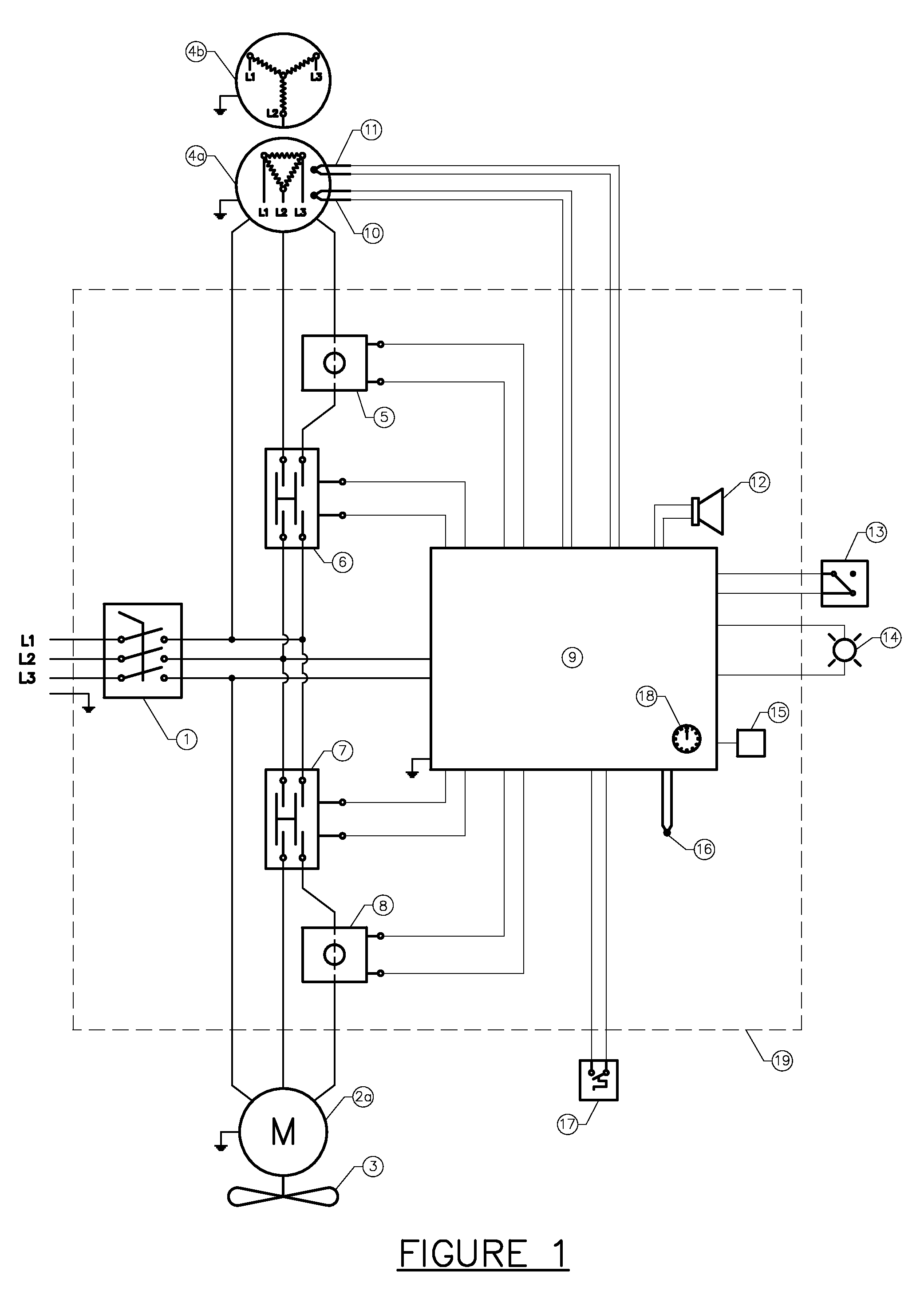
[0014] FIG. 1 is a schematic drawing showing a preferred three phase electronic control system of the present invention;
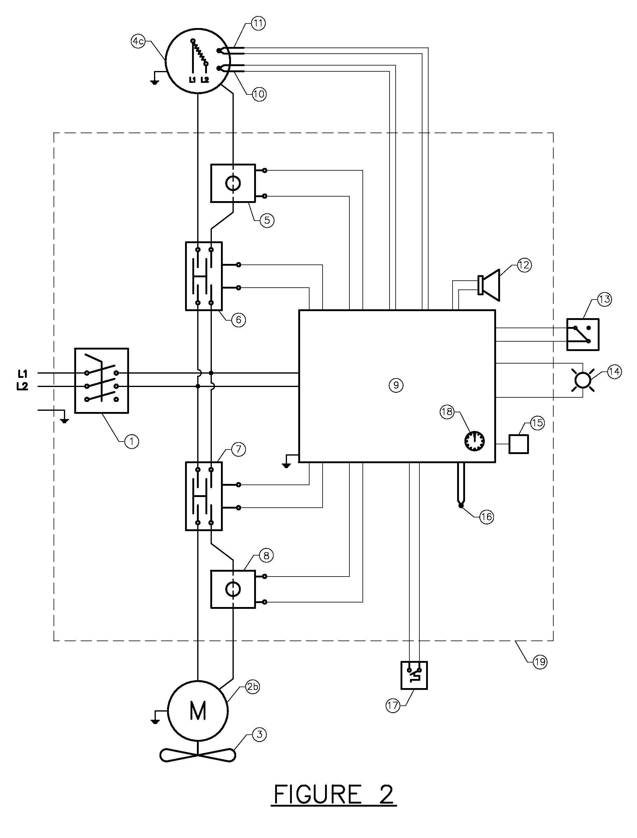
[0015] FIG. 2 is a schematic drawing showing a preferred single phase electronic control system of the present invention;
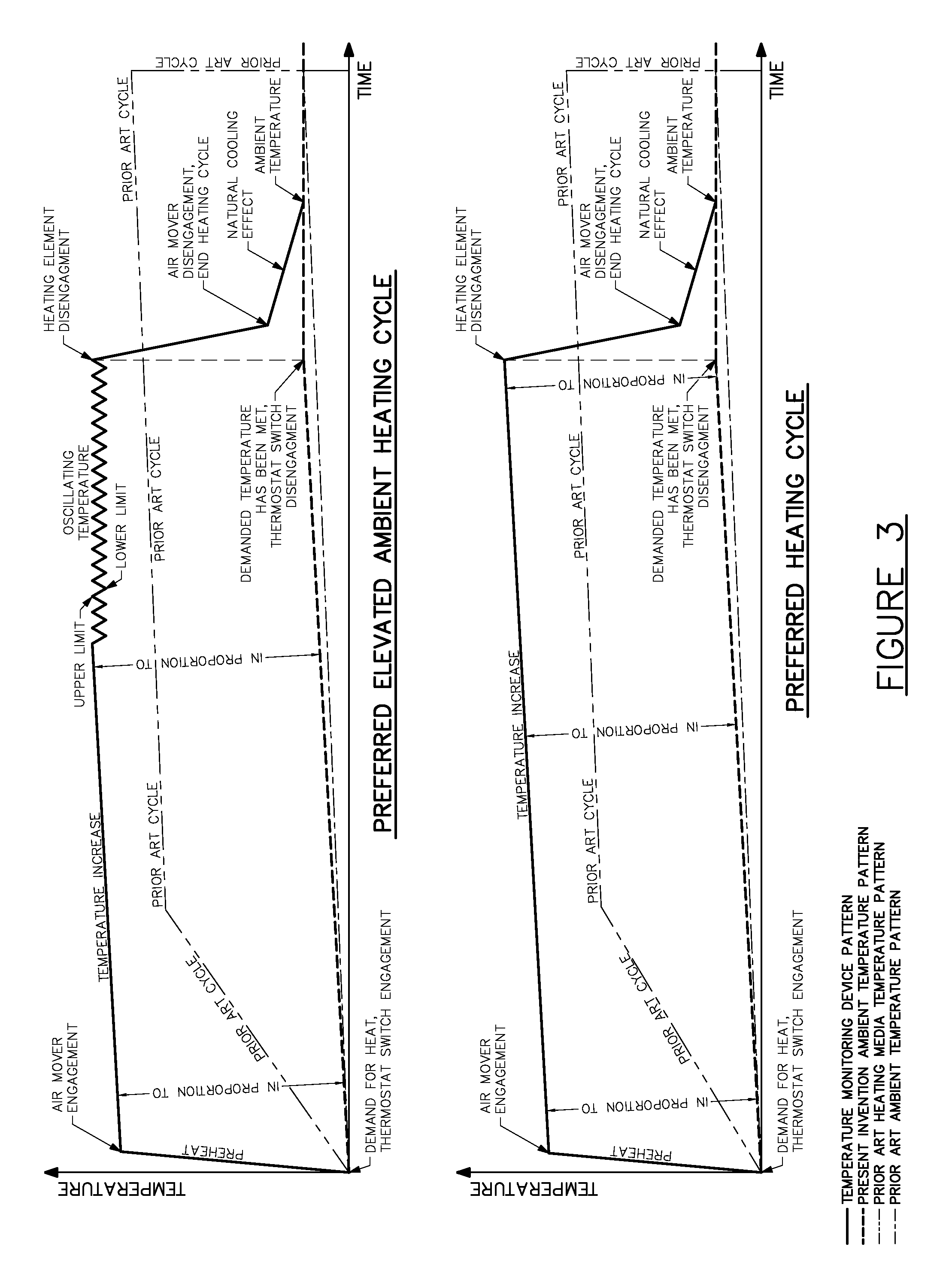
[0016] FIG. 3 illustrates a preferred heating cycle of the present invention in graphic format;
[0017] FIG. 4 is a front face view showing a preferred embodiment of the present invention;
[0018] FIG. 5 is a left hand side view thereof;
[0019] FIG. 6 is a right hand side view taken generally on line 6-6 of FIG. 4;
[0020] FIG. 7 is a rear side view taken generally on line 7-7 of FIG. 4;
[0021] FIG. 8 is a top view taken generally on line 8-8 of FIG. 4;
[0022] FIG. 9 is a perspective view from the front side of a preferred embodiment of the present invention;
[0023] FIG. 10 is a perspective view from the rear side of a preferred embodiment of the present invention;
[0024] FIG. 11 is an illustration of a preferred embodiment of the heat exchanger of the present invention.
[0025] FIG. 12 represents the front and side views from the prior art heat exchanger as per U.S. patent application D 356,367;
[0026] FIG. 13 is a cross-sectional view taken generally on line 13-13 of section A-A of FIG. 8 of the present invention and,
[0027] FIG. 14 is an illustration of a preferred alternate embodiment of the heat exchanger showing the front and side views of the present invention.
DESCRIPTION OF THE DRAWINGS AND OF THE PREFERRED EMBODIMENT
[0028] The present invention may be embodied in a number of different forms. The specifications and drawings that follow describe and disclose only some of the specific forms of the invention and are not intended to limit the scope of the invention as defined in the claims that follow herein.
[0029] With reference to FIGS. 1, 2 and 3, an explosion proof forced air electric heater according to the present invention operates in the following preferable operating sequence.
[0030] The typical heat cycle is preferably started by a thermostatic switch 17 enabling the electronic control circuit 9 to perform a preprogrammed heating cycle. The air mover 3 is preferably mounted to the electric motor 2a (three phase power), 2b (single phase power) and is engaged by switching a preferred solid state relay 7 momentarily to determine the working condition of the air mover, by transmitting a signal from a preferred current monitoring device 8 to the electronic control circuit 9. The electronic control circuit 9 engages the electric heating elements within the heat transfer media 4a (three phase delta power), 4b (three phase star power) or 4c (single power) by switching a preferred solid state relay 6. The electric heating elements within the heat transfer media 4a, 4b, 4c are continuously monitored preferably by a current monitoring device 5 that transmits a signal to the electronic control circuit 9. A preferred temperature sensing device 10 monitors the operating temperature of the electric heating elements within the heat transferring media 4a, 4b, 4c. The heat transfer media 4a, 4b, 4c will heat to a predetermined temperature and once the temperature has been met, the electric motor 2a, 2b is engaged by switching a solid state relay 7. Engagement of the electric motor 2a, 2b forces cooler air through the electric heating elements within the heat transfer media 4a, 4b, 4c and pushes warm air into the atmosphere. Once the demanded ambient temperature has been reached, the thermostatic switch 17 disengages, followed by the electronic control circuit 9 disengaging a solid state relay 6, which disengages the power leading to the electrical heating elements within the heat transfer media 4a, 4b, 4c. The electric motor 2a, 2b stays engaged and the air mover 3 operates until the heat transfer media 4a, 4b, 4c has cooled to a predetermined set temperature, as monitored by the temperature sensing device 10. The cooling of the heat transfer media completes the heating cycle and is illustrated in graphic format as per FIG. 3: "Preferred Heating Cycle". During the heat cycle, the electric motor 2a, 2b is continuously monitored by a preferred current monitoring device 8. The temperature monitoring device 11 is the high limit safety device which commands the electronic control circuit 9 to disengage power to the electric heating elements within the heat transfer media 4a, 4b, 4c and the electric motor 2a, 2b should the heat transfer media 4a, 4b, 4c overheat. In the event there is a demand for heat within an environment where the ambient temperature is already elevated, the heat transfer media 4a, 4b, 4c could potentially reach the high limit temperature and initiate a forced shutdown prior to reaching the demanded temperature. To avoid premature shutdown the electronic control circuit 9 automatically triggers an oscillating cycle, whereby, the heat transfer media 4a, 4b, 4c cycles between a predetermined upper and lower temperature limit, as monitored by the temperature monitoring device 10. The oscillating cycle continues until the demanded temperature has been met and the heating cycle is complete. This oscillating concept enables the heater to maintain maximum forced air output levels at all times within the capabilities of the present invention. The oscillating cycle described above is illustrated in graphic form by FIG. 3: "Preferred Elevated Ambient Heating Cycle," while the heating cycle of the prior art is similarly included for comparison purposes.
[0031] A two way switch 13 provides the option of controlling the electric motor 2a, 2b with an air mover 3 operating in either a preferred automatic selection mode or continuous selection mode. Under the automatic selection the electric motor 2a, 2b operates according to the preprogrammed heating cycle. Conversely, under the continuous selection mode the electric motor 2a, 2b runs continuously providing mere air movement as part of a cooling cycle.
[0032] The safety mechanisms within the preferred embodiment are illustrated, but not limited to, the following events illustrated below from a-h. Should either of these events occur, the power running to the electric heating elements within the heat transfer media 4a, 4b, 4c and the electric motor 2a, 2b will be disengaged and the heater will shutdown. All events will then preferably be relayed to the operator by providing a predetermined sequenced audible beep through device 12 or by the blinking of an illumination device 14.
[0033] a) If the electronic control circuit 9 is not registering a predetermined current from a current monitoring device 8 during the first warm up of the heat transfer media 4a, 4b, 4c due to failure of the: electric motor 2a, 2b; current monitoring device 8; or solid state relay 7, the heater will shutdown.
[0034] b) If the electronic control circuit 9 is not registering a predetermined current from the current monitoring device 8 during the normal heat cycle due to failure of the: electric motor 2a, 2b; current monitoring device 8; or solid state relay 7, the heater will shutdown.
[0035] c) If the electronic control circuit 9 is not registering a predetermined current from the current monitoring device 5 due to failure of the electric heating element within heat transfer media 4a, 4b, 4c; current monitoring device 5; or solid state relay 6, the heater will shutdown.
[0036] d) If the electronic control circuit 9 is not registering a signal from the operating temperature monitoring device 10 due to device failure, the heater will shutdown.
[0037] e) If the electronic control circuit 9 is not registering a signal from the high limit safety temperature monitoring device 11 due to device failure, the heater will shutdown.
[0038] f) If the electronic control circuit 9 registers a signal from the high limit safety temperature monitoring device 11 indicating the heat transfer media 4a, 4b, 4c has reached the predetermined high limit temperature and is overheating, the heater will shutdown.
[0039] g) If the electronic control circuit 9 is not registering a signal from the enclosure high ambient temperature monitoring device 16 due to device failure, the heater will shutdown.
[0040] h) If the electronic control circuit 9 registers a signal from the enclosure's high ambient safety temperature monitoring device 16 indicating the flame proof enclosure 19 has reached the predetermined high ambient safety temperature and is overheating, the heater will shutdown.
[0041] Communication port 15 provides an interface between the operator and electric control circuit.
[0042] A preferred built-in time monitoring device 18 provides feedback for the operator pertaining to the amount of time the electrical heating elements within the heat transfer media 4a, 4b, 4c have been engaged.
[0043] In order to safely perform maintenance on the preferred embodiment of the present invention, an integral disconnect switch 1 can be disconnected to eliminate power to all of the above described items. This switch also functions as a reset device through its disconnection and re-connection of power to the electronic circuit board 9, thereby clearing the safety event.
[0044] A flame proof enclosure 19 houses the spark causing devices.
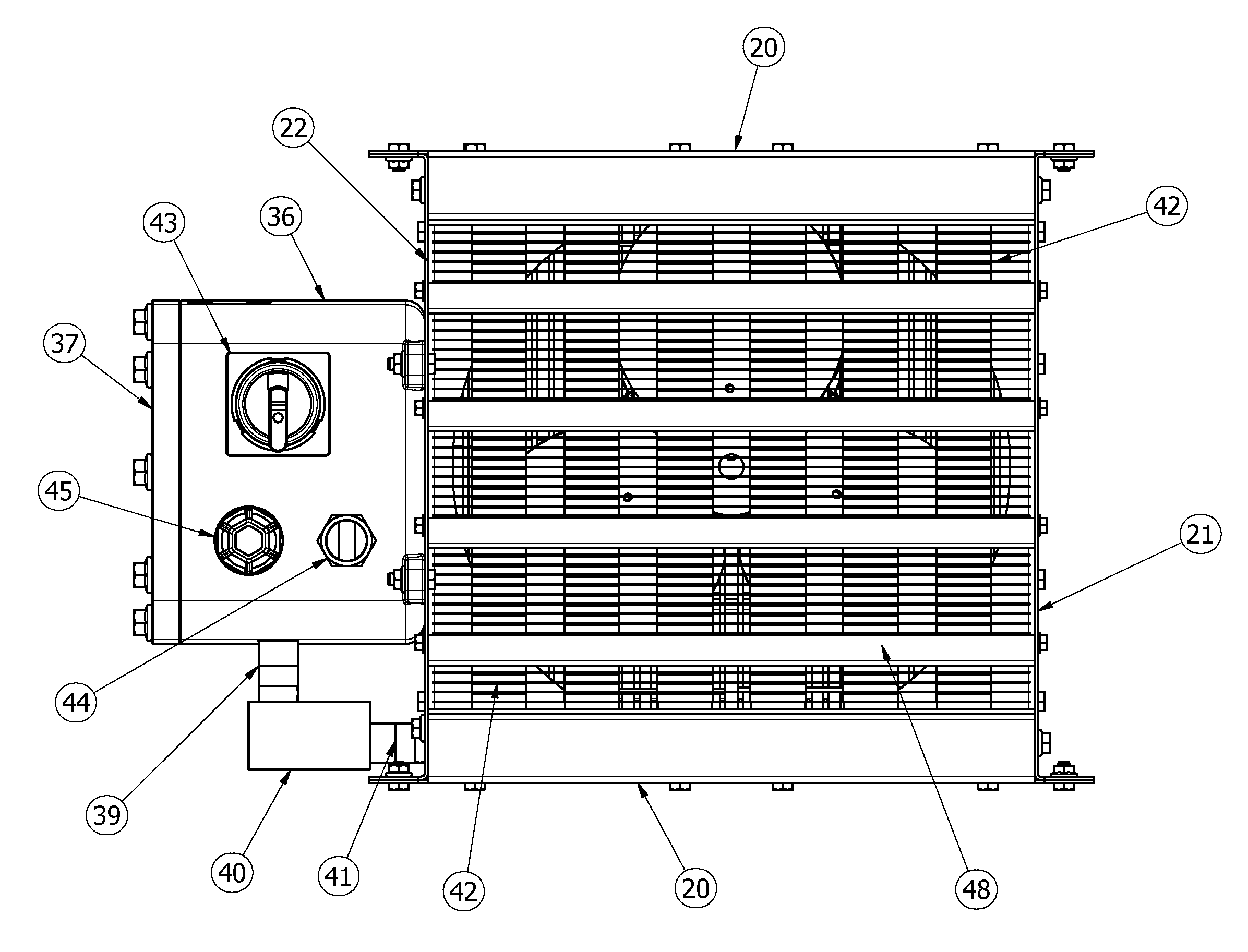
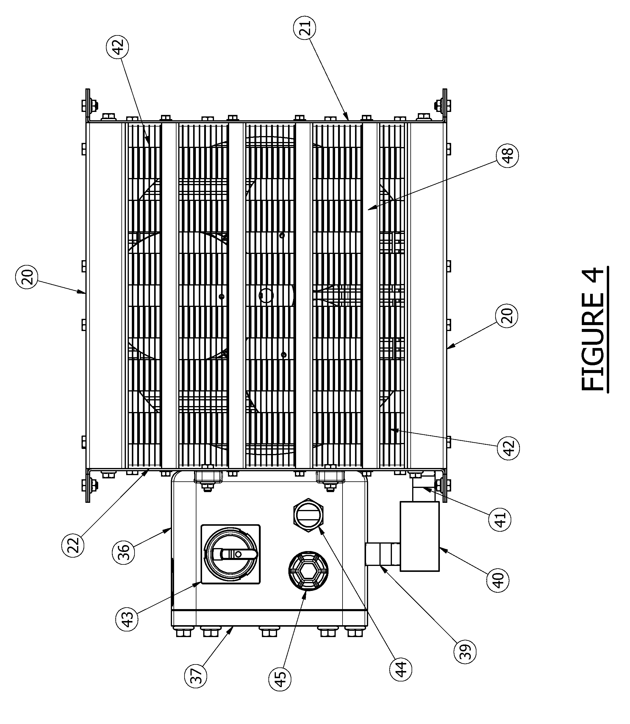
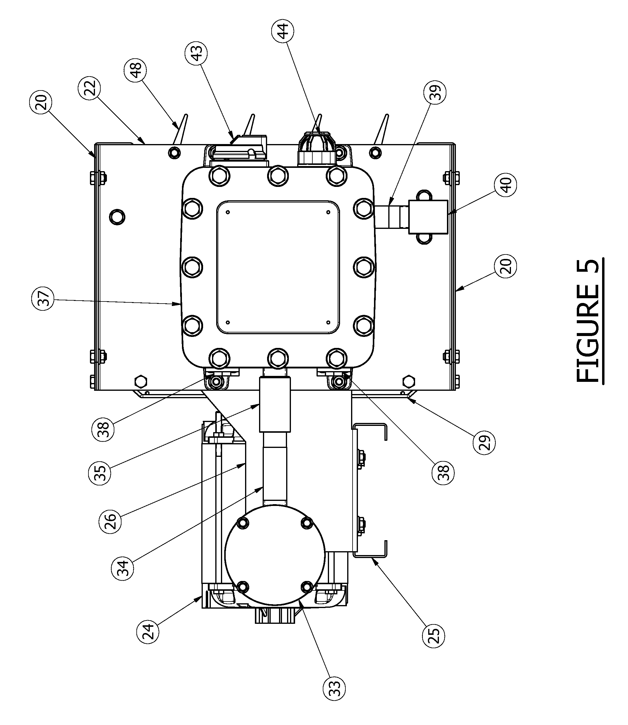
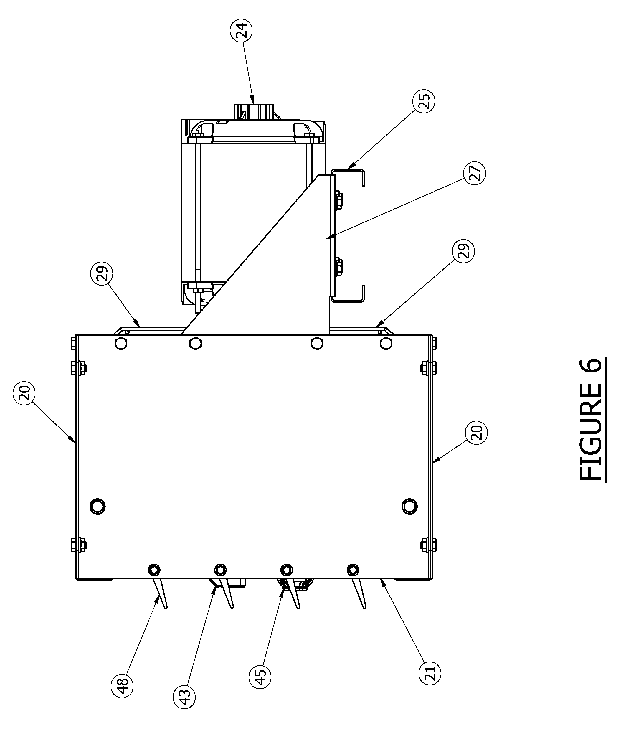
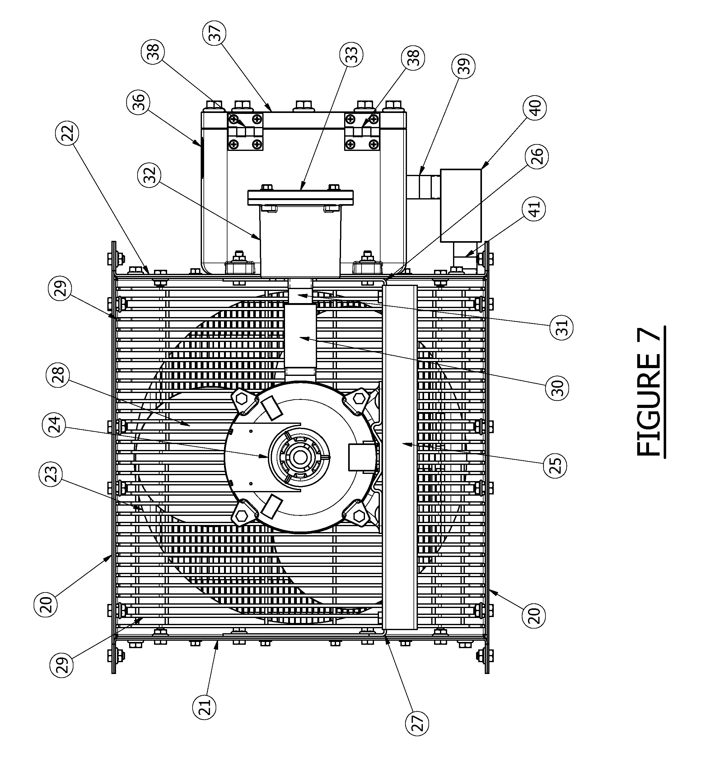
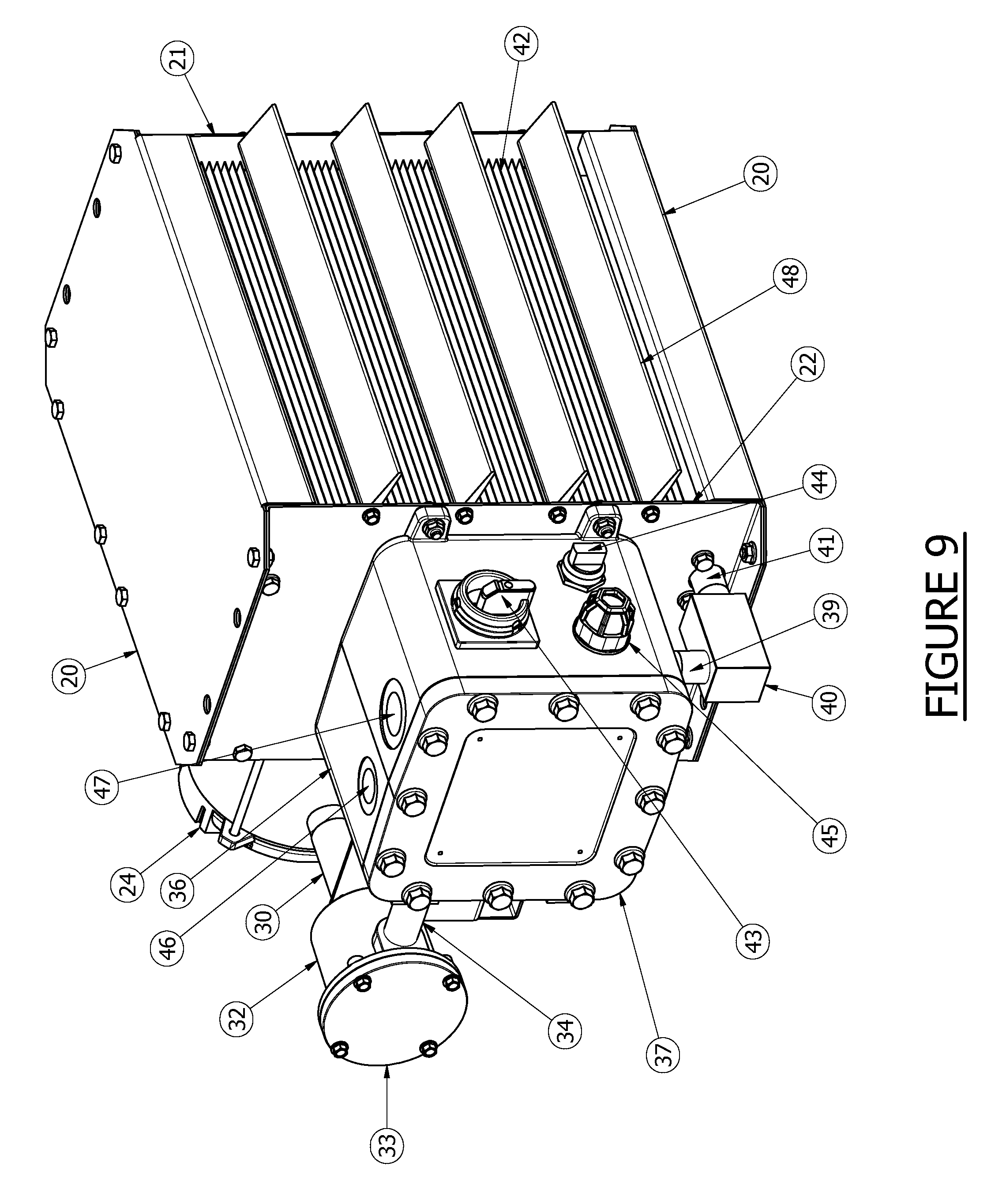
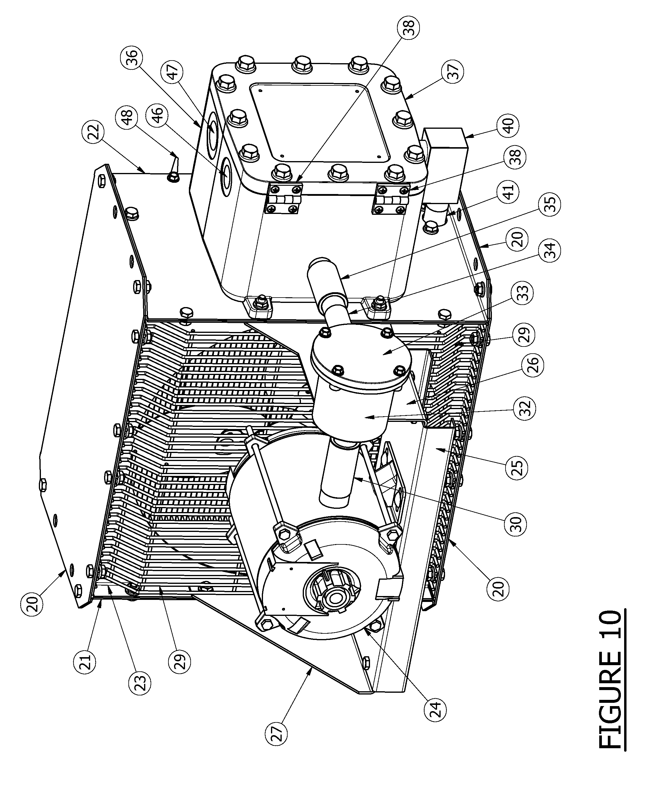
[0045] With reference to the drawings and in particular, FIGS. 4-10, the preferred embodiment of the present invention is comprised of a top and bottom cabinet 20 which is bolted to the right 21 and left 22 side cabinets, as well as the shroud cabinet 23. These cabinets 20, 21, 22, 23 are all preferably formed of sheet metal. An explosion proof electric motor 24 is then bolted to the motor mount 25, which is bolted to the motor enclosure mount bracket 26 and the motor mount bracket 27. Similarly, the mount brackets 25, 26, 27 are preferably formed of sheet metal and are all bolted to the cabinet. An axial air mover 28 made of non-sparking materials is secured to the shaft of the electric motor 24. The axial air mover 28 is centered on the shroud cabinet 23 and an axial mover guard 29, preferably constructed of metal wire, is bolted to the shroud cabinet 23. An expandable motor fitting 30, preferably manufactured from non-sparking metal, is threaded onto the motor casing. The expandable motor enclosure fitting 31, preferably manufactured from non-sparking metal, slides inside the expandable motor fitting 30 and is threaded into the motor enclosure box 32 which is preferably constructed of a non-sparking cast metal. The motor enclosure box 32 is bolted to the motor enclosure mount bracket 26 and has a motor enclosure cover 33, preferably constructed of a non-sparking cast metal, bolted on. This motor enclosure box 32 may hold a built in thermostatic switch 17 as per FIGS. 1 and 2, as opposed to a preferred cover 33.
[0046] An expandable fitting 34, preferably manufactured from a non-sparking metal, is threaded into the motor enclosure box 32 and the opposing side slides inside an expandable centralized enclosure fitting 35, preferably manufactured from a non-sparking metal. The expandable centralized enclosure fitting 35 is then threaded into the centralized enclosure box 36 which is preferably constructed of a non-sparking cast metal.
[0047] The centralized enclosure box 36 houses, but is not limited to, the following components as per FIGS. 1 and 2: A possible disconnect switch 1, a possible electronic control circuit board 9 with a built in time monitoring device 18, a possible solid state relay 6, 7, a possible current monitoring device 5, 8, a possible audible device 12, a possible communication port 15, and a possible enclosure high ambient temperature monitoring device 16.
[0048] The centralized enclosure box 36 is closed off by a centralized enclosure cover 37 that is preferably bolted-on and hinges on a preferably bolted-on hinging device 38.
[0049] An expandable fitting 39, preferable manufactured from a non-sparking metal, slides inside the centralized enclosure box 36 and is preferably threaded in a bulkhead 40 that is preferably manufactured from a non-sparking metal. An expandable fitting 41, preferably manufactured from a non-sparking metal, slides inside the bulk head 40 and threads into the heat transfer media 42.
[0050] The use of expandable fittings simplifies the installation process and ensures the fittings can expand and retract when the ambient temperature fluctuates.
[0051] An integral disconnect handle 43, two way switch handle 44, and illuminating device 45 are preferably mounted on the outside of the main enclosure box 36.
[0052] Port 46 represents a possible auxiliary entrance opening, while port 47 represents a preferable main power entrance opening.
[0053] An air deflecting device 48 provides the ability to direct the exiting air into the atmosphere.
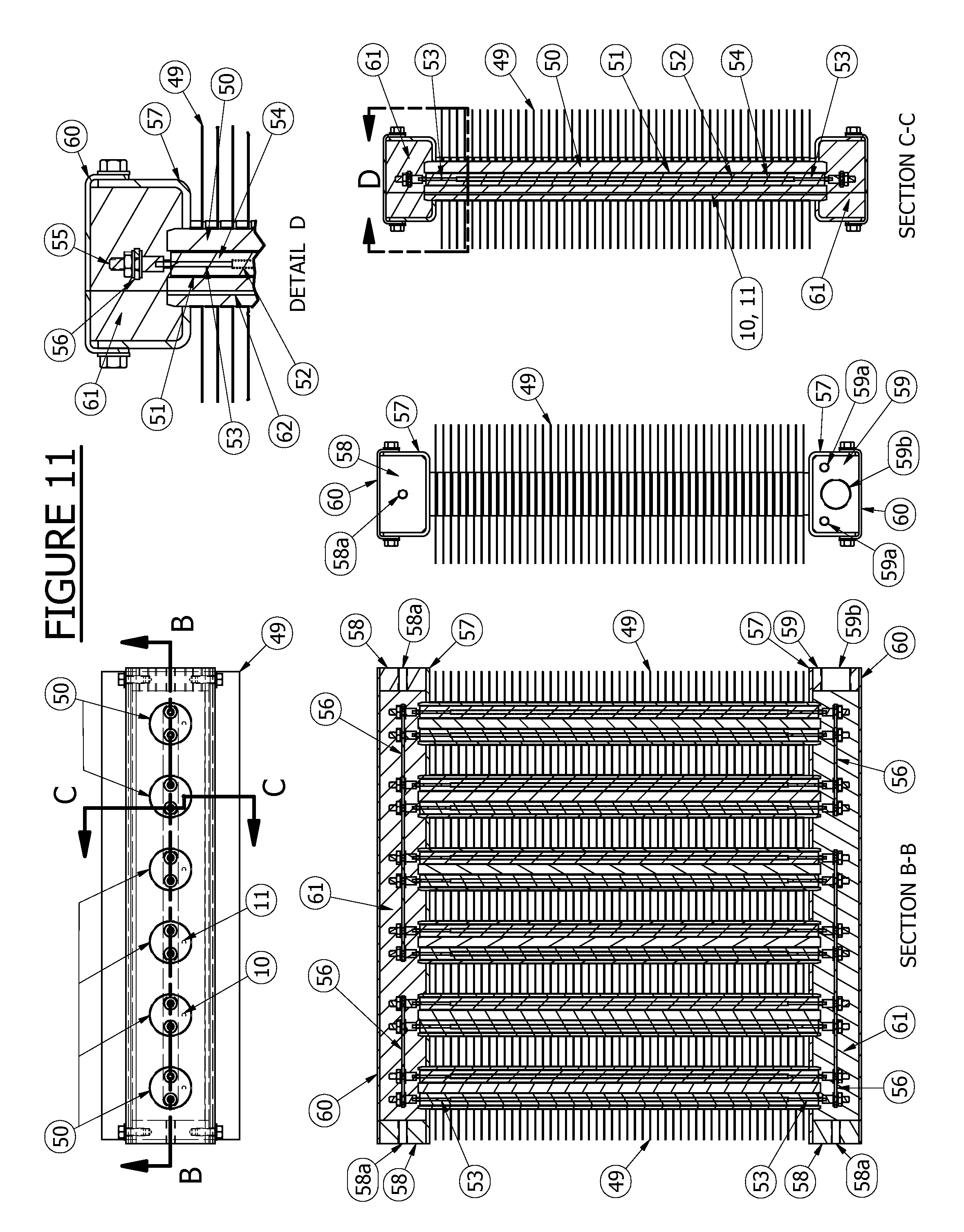
[0054] FIG. 11 illustrates a preferable breakdown of the heat transfer media 42 used in the current invention. A fin 49, preferably formed from a heat conductive metal, is preferably press fit onto preferably manufactured similar heat conductive metal tubes 50 that preferably have a heating element inserted within the body of the tube. The heating element is preferably made of conventional construction and includes: a tubular metal sheet 51, a resistor coil 52, and a cold pin 53. The cold pin 53 is housed within the metal sheath and compacted granular refractory material 54 within the sheath, to electrically insulate the coil from the sheath and conduct heat from the coil to the sheath. A fastening terminal 55, preferably manufactured from an electric conductive metal, is preferably crimped onto the cold pin 53 and provides a connection between an electrical transferring device 56, preferably manufactured from an electric conductive metal, and the other heating elements. A header 57, preferably formed of a heat conductive sheet metal, is press fit onto the metal tubes 50. The header 57 is enclosed by a header end 58 with a preferable threaded fastener provision 58a, a header end 59 with a preferable fastener provision 59a, and a threaded electric power entrance provision 59b. These components are covered and bolted with the header covers 60, which are preferably manufactured of a heat conductive metal. The header assembly forms an internal void, which is preferably filled with an electric resistant and heat conductive compound 61. The compound is poured within the header assembly once the metal components have been assembled and hardens as the compound cures. Once cured, the compound 61 forms a hard and resilient substance that replaces the need for a bulky flame proof enclosure. (For bulky flame proof enclosure example see prior art U.S. Pat. No. 4,117,308, items 72, 73, 82 and 83) An operating temperature monitoring device 10 and temperature high limit monitoring device 11 are preferably inserted into one of the metal tubes 50 within a pre-manufactured cavity 62.
[0055] FIG. 12 illustrates prior art. For reference see U.S. Pat. D 356,367. The prior art submerges electric heating elements 64 in a water glycol mixture within the bottom header 63. The metal tubes with spiral wound aluminum fins 65 form the heat transfer media and are connected to the bottom 64 and top header 66. The pressure safety device 67 provides an overpressure safety feature.
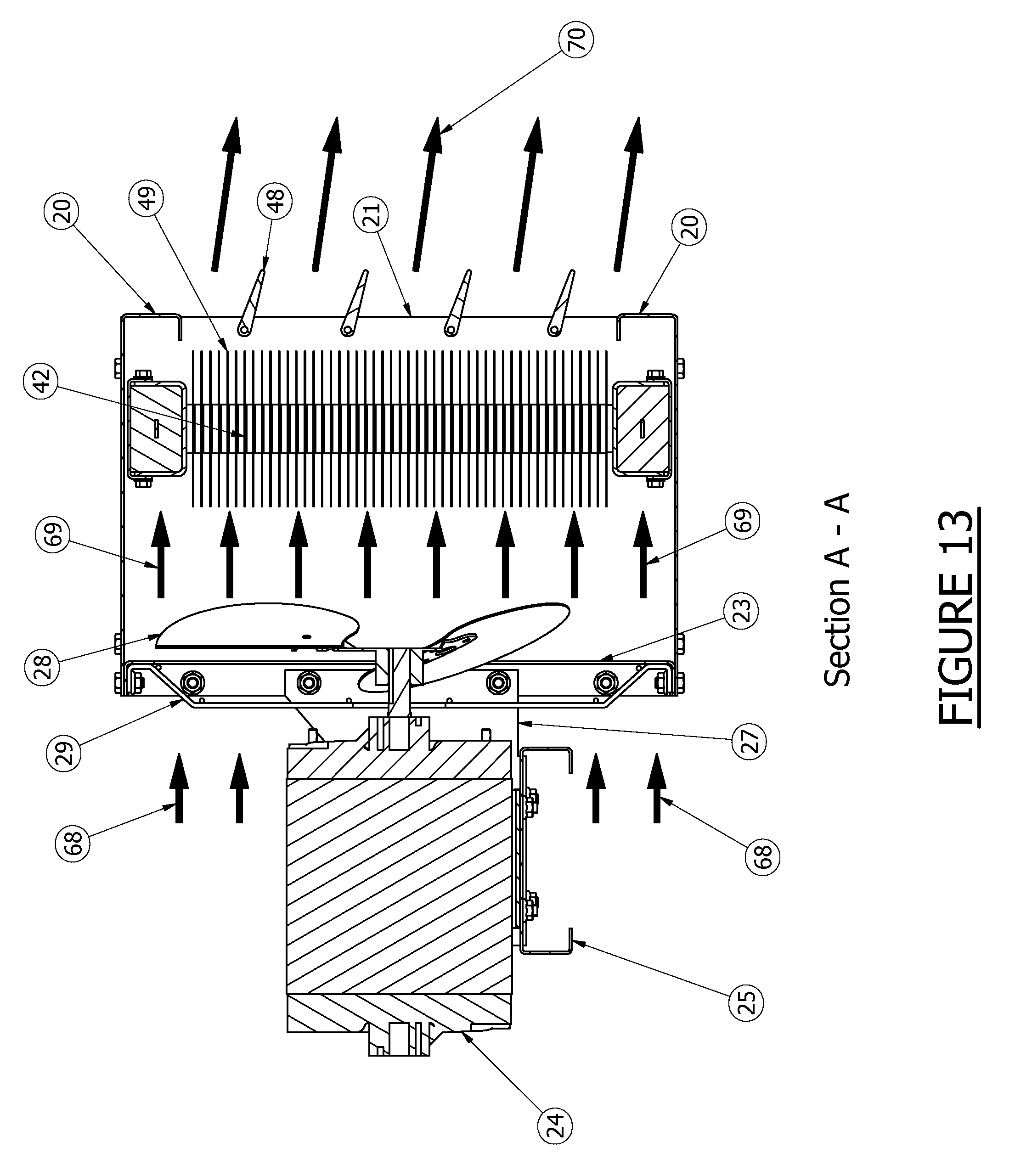
[0056] FIG. 13 illustrates the air flow characteristics of the present invention. Cool air 68 is drawn into the heater cabinet via an axial air mover 28. This accelerated cool air 69 is forced through the pre-heated heat transfer media 42. The heated fin 49 path causes the cool air 69 to warm up. As the air warms it expands, creating a higher exit velocity 70. This acceleration event is caused by particular and specific fin spacing. If the fins spacing is too wide there is insufficient heating surface, which leads to less than sufficient air flow resistance to generate the forced air to heat up, thus failing to provide a sufficient exit temperature increase. If the fin spacing is too narrow the air flow is restricted, causing excessive air flow resistance. This resistance causes the cool forced air 69 to bulk up behind the heat transfer media 42, thus causing hot air to exit the heat transfer media 42 with substantially slower air velocity, thereby defeating the purpose of a forced air heater.
[0057] FIG. 14 illustrates an added feature of the heat transfer media used in the present invention. The axial air mover 28 creates an area of decreased air movement in the centre of the heat transfer media 42. Because the center of the axial air mover is incapable of producing air movement, a hot spot could occur within the heat transfer media 42, as represented by the square perimeter 71. To eliminate the potential for a hot spot and premature resistor coil 52 burnout, the coil 52 embedded in the electrical heating element within the square perimeter 71 is substituted with a coil design that elicits a cooler heating area within the electrical heating element. The cooler heating area eliminates the hot spot scenario, while simultaneously conserving energy by ensuring areas incapable of heat dispersion remain cool during the heating cycle.
[0058] Although the invention has been described in connection with a preferred embodiment it should be understood that various modifications, additions and alterations may be made to the invention by one skilled in the art without departing from the spirit and scope of the invention as defined in the appended claims.
* * * * *
D00000
D00001
D00002
D00003
D00004
D00005
D00006
D00007
D00008
D00009
D00010
D00011
D00012

D00013
D00014

XML
uspto.report is an independent third-party trademark research tool that is not affiliated, endorsed, or sponsored by the United States Patent and Trademark Office (USPTO) or any other governmental organization. The information provided by uspto.report is based on publicly available data at the time of writing and is intended for informational purposes only.
While we strive to provide accurate and up-to-date information, we do not guarantee the accuracy, completeness, reliability, or suitability of the information displayed on this site. The use of this site is at your own risk. Any reliance you place on such information is therefore strictly at your own risk.
All official trademark data, including owner information, should be verified by visiting the official USPTO website at www.uspto.gov. This site is not intended to replace professional legal advice and should not be used as a substitute for consulting with a legal professional who is knowledgeable about trademark law.