Reflector Signal Lamp Having A Hidden Light Source
Kropac; Miroslav ; et al.
U.S. patent application number 13/527710 was filed with the patent office on 2012-12-27 for reflector signal lamp having a hidden light source. This patent application is currently assigned to VISTEON GLOBAL TECHNOLOGIES, INC.. Invention is credited to Martin Dluhos, Jan Kratochvil, Miroslav Kropac, Ludek Mazal, Pavel Tuma.
| Application Number | 20120327680 13/527710 |
| Document ID | / |
| Family ID | 47321488 |
| Filed Date | 2012-12-27 |


| United States Patent Application | 20120327680 |
| Kind Code | A1 |
| Kropac; Miroslav ; et al. | December 27, 2012 |
REFLECTOR SIGNAL LAMP HAVING A HIDDEN LIGHT SOURCE
Abstract
A signal lamp for a front and rear lighting of a vehicle includes at least one light source for emitting light, wherein the at least one light source is hidden from view; a reflector for reflecting the light emitted by the at least one light source away from the vehicle; and at least one light guide disposed between the reflector and a cover of the signal lamp, the at least one light guide having a first end and a second end, wherein the first end is disposed adjacent the at least one light source and the second end is located adjacent a focus point of the reflector.
| Inventors: | Kropac; Miroslav; (Ostrava, CZ) ; Kratochvil; Jan; (Novy Jicin, CZ) ; Mazal; Ludek; (Bilovec, CZ) ; Dluhos; Martin; (Novy Jicin, CZ) ; Tuma; Pavel; (Novy Jicin, CZ) |
| Assignee: | VISTEON GLOBAL TECHNOLOGIES,
INC. Van Buren Twp. MI |
| Family ID: | 47321488 |
| Appl. No.: | 13/527710 |
| Filed: | June 20, 2012 |
| Current U.S. Class: | 362/552 ; 362/511 |
| Current CPC Class: | F21S 43/243 20180101; F21S 43/40 20180101; F21S 43/249 20180101; F21S 43/14 20180101; F21S 43/237 20180101; F21S 43/245 20180101 |
| Class at Publication: | 362/552 ; 362/511 |
| International Class: | F21V 13/02 20060101 F21V013/02; F21V 13/12 20060101 F21V013/12; B60Q 1/00 20060101 B60Q001/00 |
Foreign Application Data
| Date | Code | Application Number |
|---|---|---|
| Jun 23, 2011 | CZ | PV 2011-372 |
Claims
1. A signal lamp for a vehicle, comprising: at least one hidden light source for emitting light; a reflector for reflecting the light emitted by the at least one light source away from the vehicle; and at least one light guide disposed between the reflector and a cover of the signal lamp to direct the light emitted by the at least one light source onto the reflector.
2. The signal lamp according to claim 1, wherein the at least one light source is hidden from view by a frame of the signal lamp.
3. The signal lamp according to claim 2, wherein the frame of the signal lamp is formed from a nontransparent material.
4. The signal lamp according to claim 2, wherein the frame is shaped to correspond to a shape of an outer peripheral edge of the reflector.
5. The signal lamp according to claim 1, wherein the at least one light source is disposed adjacent an outer peripheral edge of the reflector.
6. The signal lamp according to claim 1, wherein the at least one light source is an incandescent bulb.
7. The signal lamp according to claim 1, wherein the at least one light source is a light emitting diode.
8. The signal lamp according to claim 7, wherein the light emitting diode is disposed on a printed circuit board.
9. The signal lamp according to claim 1, wherein a first end of the at least one light guide is configured as a collimation component.
10. The signal lamp according to claim 1, wherein a second end of the at least one light guide is configured as a light scattering component.
11. The signal lamp according to claim 1, wherein a number of the at least one light source corresponds to a number of the at least one light guide.
12. The signal lamp according to claim 1, wherein at least a portion of a surface of the reflector includes at least one of a partially reflective coating and a fully reflective coating disposed thereon.
13. The signal lamp according to claim 1, wherein the reflector includes at least one parabolic surface.
14. The signal lamp according to claim 1, wherein the reflector includes at least one light scattering element formed thereon.
15. A signal lamp, comprising: at least one hidden light source for emitting light; a reflector for reflecting the light emitted by the at least one light source; and at least one light guide disposed between the reflector and a cover of the signal lamp to direct the light emitted by the at least one light source onto the reflector, the at least one light guide having a first end and a second end, wherein the first end is disposed adjacent the at least one light source and the second end is located adjacent a focus point of the reflector.
16. The signal lamp according to claim 15, wherein the first end of the at least one light guide is configured as a collimation component.
17. The signal lamp according to claim 15, wherein the second end of the at least one light guide is configured as a light scattering component.
18. A signal lamp, comprising: at least one light source for emitting light, wherein the at least one light source is hidden from view by a frame of the signal lamp; a reflector for reflecting the light emitted by the at least one light source, wherein the reflector includes at least one parabolic surface; and at least one light guide disposed between the reflector and a cover of the signal lamp to direct the light emitted by the at least one light source onto the reflector.
19. The signal lamp according to claim 18, wherein the reflector includes at least one light scattering element formed thereon.
20. The signal lamp according to claim 18, wherein at least a portion of a surface of the reflector includes at least one of a partially reflective coating and a fully reflective coating disposed thereon.
Description
CROSS-REFERENCE TO RELATED APPLICATION
[0001] This application claims the benefit of Czech Republic Patent Application No. PV 2011-372 filed Jun. 23, 2011, the entire disclosure of which is hereby incorporated herein by reference.
FIELD OF THE INVENTION
[0002] This invention pertains to a reflector signal lamp with a hidden light source, and more particularly to a reflector signal lamp with a hidden light source for a front and rear signal lighting of motor vehicles.
BACKGROUND OF THE INVENTION
[0003] Presently, signal lamps are used for front and rear running lights, brake lights, turn indicator lights, backup lights or fog lights in external automobile lighting. An optical system of the signal lamp, typically, includes a light source, a reflector, one or more optical filters, and an exterior lens.
[0004] The light sources used are bright incandescent light bulbs or light emitting diodes (LEDs).
[0005] Typically, there are two types of optical systems: direct and indirect.
[0006] A direct optical system has a visible light source situated approximately in a middle of a reflector. A direction of reflected light is in a direction of an axis of the light source.
[0007] On the other hand, indirect optical system has a visible light source situated at a side of a reflector, while a direction of reflected light is approximately perpendicular to an axis of the light source.
[0008] A certain portion of light emitted by the light source cannot be effectively reflected and is lost as direct light, thereby decreasing an efficiency of the optical system. Further, the light source can be easily recognized as a relatively bright object against a darker background of a reflecting surface of the reflector.
[0009] It would be desirable to produce a signal lamp having a hidden light source, wherein the light source is not visible from any direction, while a light emitting surface of the reflector is sufficiently visible.
SUMMARY OF THE INVENTION
[0010] In concordance and agreement with the present invention, a signal lamp having a hidden light source, wherein the light source is not visible from any direction, while a light emitting surface of the reflector is sufficiently visible, has been surprisingly invented.
[0011] In one embodiment, a signal lamp for a vehicle, comprises: at least one hidden light source for emitting light; a reflector for reflecting the light emitted by the at least one light source away from the vehicle; and at least one light guide disposed between the reflector and a cover of the signal lamp to direct the light emitted by the at least one light source onto the reflector.
[0012] In another embodiment, a signal lamp, comprises: at least one hidden light source for emitting light; a reflector for reflecting the light emitted by the at least one light source; and at least one light guide disposed between the reflector and a cover of the signal lamp to direct the light emitted by the at least one light source onto the reflector, the at least one light guide having a first end and a second end, wherein the first end is disposed adjacent the at least one light source and the second end is located adjacent a focus point of the reflector.
[0013] In yet another embodiment, a signal lamp, comprises: at least one light source for emitting light, wherein the at least one light source is hidden from view by a frame of the signal lamp; a reflector for reflecting the light emitted by the at least one light source, wherein the reflector includes at least one parabolic surface; and at least one light guide disposed between the reflector and a cover of the signal lamp to direct the light emitted by the at least one light source onto the reflector.
[0014] The essence of the invention being that at least one light source is arranged at an outer peripheral edge of a reflector behind a frame, which peripheral shape corresponds to a shape of the outer peripheral edge of the reflector, and which is made of nontransparent material, while a light guide has an exit end located at a focus point of the reflector. Moreover, the exit end of the light guide is configured as a light scattering component. The light guide also has an entry end configured as a collimation component.
[0015] Furthermore, the at least one light source of the signal lamp is an incandescent bulb or LED, and the LED is located on a rigid board provided with printed circuits. A number of the light sources corresponds to a number of light guide branches. The reflector includes a partly or fully light-reflecting surface. The reflector also includes one or more parabolic surfaces, which can be provided with light scattering elements.
BRIEF DESCRIPTION OF THE DRAWINGS
[0016] The above, as well as other advantages of the present invention, will become readily apparent to those skilled in the art from the following detailed description of the preferred embodiment when considered in the light of the accompanying drawings in which:
[0017] FIG. 1 is a schematic cross-sectional view of a signal lamp according to embodiment of the inventions, wherein the signal lamp has one hidden light source;
[0018] FIG. 2 is a schematic cross-sectional view of a signal lamp according to another embodiment of the invention, wherein the signal lamp has two hidden light sources;
[0019] FIG. 3A is a front elevational view of the signal lamp illustrated in FIG. 1;
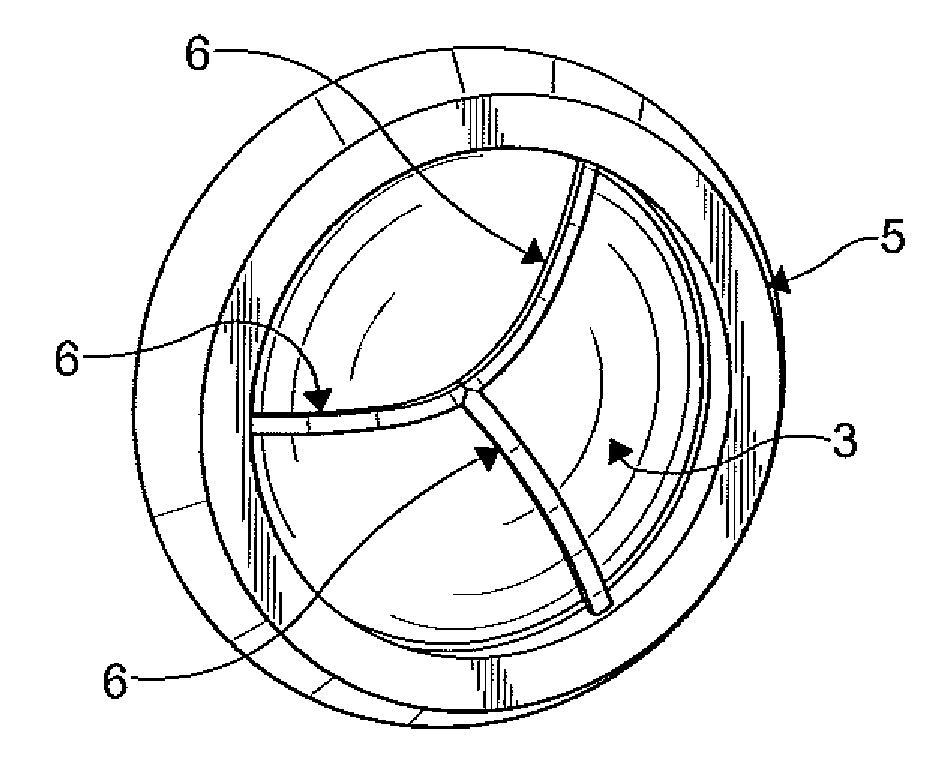
[0020] FIG. 3B is a front elevational view of a signal lamp according to another embodiment of the invention, wherein the signal lamp has three hidden light sources; and
[0021] FIG. 3C is a front elevational view of a signal lamp according to another embodiment of the invention, wherein the signal lamp has six hidden light sources.
DETAILED DESCRIPTION OF EXEMPLARY EMBODIMENTS OF THE INVENTION
[0022] The following detailed description and appended drawings describe and illustrate various embodiments of the invention. The description and drawings serve to enable one skilled in the art to make and use the invention, and are not intended to limit the scope of the invention in any manner.
[0023] FIG. 1 illustrates a signal lamp including an optical system according to an embodiment of the invention. The optical system includes a light source 1, a light guide 2, a frame 5, a reflector 3, and a cover 4. It is understood that the cover 4 can be formed from any suitable material such as a glass material, for example. Light emitted by the light source 1 is collimated and directed by the light guide 2 to the reflector 3, where the light is reflected on a first surface 31 and directed through the cover 4.
[0024] In certain embodiments, the light source 1 is a bright incandescent light bulb of the reflector 3 or light emitting diode (LED), which is placed around an edge of the signal lamp behind a frame 5, for example. As shown in FIG. 2, additional light sources 1 and light guides 2 can be employed if desired. For example, a single light source 1 is used in FIG. 3A, three light sources 1 are used in FIG. 3B, and six light sources are used in FIG. 3C. It is understood that the frame 5 can be made of any suitable material such as a nontransparent material.
[0025] An entry end 21 of the light guide 2 is configured as a collimation component 23. The collimation component 23 can be an optical collimator or a Fresnel lens which produces a collimated beam of light for a propagation of light in the light guide 2 without losses, for example.
[0026] An exit end 22 of the light guide 2, situated near a focus point F of the reflector 3, is configured as a light scattering component 24. The light scattering component 24 includes optical grooves, prisms, or other optical elements used to produce an evenly scattered light beam from the light guide 2 to the first surface 31 of the reflector 3 to increase a size of an light emitting surface.
[0027] The light guide 2 includes a plurality of branches 6. A number of the branches 6 is based upon a number of the light sources 1. It is understood that the light sources 1 can be LEDs placed on a rigid board with printed circuits in a single plane, as shown in FIG. 2.
[0028] As illustrated in FIG. 1, the first surface 31 of the reflector 3 is provided with a partly or fully reflective coating. The first surface 31 of the reflector 3 may be configured as a single parabolic surface or several parabolic surfaces having light scattering elements 32 formed therein. The light scattering elements 32 can improve a homogeneity of illumination of an illuminated surface of the reflector 3 and an overall visibility.
[0029] A size of the reflector 3 of the signal lamp depends on a type of signal function being provided. The signal lamps shown in FIGS. 1-3C produce sufficient light and a light scattering for a reflector 3 with the associated light guide 2.
[0030] When the LEDs are used as the light source 1, or light sources 1, in combination with a properly arranged light guide 2, and a main portion of the light emitted by the light source 1, or light sources 1, is properly utilized. Therefore, light losses for the light source 1, or light sources 1, are minimized. The signal lamp according to the invention is more efficient than signal lamps of the prior art.
[0031] Further, the reflector signal lamp with the hidden light source 1 in an on and off state is distinguishable from the signal lamps of the prior art.
[0032] The signal lamp having a hidden light source 1 has been developed to meet requirements of light division, light color and optimal composition of the light emitting surfaces, while maintaining safe signal registration.
* * * * *
D00000
D00001
D00002
D00003
XML
uspto.report is an independent third-party trademark research tool that is not affiliated, endorsed, or sponsored by the United States Patent and Trademark Office (USPTO) or any other governmental organization. The information provided by uspto.report is based on publicly available data at the time of writing and is intended for informational purposes only.
While we strive to provide accurate and up-to-date information, we do not guarantee the accuracy, completeness, reliability, or suitability of the information displayed on this site. The use of this site is at your own risk. Any reliance you place on such information is therefore strictly at your own risk.
All official trademark data, including owner information, should be verified by visiting the official USPTO website at www.uspto.gov. This site is not intended to replace professional legal advice and should not be used as a substitute for consulting with a legal professional who is knowledgeable about trademark law.