Lens Cover Mechanism For Projector
Yamaguchi; Toshiyuki ; et al.
U.S. patent application number 13/580636 was filed with the patent office on 2012-12-27 for lens cover mechanism for projector. Invention is credited to Yasushi Itou, Akio Morita, Toshiyuki Yamaguchi.
| Application Number | 20120327513 13/580636 |
| Document ID | / |
| Family ID | 44506289 |
| Filed Date | 2012-12-27 |


View All Diagrams
| United States Patent Application | 20120327513 |
| Kind Code | A1 |
| Yamaguchi; Toshiyuki ; et al. | December 27, 2012 |
LENS COVER MECHANISM FOR PROJECTOR
Abstract
The present invention provides a sliding lens cover mechanism for a projector, which enables enhancement in operability and prevention of noise, and the sliding lens cover mechanism includes: a front panel that allows the projection lens to be exposed from a part thereof; a lens cover that moves over said front panel, from fully-open state in which the projection lens is exposed and a fully-closed state in which said lens cover covers the projection lens; and a slide device unit that biases the lens cover to move to a fully-open state or to a fully-closed state or to an intermediate state, wherein the lens cover includes a pin that protrudes toward the front panel; and wherein the front panel includes a slide plate that abuts against the pin only in the fully open state or in the fully closed state.
| Inventors: | Yamaguchi; Toshiyuki; (Tokyo, JP) ; Morita; Akio; (Tokyo, JP) ; Itou; Yasushi; (Tokyo, JP) |
| Family ID: | 44506289 |
| Appl. No.: | 13/580636 |
| Filed: | February 25, 2010 |
| PCT Filed: | February 25, 2010 |
| PCT NO: | PCT/JP2010/052960 |
| 371 Date: | August 22, 2012 |
| Current U.S. Class: | 359/511 |
| Current CPC Class: | G03B 21/145 20130101 |
| Class at Publication: | 359/511 |
| International Class: | G03B 21/14 20060101 G03B021/14 |
Claims
1. A lens cover mechanism for covering a projection lens of a projector, the lens cover mechanism comprising: a front panel that allows the projection lens to be exposed from a part thereof; a lens cover that moves over said front panel, from fully-open state in which the projection lens is exposed and a fully-closed state in which said lens cover covers the projection lens; and a slide device unit that biases the lens cover to move to a fully-open state or to a fully-closed state, wherein said lens cover includes a pin that protrudes toward said front panel; and Wherein said front panel includes a slide plate that only abuts against said pin in a fully-open state or in a fully-closed state.
2. The lens cover mechanism according to claim 1, wherein said slide plate extends in a direction in which said lens cover slides; wherein when said lens cover is in the fully-open state or when said lens cover is in the fully-closed state, said pin is in contact with said slide plate; and wherein when said lens cover transitions from the fully-open state to the fully-closed state and when said lens cover transitions from the fully-closed state to the fully-open state, said pin is away from said slide plate.
3. The lens cover mechanism for a projector according to claim 2, wherein said lens cover includes a rib at an end thereof, the rib protruding toward said front panel; and wherein said front panel includes a protrusion that is in contact with the rib only in the fully-open state, and a guide portion that is in contact with the rib only in the fully-closed state.
Description
TECHNICAL FIELD
[0001] The present invention relates to a projector that projects image light via a projection lens, and specifically relates to a lens cover mechanism for protecting the projection lens.
BACKGROUND ART
[0002] For liquid-crystal projectors and projectors that generate image light using a DMD (digital micromirror device) and project the image light via a projection lens, lens covers that cover a projection lens are used in order to protect the projection lens when no projection is performed.
[0003] Examples of the lens covers include those having the shape of a cap, which are attached to the projection lens, and sliding-type ones in which a part of a chassis of the projector slides and covers the projection lens.
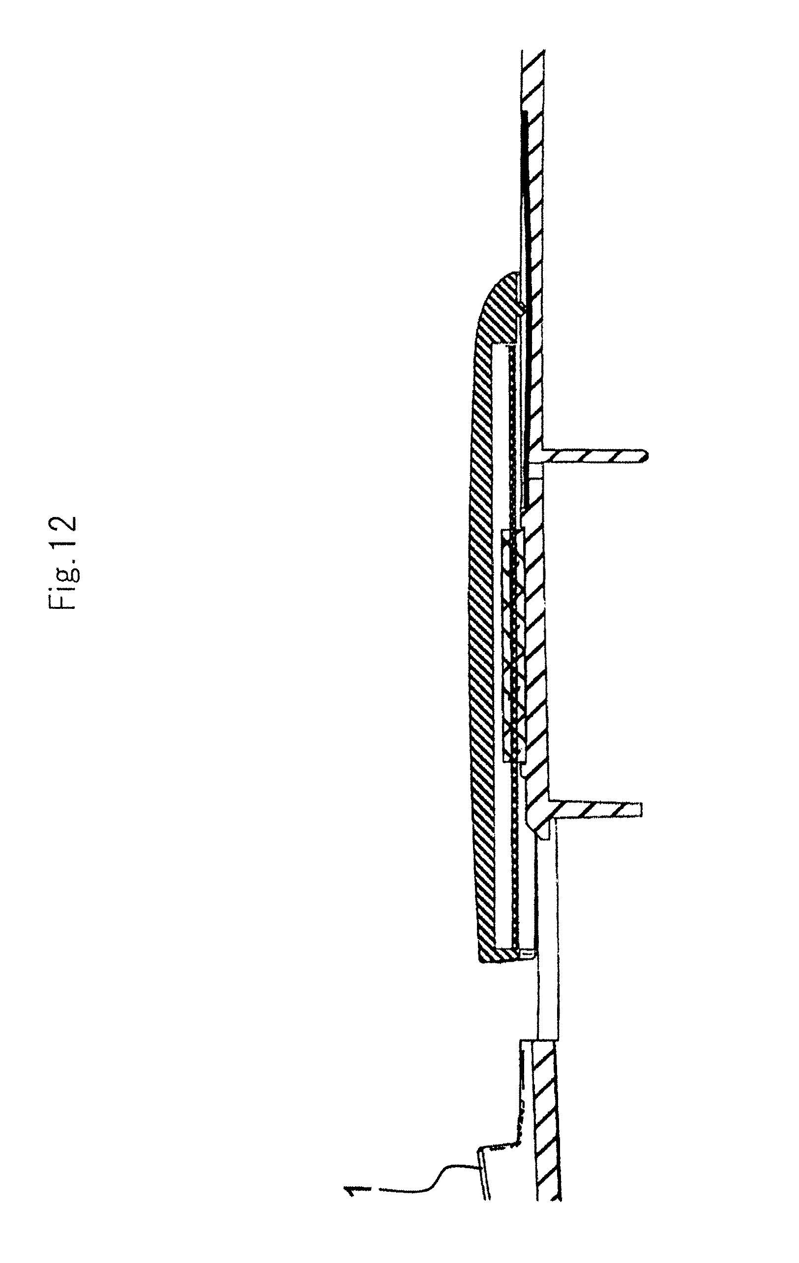
[0004] Although those that have the shape of a cap may be lost, the sliding covers will not be lost because they are integrated with the chasses of the projectors.
[0005] Examples of the sliding covers include one disclosed in Patent Literature 1 (JP2-44729U) and Patent Literature 2 (JP2008-102376A).
[0006] The one disclosed in Patent Literature 1 is a lens cover that is only manually slidable.
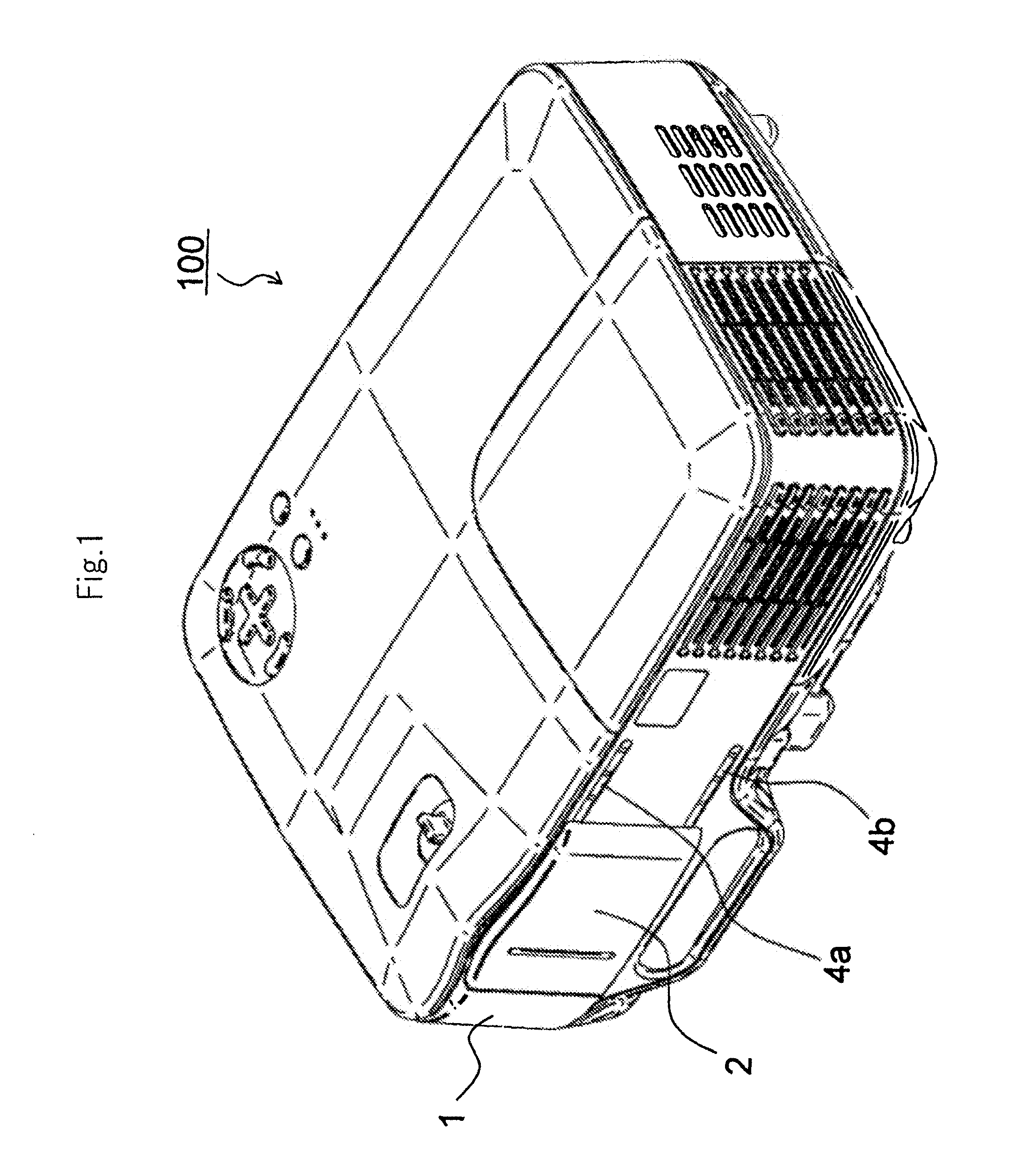
[0007] A lens cover that is only manually slidable, like the one in Patent Literature 1, may stop between a fully-open state and a fully-closed state, and thus, an operator needs to operate the lens cover in such a way that it is moved to the fully open state or to the fully closed state, because of lens cover may stop in the intermediate state, and such operation is troublesome.
[0008] The lens cover disclosed in Patent Literature 2 has been made in view of the problem arising in the above technique disclosed in Patent Literature 1, and is provided with a biasing means for biasing a lens cover to move to a full open state or to a fully closed date.
CITATION LIST
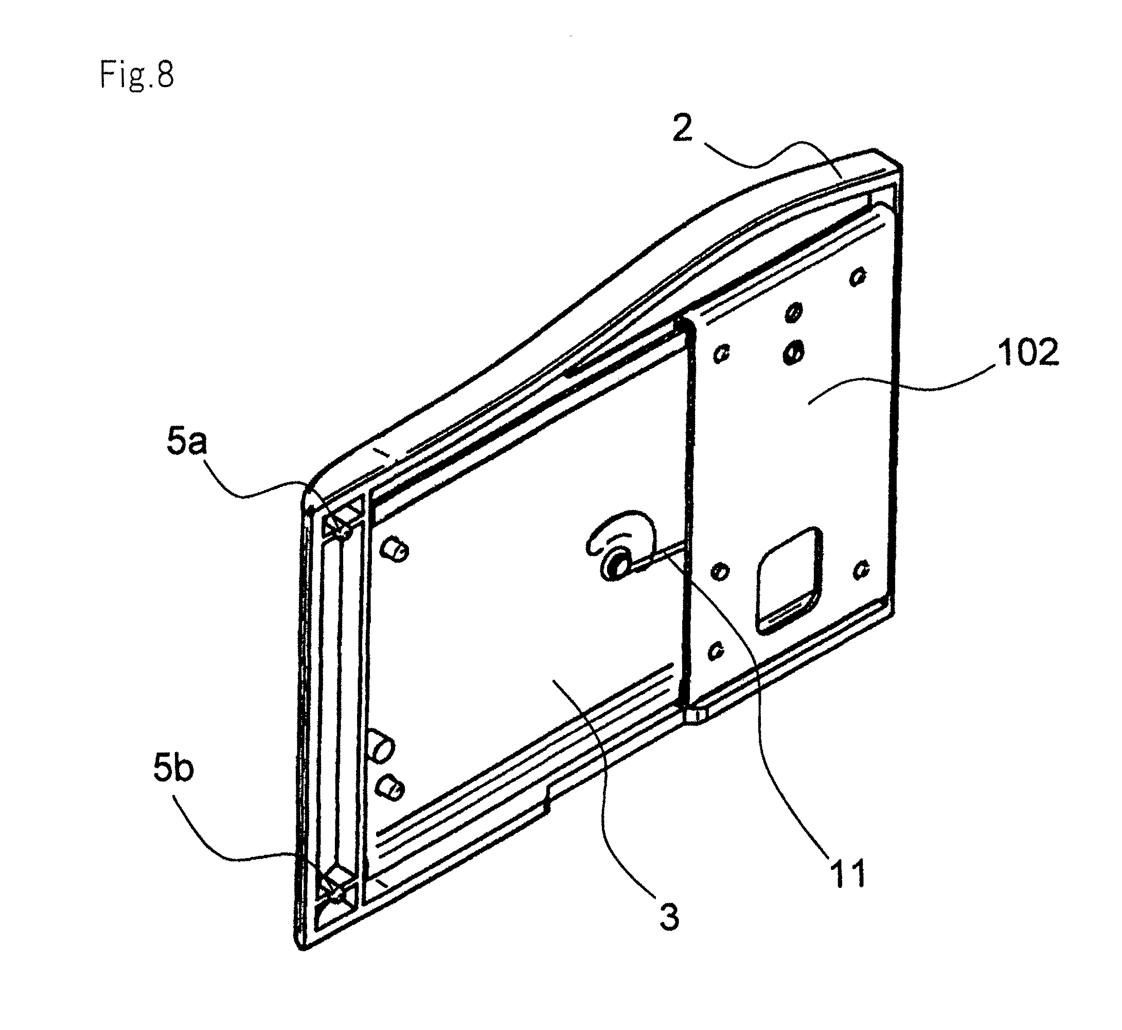
Patent Literature
[0009] Patent Literature 1: P2-44729U
[0010] Patent Literature 2: P2008-102376A
SUMMARY OF INVENTION
Technical Problem
[0011] A troublesome operation is required to operate the lens cover described in Patent Literature 1. The one described in Patent Literature 2 provides improvement in operability because of the provision of the biasing means.
[0012] More and more projectors use a brighter light source to increase brightness. A common cooling mechanism in the light source is a fan, which requires a large amount of airflow, and which causes a large amount of vibration.
[0013] In addition to business applications, such as briefings in meetings, projectors are used, for example, for video watching in general households. In any case, noise generation is not desirable. As described above, projectors include a vibration source, and each of the components included in a projector requires a structure that prevents noise from being generated according to vibration.
[0014] Operating the lens cover described in Patent Literature 1 is troublesome and improvement in the operability of the lens cover described in Patent Literature 2 is achieved by providing biasing means; however, no specific description is provided in terms of indicating a structure that can prevent the generation of noise.
[0015] The present invention is intended to provide a sliding lens cover mechanism for a projector, which enables enhancement in operability and prevention of noise generation.
Solution to Problem
[0016] A lens cover mechanism for a projector according to the present invention includes a lens cover mechanism for covering a projection lens of a projector,
[0017] a lens cover mechanism for covering the projection lens of a projector, the lens cover mechanism including:
[0018] a front panel that allows the projection lens to be exposed from a part thereof;
[0019] a lens cover that moves over the front panel between a fully-open state in which the projection lens is exposed and a fully-closed state in which the lens cover covers the projection lens; and
[0020] A slide device unit that biases the lens cover to move to a fully-open state or to a fully-closed state,
[0021] wherein the lens cover includes a pin that protrudes toward the front panel; and
[0022] wherein the front panel includes a slide plate that abuts against the pin only in the fully-open state or in the fully-closed state.
Advantageous Effects of Invention
[0023] In the present invention, a lens cover for a projector has a smooth sliding operation, and there is no negative reaction when the lens cover is in a fully open or a fully closed state, whereby noise generation is prevented.
BRIEF DESCRIPTION OF DRAWINGS
[0024] FIG. 1 is a perspective diagram illustrating a configuration of an exemplary embodiment of a projector including a lens cover mechanism according to the present invention.
[0025] FIG. 2 is a front view of a state in which lens cover 2 is closed in FIG. 1.
[0026] FIG. 3 is a perspective diagram illustrating a configuration of an exemplary embodiment of a projector including a lens cover mechanism according to the present invention.
[0027] FIG. 4 is a front view of a state in which lens cover 2 is open in FIG. 1.
[0028] FIG. 5 is a front view of a state in which a lens cover is in an intermediate state.
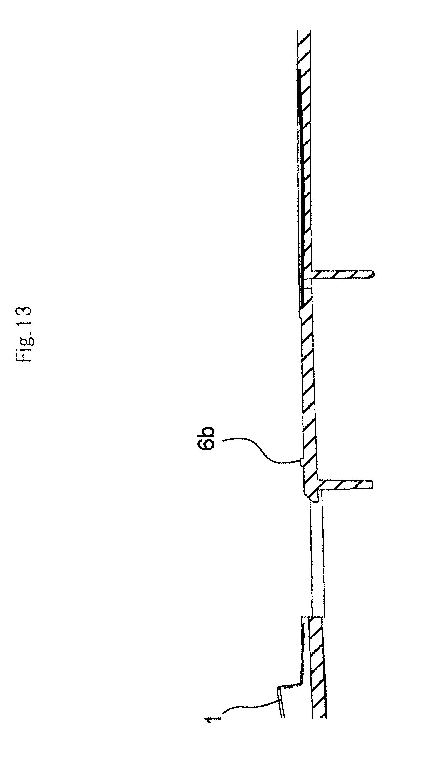
[0029] FIG. 6 is a front view of front panel 1 in FIG. 1.
[0030] FIG. 7 is an exploded perspective diagram illustrating the configuration of the exemplary embodiment illustrated in FIG. 1 in more detail.
[0031] FIG. 8 is a perspective view of lens cover 2 and slide mechanism unit 3, which have been assembled together, on the front panel 1 side.
[0032] FIG. 9 is a perspective view of lens cover 2 and slide mechanism unit 3, which have been assembled together, on the front panel 1 side.
[0033] FIG. 10 is a cross-sectional view along double arrow-headed line A-A in FIG. 2.
[0034] FIG. 11 is a cross-sectional view along double arrow-headed line B-B in FIG. 4.
[0035] FIG. 12 is a cross-sectional view along double arrow-headed line C-C in FIG. 5.
[0036] FIG. 13 is a cross-sectional view along double arrow-headed line D-D in FIG. 6.
DESCRIPTION OF EMBODIMENT
[0037] Next, an exemplary embodiment will be described with reference to the drawings.
[0038] FIGS. 1 and 3 are perspective diagrams each illustrating an exemplary embodiment of projector 100 including a lens cover mechanism according to the present invention. FIG. 3 illustrates a state in which lens cover 2 is open when, e.g., image light is projected from projection lens 101, and FIG. 1 illustrates a state in which projection lens 101 is covered by lens cover 2.
[0039] As illustrated in FIG. 3, projection lens 101 is exposed from a part of front panel 1 of projector 100, and lens cover 2 for covering projection lens 101 is attached to front panel 1. As illustrated in the front views in FIGS. 2 and 4, lens cover 2 moves in the horizontal direction in FIGS. 2 and 4.
[0040] FIG. 2 illustrates a state in which lens cover 2 has moved to the leftmost position in FIG. 2 whereby projection lens 101 is covered by lens cover 2, and FIG. 4 illustrates a state in which lens cover 2 has moved to the rightmost position in FIG. 4 whereby lens cover 2 is open when, e.g., image light is projected from projection lens 101.
[0041] FIG. 7 is an exploded perspective diagram illustrating the configuration of the present exemplary embodiment in more detail. FIGS. 8 and 9 are a perspective view and a plan view of lens cover 2 and slide mechanism unit 3 respectively, which have been assembled together, on the front panel 1 side.
[0042] Attachment panel 102 is secured to front panel 1 via screws (not illustrated). Meanwhile, slide mechanism unit 3 is movably assembled with attachment panel 102 via torsion spring 11. Lens cover 2 is integrated with slide mechanism unit 3 by means of a double-sided adhesive tape and thermal welding (not illustrated). In other words, lens cover 2 and slide mechanism unit 3 slide over front panel 1.
[0043] FIG. 9 illustrates a state in which lens cover 2 is open and image light is projected from projection lens 101, and which is the same as the state illustrated in FIG. 4. In the state illustrated in FIG. 9, slide mechanism unit 3 is biased by torsion spring 11 to the left in the Figure, whereby the fully-open state of lens cover 2 is maintained.
[0044] When lens cover 2 is closed, lens cover 2 is moved to the right in the Figure by means of a user's operation. In this movement of lens cover 2, first, torsion spring 11 exerts a spring force in the direction in which lens cover 2 has been closed because torsion spring 11 has become compressed, but when the intermediate point, where torsion spring 11 is compressed the most, has been reached, torsion spring 11 starts to unfurl, and as a result, torsion spring 11 exerts a spring force in the direction in which lens cover 2 is opened.
[0045] As illustrated in FIG. 8, pins 5a and 5b protruding toward front panel 1 are provided at one end of lens cover 2 (right end viewed from the front side when lens cover 2 is attached to front panel 1). In the fully-open state illustrated in, e.g., FIG. 1, pins 5a and 5b that are provided in lens cover 2 abut against slide plates 4a and 4b.
[0046] FIG. 10 is a cross-sectional view along double arrow-headed line A-A in FIG. 2. As illustrated in FIGS. 7 and 10, protrusions 6a and 6b protruding toward lens cover 2 are provided in front panel 1. As illustrated in FIG. 10, in a state in which lens cover 2 is fully closed, protrusions 6a and 6b of front panel 1 are not in contact with lens cover 2.
[0047] FIG. 11 is a cross-sectional view along double arrow-headed line B-B in FIG. 4. As illustrated in FIG. 11, at another end of lens cover 2 (left end viewed from the front side when lens cover 2 is attached to front panel 1), rib 8 is formed as a result of the other end being flexed toward front panel 1. Guide portions 7a and 7b (see FIG. 7) each having a shape that fits rib 8 are provided in front panel 1. When lens cover 2 is in a fully-closed state, rib 8 of lens cover 2 abuts against guide portions 7a and 7b of front panel 1.
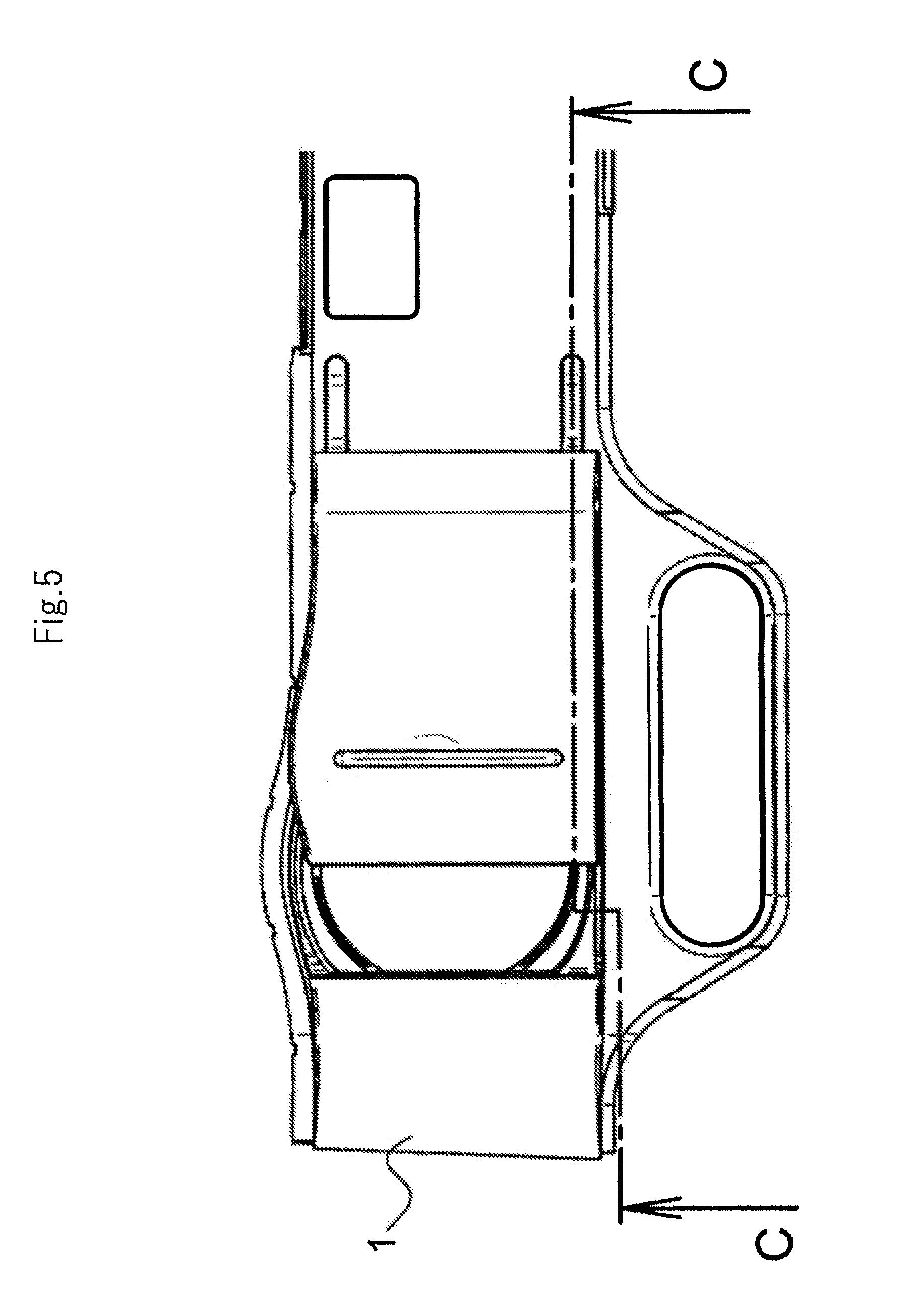
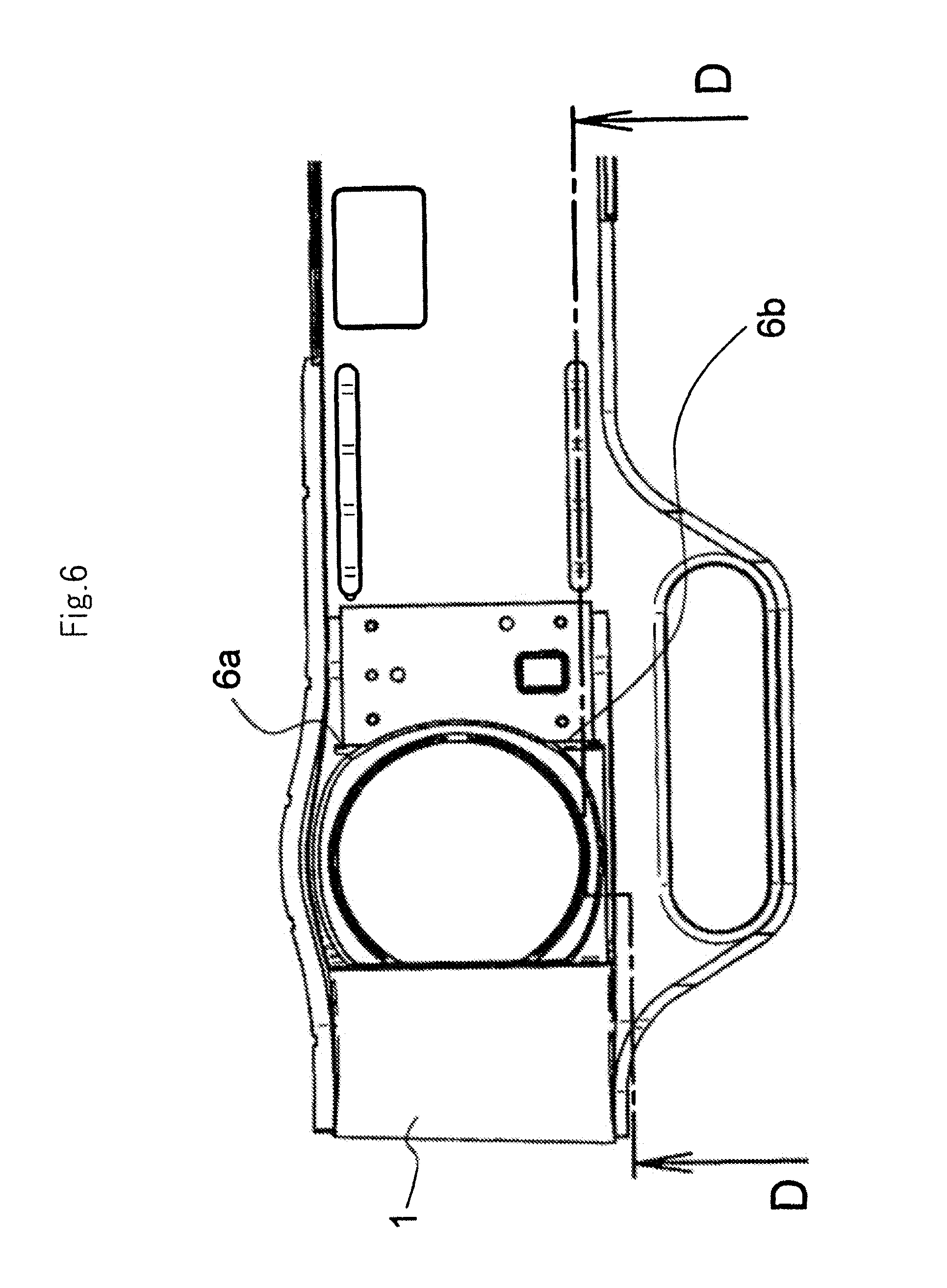
[0048] FIG. 5 is a front view of lens cover 2 at a certain point of time during an opening/closing operation, FIG. 6 is a front view of front panel 1, FIG. 12 is a cross-sectional view along double headed-arrow line C-C in FIG. 5, and FIG. 13 is a cross-sectional view along double headed-arrow line D-D in FIG. 6.
[0049] An opening/closing operation of lens cover 2 according to the present exemplary embodiment, which is configured as described above, will be described in detail with reference to FIGS. 5, 6, 12 and 13 in addition to the aforementioned Figures.
[0050] As illustrated in FIGS. 5 and 12, when lens cover 2 is manually made to slide to the left away from a state in which lens cover 2 is fully open, lens cover 2, when it has reached a part way position, is slid to a fully closed state by torsion spring 11.
[0051] When lens cover 2 is made to move, as described above, if front panel 1 and lens cover 2 are in contact with each other, a friction force is generated, and if the friction force is larger than the spring force of torsion spring 11, lens cover 2 is not moved to a fully closed state.
[0052] In the present exemplary embodiment, front panel 1 and lens cover 2 are not in contact with each other in the intermediate state, and thus, lens cover 2 is moved to a fully-closed state.
[0053] In the present exemplary embodiment, front panel 1 and lens cover 2 are configured so as to be in contact with each other only in a fully-open state and a fully-closed state.
[0054] Pins 5a and 5b are provided at one end of lens cover 2, and rib 8 is provided at another end of lens cover 2. Furthermore, slide plates 4a and 4b, protrusions 6a and 6b and guide portions 7a and 7b are provided in front panel 1.
[0055] Slide plates 4a and 4b extend along a direction in which lens cover 2 slides, and abut against pins 5a and 5b only when lens cover 2 is in a fully-open state and only when lens cover 2 is in a fully-closed state. Guide portions 7a and 7b abut against rib 8 only when lens cover 2 is in a fully-closed state. Protrusions 6a and 6b abut against rib 8 only when lens cover 2 is in a fully-open state.
[0056] In order to cause slide plates 4a and 4b to be in contact with pins 5a and 5b of lens cover 2 only when lens cover 2 is in an fully-open state and only when lens cover 2 is in a fully-closed state, and to cause slide plates 4a and 4b not to be in contact with pins 5a and 5b in an intermediate state, slide plates 4a and 4b each have a recessed shape that protrudes closest to lens cover 2 at respective positions corresponding to pins 5a and 5b when lens cover 2 is in an fully-open state and away from the lens covers between these states.
[0057] Furthermore, guide portions 7a and 7b each have a shape, only a left end portion of which protrudes toward lens cover 2 so that guide portions 7a and 7b are in contact with rib 8 of lens cover 2 in a fully-closed state and are not in contact with rib 8 before lens cover 2 enters the fully-closed state.
[0058] In the present exemplary embodiment configured as described above, in the state illustrated in FIGS. 3, 4 and 11 in which lens cover 2 is fully open, pins 5a and 5b that are provided at the back surface of lens cover 2 abut against slide plates 4a and 4b, and rib 8 of lens cover 2 abuts against protrusions 6a and 6b of the front panel.
[0059] In the state illustrated in FIGS. 1, 2 and 10 in which lens cover 2 is fully closed, pins 5a and 5b provided at the back surface of lens cover 2 abut against slide plates 4a and 4b, and rib 8 of lens cover 2 abuts against guide portions 7a and 7b of the front panel.
[0060] In the present exemplary embodiment, front panel 1 and lens cover 2 are in contact with each other at four positions in each fully-open state and each fully-closed state of lens cover 2. Accordingly, there is no negative reaction, and thus, no noise is generated. Furthermore, no depth difference occurs between front panel 1 and lens cover 2.
[0061] Furthermore, slide plates 4a and 4b each have a recessed shape that protrudes closest to lens cover 2 at two positions, i.e., a position corresponding to respective pin 5a or 5b when lens cover 2 is in a fully-open state, and a position corresponding to respective pin 5a or 5b when lens cover 2 is in a fully-closed state and when plates 4a and 4b are not close to lens cover 2 when lenscover 2 is in an intermediate state. Thus, in an intermediate state such as illustrated in FIGS. 5 and FIG. 12, slide plate 4a and pin 5a, slide plate 4b and pin 5b, protrusion 6a and rib 8, protrusion 6b and rib 8, guide portion 7a and rib 8, and guide portion 7b and rib 8 are not in contact with each other, and lens cover 2 slides smoothly.
REFERENCE SIGNS LIST
[0062] 1 front panel [0063] 2 lens cover [0064] 3 slide mechanism unit [0065] 4a slide plate [0066] 4b slide plate [0067] 5a pin [0068] 5b pin [0069] 6a protrusion [0070] 6b protrusion [0071] 7a guide portion [0072] 7b guide portion [0073] 8 rib [0074] 11 torsion spring [0075] 100 projector [0076] 101 projection lens
* * * * *
D00000
D00001
D00002
D00003
D00004
D00005
D00006
D00007
D00008
D00009
D00010
D00011
D00012
D00013
XML
uspto.report is an independent third-party trademark research tool that is not affiliated, endorsed, or sponsored by the United States Patent and Trademark Office (USPTO) or any other governmental organization. The information provided by uspto.report is based on publicly available data at the time of writing and is intended for informational purposes only.
While we strive to provide accurate and up-to-date information, we do not guarantee the accuracy, completeness, reliability, or suitability of the information displayed on this site. The use of this site is at your own risk. Any reliance you place on such information is therefore strictly at your own risk.
All official trademark data, including owner information, should be verified by visiting the official USPTO website at www.uspto.gov. This site is not intended to replace professional legal advice and should not be used as a substitute for consulting with a legal professional who is knowledgeable about trademark law.