Capacitive Sensor And Detection Method Using The Same
LEE; CHENG-HAN ; et al.
U.S. patent application number 13/606261 was filed with the patent office on 2012-12-27 for capacitive sensor and detection method using the same. This patent application is currently assigned to EGALAX_EMPIA TECHNOLOGY INC.. Invention is credited to CHENG-HAN LEE, CHI-HAO TANG.
| Application Number | 20120327026 13/606261 |
| Document ID | / |
| Family ID | 46454889 |
| Filed Date | 2012-12-27 |


| United States Patent Application | 20120327026 |
| Kind Code | A1 |
| LEE; CHENG-HAN ; et al. | December 27, 2012 |
CAPACITIVE SENSOR AND DETECTION METHOD USING THE SAME
Abstract
The present invention provides a capacitive sensor and a detection method using the same. The capacitive sensor of the present invention includes a plurality of detecting plates arranged sequentially. Each detecting plate is provided with the same driving signal. According to the difference between signals of each detecting plate and another detecting plate, detecting plates touched or approached by external objects can be identified.
| Inventors: | LEE; CHENG-HAN; (Taipei City, TW) ; TANG; CHI-HAO; (Taipei City, TW) |
| Assignee: | EGALAX_EMPIA TECHNOLOGY
INC. Taipei City TW |
| Family ID: | 46454889 |
| Appl. No.: | 13/606261 |
| Filed: | September 7, 2012 |
| Current U.S. Class: | 345/174 |
| Current CPC Class: | G06F 3/04164 20190501; G06F 3/04166 20190501; G06F 3/0446 20190501; H03K 17/9622 20130101; G06F 2203/04106 20130101; G06F 3/047 20130101; G06F 3/041 20130101; G06F 2203/04112 20130101; H03K 2017/9602 20130101; H03K 17/962 20130101; G06F 2203/04104 20130101; G06F 3/04186 20190501 |
| Class at Publication: | 345/174 |
| International Class: | G06F 3/044 20060101 G06F003/044 |
Foreign Application Data
| Date | Code | Application Number |
|---|---|---|
| Jan 7, 2011 | TW | 100100564 |
Claims
1. A capacitive sensor comprising: a plurality of sequentially arranged detecting plates; at least one reference plate disposed between the detecting plates; a memory for storing a lookup table, wherein the lookup table defines corresponding relationships between a plurality of signal differences or amounts of change in signal difference and the detecting plate being touched/approached; and a controller that simultaneously provides an electrical signal to each detecting plate, and provides the electrical signal or a DC potential to the reference plate, so that the signal difference or the amount of change in signal difference is generated by subtraction between signals of each detecting plate and another detecting plate, and determines if at least one detecting plate is touched or approached by at least one external object by using the lookup table based on the signal differences.
2. The capacitive sensor of claim 1, wherein the controller designates one of the detecting plates as a specific detecting plate, and each signal difference or the amount of change in signal difference is generated by subtraction between signals from one of non-specific detecting plates and the specific detecting plate.
3. The capacitive sensor of claim 1, wherein each signal difference or the amount of change in signal difference is generated by subtraction between signals from one of the detecting plates and a preceding detecting plate.
4. A capacitive sensor comprising: a plurality of sequentially arranged detecting plates; at least one reference plate disposed between the detecting plates; and a controller that simultaneously provides an electrical signal to each detecting plate, and provides the electrical signal or a DC potential to the at least one reference plate, or simultaneously provides an electrical signal to each reference plate, so that a signal difference is generated by subtraction between signals from each of the detecting plate and a preceding detecting plate, and the signal differences are combined to form a plurality of continuous signal differences, and each signal difference of the continuous signal differences is added to all the preceding or following signal differences to generate a plurality of continuous recovered signal values, and it is determined whether at least one detecting plate is touched or approached by at least one external object based on the continuous recovered signal values.
5. The capacitive sensor of claim 4, wherein the continuous recovered signal values further include an additionally added zero and each of the continuous recovered signal values correspond to one of the detecting plates, respectively.
6. The capacitive sensor of claim 5, wherein a detecting plate corresponding to a recovered signal value that exceeds the smallest value among the continuous recovered signal values by a threshold is determined to be touched or approached by an external object.
7. The capacitive sensor of claim 5, wherein the controller further includes generating an average of the continuous recovered signal values, wherein a detecting plate corresponding to a recovered signal value that exceeds the average is determined to be touched or approached by an external object.
8. The capacitive sensor of claim 4, further comprising a memory for storing a lookup table, wherein the lookup table defines corresponding relationships between the continuous recovered signal values and the detecting plate being touched or approached, and the controller determines if at least one detecting plate is touched or approached by at least one external object by using the lookup table based on the continuous recovered signal values.
9. A capacitive sensor comprising: a plurality of sequentially arranged detecting plates; at least one reference plate disposed between the detecting plates; a means for simultaneously providing an electrical signal to each detecting plate and providing the electrical signal or a DC potential to the reference plate, or simultaneously providing an electrical signal to each reference plate; a means for generating a signal difference by subtraction between signals from each of the detecting plate and a preceding detecting plate and combining the signal differences to form a plurality of continuous signal differences; a means for adding each signal difference of the continuous signal differences to all the preceding or following signal differences to generate a plurality of continuous recovered signal values; and a means for determining if at least one detecting plate is touched or approached by at least one external object based on the continuous recovered signal values.
10. The capacitive sensor of claim 9, wherein the continuous recovered signal values further include an additionally added zero and each of the continuous recovered signal values correspond to one of the detecting plates, respectively.
11. The capacitive sensor of claim 10, wherein a detecting plate corresponding to a recovered signal value that exceeds the smallest value among the continuous recovered signal values by a threshold is determined to be touched or approached by an external object.
12. The capacitive sensor of claim 10, further comprising a means for generating an average of the continuous recovered signal values, wherein a detecting plate corresponding to a recovered signal value that exceeds the average is determined to be touched or approached by an external object.
13. The capacitive sensor of claim 9, further comprising a memory for storing a lookup table, wherein the lookup table defines corresponding relationships between the continuous recovered signal values and the detecting plate being touched or approached, and the controller determines if at least one detecting plate is touched or approached by at least one external object by using the lookup table based on the continuous recovered signal values.
14. A capacitive sensor comprising: a plurality of sequentially arranged detecting plates; and a controller that simultaneously provides an electrical signal to each detecting plate, so that a signal difference is generated by subtraction between signals from each of the detecting plate and a preceding detecting plate, and the signal differences are combined to form a plurality of continuous signal differences, and each signal difference of the continuous signal differences is added to all the preceding or following signal differences to generate a plurality of continuous recovered signal values, and it is determined whether at least one detecting plate is touched or approached by at least one external object based on the continuous recovered signal values.
15. The capacitive sensor of claim 14, wherein the continuous recovered signal values further include an additionally added zero and each of the continuous recovered signal values correspond to one of the detecting plates, respectively.
16. The capacitive sensor of claim 15, wherein a detecting plate corresponding to a recovered signal value that exceeds the smallest value among the continuous recovered signal values by a threshold is determined to be touched or approached by an external object.
17. The capacitive sensor of claim 15, wherein the controller further includes generating an average of the continuous recovered signal values, wherein a detecting plate corresponding to a recovered signal value that exceeds the average is determined to be touched or approached by an external object.
18. The capacitive sensor of claim 14, further comprising a memory for storing a lookup table, wherein the lookup table defines corresponding relationships between the continuous recovered signal values and the detecting plate being touched or approached, and the controller determines if at least one detecting plate is touched or approached by at least one external object by using the lookup table based on the continuous recovered signal values.
19. A capacitive sensor comprising: a plurality of sequentially arranged detecting plates; at least one reference plate disposed between the detecting plates; a means for simultaneously providing an electrical signal to each detecting plate and providing the electrical signal or a DC potential to the reference plate, or simultaneously providing an electrical signal to each reference plate; a means for generating a signal difference by subtraction between signals from each of the detecting plate and a preceding detecting plate and combining the signal differences to form a plurality of continuous signal differences; a means for adding each signal difference of the continuous signal differences to all the preceding or following signal differences to generate a plurality of continuous recovered signal values; and a means for determining if at least one detecting plate is touched or approached by at least one external object based on the continuous recovered signal values.
20. The capacitive sensor of claim 19, wherein the continuous recovered signal values further include an additionally added zero and each of the continuous recovered signal values correspond to one of the detecting plates, respectively.
21. The capacitive sensor of claim 20, wherein a detecting plate corresponding to a recovered signal value that exceeds the smallest value among the continuous recovered signal values by a threshold is determined to be touched or approached by an external object.
22. The capacitive sensor of claim 20, further comprising a means for generating an average of the continuous recovered signal values, wherein a detecting plate corresponding to a recovered signal value that exceeds the average is determined to be touched or approached by an external object.
23. The capacitive sensor of claim 19, further comprising a memory for storing a lookup table, wherein the lookup table defines corresponding relationships between the continuous recovered signal values and the detecting plate being touched or approached, and the controller determines if at least one detecting plate is touched or approached by at least one external object by using the lookup table based on the continuous recovered signal values.
Description
CROSS REFERENCE TO RELATED APPLICATIONS
[0001] This application claims the benefit of U.S. application Ser. No. 13/344,745, filed on Jan. 6, 2012, which are herein incorporated by reference for all intents and purposes. This application claims the benefit of Taiwan Application Serial No. 100100564 filed on Jan. 7, 2011.
BACKGROUND OF THE INVENTION
[0002] 1. Field of the Invention
[0003] The present invention relates to a capacitive sensor and a detection method using the same, more particularly, to a capacitive sensor capable of detecting multiple touches simultaneously and a detection method using the same.
[0004] 2. Description of the Prior Art
[0005] In portable electronic devices, many physical human-machine interfaces are required for allowing users to input data or command. One of the most commonly used interfaces is mechanical keypads, but they are prone to damage due to over usage, especially those most frequently used keypads. Moreover, keypads may be accidentally pressed when portable electronic devices are stowed away, resulting in elastic fatigue or poor contact of the keypads.
[0006] On smart phones or tablet PCs, capacitive sensors are often used as the keypads. Compared to physical keypads, the capacitive sensors do not have the problem of being damage due to over usage. However, since monitors usually emit a lot of noise, and the noise continuously fluctuates, the capacitive sensors may make misjudgments due to these noise interferences.
[0007] From the above it is clear that prior art still has shortcomings. In order to solve these problems, efforts have long been made in vain, while ordinary products and methods offering no appropriate structures and methods. Thus, there is a need in the industry for a novel technique that solves these problems.
SUMMARY OF THE INVENTION
[0008] The present invention provides a capacitive sensor and a detection method using the same. The capacitive sensor of the present invention includes a plurality of detecting plates arranged sequentially. Each detecting plate is provided with the same driving signal. According to the difference between signals of each detecting plate and another detecting plate, detecting plates touched or approached by external objects can be identified. The present invention is capable of detecting one detecting plate or simultaneously a plurality of detecting plates being touched or approached.
[0009] The capacitive sensor of the present invention can be covered with an insulating protective layer. Detection is allowed without physical contact, thus avoiding the problem of elastic fatigue or poor contact encountered by the mechanical keypads after long use. Moreover, the capacitive sensor of the present invention performs detection by comparing the signal differences between the detecting plates, so it has a better noise resistance and is suitable to be installed in front of a display. In addition, it is capable of simultaneously detecting multiple touches.
[0010] An objective of the present invention is to overcome the shortcomings of the prior art by providing a novel capacitive sensor and a detection method, in which a signal of one reference plate is compared with a signal of each detecting plate, or signals between the detecting plates are compared to determine if a detecting plate is touched or approached by an external object. This is very practical.
[0011] The objective of the present invention can be accomplished by the following technical scheme. A capacitive sensor proposed by the present invention may include: a plurality of sequentially arranged detecting plates; at least one reference plate disposed between the detecting plates; a memory for storing a lookup table, wherein the lookup table defines corresponding relationships between a plurality of signal differences or amounts of change in signal difference and the detecting plate being touched/approached; and a controller that simultaneously provides an electrical signal to each detecting plate, and provides the electrical signal or a DC potential to the reference plate, so that the signal difference or the amount of change in signal difference is generated by subtraction between signals of each detecting plate and another detecting plate, and determines if at least one detecting plate is touched or approached by at least one external object by using the lookup table based on the signal differences.
[0012] The objective of the present invention can be further accomplished by the following technical scheme. A capacitive sensor of proposed by the present invention may include: a plurality of sequentially arranged detecting plates; at least one reference plate disposed between the detecting plates; and a controller that simultaneously provides an electrical signal to each detecting plate, and provides the electrical signal or a DC potential to the at least one reference plate, or simultaneously provides an electrical signal to each reference plate, so that a signal difference is generated by subtraction between signals from each of the detecting plate and a preceding detecting plate, and the signal differences are combined to form a plurality of continuous signal differences, and each signal difference of the continuous signal differences is added to all the preceding or following signal differences to generate a plurality of continuous recovered signal values, and it is determined whether at least one detecting plate is touched or approached by at least one external object based on the continuous recovered signal values.
[0013] The objective of the present invention can be further accomplished by the following technical scheme. A capacitive sensor of proposed by the present invention may include: a plurality of sequentially arranged detecting plates; and a controller that simultaneously provides an electrical signal to each detecting plate, so that a signal difference is generated by subtraction between signals from each of the detecting plate and a preceding detecting plate, and the signal differences are combined to form a plurality of continuous signal differences, and each signal difference of the continuous signal differences is added to all the preceding or following signal differences to generate a plurality of continuous recovered signal values, and it is determined whether at least one detecting plate is touched or approached by at least one external object based on the continuous recovered signal values.
[0014] Compared with the prior art, the present invention has advantages and beneficial effects. By using the above technical schemes, the capacitive sensor of the present invention and the detection method using the same have at least the following advantages and beneficial effects: [0015] 1. Capable of detecting one or simultaneously a plurality of external object touch(es) or approach(es). [0016] 2. Capable of detecting one or simultaneously a plurality of changes in the status of signal(s). [0017] 3. High noise resistance. It can be disposed in front to a display that emits noise of different levels.
[0018] The above description is only an outline of the technical schemes of the present invention. Preferred embodiments of the present invention are provided below in conjunction with the attached drawings to enable one with ordinary skill in the art to better understand said and other objectives, features and advantages of the present invention and to make the present invention accordingly.
BRIEF DESCRIPTION OF THE DRAWINGS
[0019] The present invention can be more fully understood by reading the following detailed description of the preferred embodiments, with reference made to the accompanying drawings, wherein:
[0020] FIGS. 1 to 4 are schematic diagrams illustrating a capacitive sensor in accordance with a first embodiment of the present invention;
[0021] FIG. 5 is a schematic diagram illustrating a detection method of a capacitive sensor in accordance with a second embodiment of the present invention;
[0022] FIG. 6 is a flowchart illustrating a detection method of a capacitive sensor that uses signal differences in accordance with a third embodiment of the present invention;
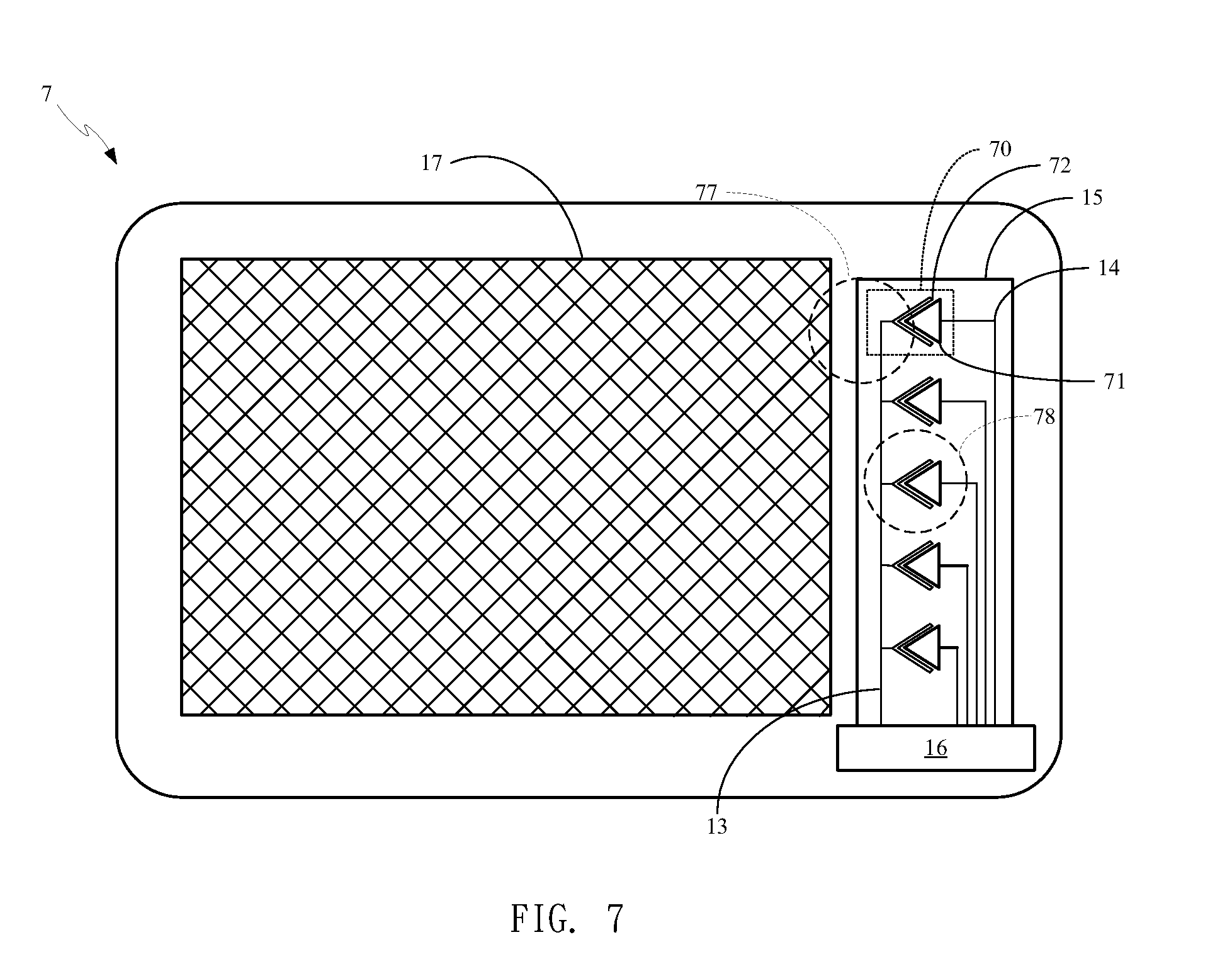
[0023] FIG. 7 is a schematic diagram illustrating a capacitive sensor in accordance with a fourth embodiment of the present invention;
[0024] FIG. 8 is a schematic diagram illustrating a capacitive sensor in accordance with a fifth embodiment of the present invention;
[0025] FIG. 9 is a schematic diagram illustrating a capacitive sensor in accordance with a sixth embodiment of the present invention; and
[0026] FIG. 10 is a flowchart illustrating a detection method of a capacitive sensor in accordance with a ninth embodiment of the present invention.
DETAILED DESCRIPTION OF THE PREFERRED EMBODIMENTS
[0027] Some embodiments of the present invention are described in details below. However, in addition to the descriptions given below, the present invention can be applicable to other embodiments, and the scope of the present invention is not limited by such, rather by the scope of the claims. Moreover, for better understanding and clarity of the description, some components in the drawings may not necessary be drawn to scale, in which some may be exaggerated relative to others, and irrelevant parts are omitted.
[0028] According to a first embodiment of the present invention, a capacitive sensor is provided, which may include one first conductive line, at least a second conductive line, at least a reference plate, at least a detecting plate, a controller and a shielding line. The at least one detecting plate defines (or segments) at least a space, and all reference plates are electrically coupled to the first conductive line. In addition, each detecting plate is electrically coupled to a second conductive line. Moreover, the controller provides electrical signals to the first conductive line and every second conductive lines, and the difference between signals of each second conductive line and the first conductive line is used for determining whether each detector is approached or touched by an external object.
[0029] As shown in FIG. 1, a capacitive sensor 1 includes a first conductive line 13, at least a second conductive line 14, at least a detector 10 and a controller 16, wherein each detector 10 includes a detecting plate 11 and a reference plate 12. The reference plate 12 is in an inverted U shape which defines a space. The detecting plate 11 is within this space, and electrically coupled to a second conductive line 14. Although there are three detectors 10 shown in FIG. 1, one with ordinary skill in the art can appreciate that the number of detectors is not limited to three.
[0030] In an example of the present invention, a capacitive sensor includes at least a detector. Each detector includes a detecting plate and at least one reference plate. The at least one reference plate defines a space, in which the detecting plate resides.
[0031] As shown in FIG. 2, a capacitive sensor 2 includes a first conductive line 13, at least a second conductive line 14, at least a detector 20 and a controller 16, wherein each detector 20 includes a detecting plate 21 and two reference plates 22. The two reference plates 22 and the first conductive line 13 together define a space. The detecting plate 21 resides within this space, and electrically coupled to a second conductive line 14. The space can be regarded as defined by the two reference plates 22 and the first conductive line 13. Although there are three detectors 20 shown in FIG. 2, one with ordinary skill in the art can appreciate that the number of detectors 20 is not limited to three.
[0032] In another example of the present invention, the capacitive sensor includes multiple spaces defined by at least one reference plate, and all reference plates are electrically coupled to a first conductive line. Each detecting plate is in a space and electrically coupled to a respective second conductive line. For example, adjacent detecting plates are separated by one or more reference plates.
[0033] As shown in FIG. 3, a capacitive sensor 3 includes four spaces defined by one reference plate 32 or four reference plates 32 (e.g. one integral reference plate or four individual reference plates connected together). Each space is provided with a detecting plate 31.
[0034] Alternatively, as shown in FIG. 3, a capacitive sensor 4 includes multiple spaces defined by one reference plate 42 or multiple reference plates 42 (e.g. one integral reference plate or multiple individual reference plates connected together). Each space is provided with a detecting plate 41.
[0035] In addition, in FIGS. 1 to 4, a shielding line 15 generally surrounds the first conductive line 13, the at least one second conductive line 14, the at least one reference plate (12, 22, 32, 42) and the at least one detecting plate (11, 21, 31, 41), and is electrically coupled to the controller 16. In an example of the present invention, the first conductive line 13 and the all the second conductive lines 14 are arranged in parallel to the controller 16. The shielding line 15 can be composed of one or more lines, arranged at either side of the first conductive line 13 and all of the second conductive lines 14. In another example of the present invention, there are two shielding lines 15 arranged in parallel at either side of the first conductive line 13 and all of the second conductive lines 14.
[0036] In an example of the present invention, the first conductive line 13 and at least one second conductive line 14 are connected to the controller 16 in parallel. For example, portions of the first conductive line 13 and at least one second conductive line 14 are arranged in parallel on a flat printed circuit board or a soft cable. In addition, the shielding line 15 (one or two lines) is/are arranged at either side of the first conductive line 13 and at least one second conductive line 14. In an example of the present invention, the shielding line 15, the first conductive line 13 and at least one second conductive line 14 are provided with the same electrical signal simultaneously. As such, when there is no external object, both sides of each conductive line of the first conductive line 13 and the at least one second conductive line 14 have symmetric electric field. Thus, when there is no external object, there are symmetric electric fields at both sides of the portions of the first conductive line 13 and the at least one second conductive line 14 that are connected to the controller 16 in parallel. In another example of the present invention, the shielding line 15 can also be provided with a DC potential, e.g. grounded. In yet another example of the present invention, the shielding line 15 can be provided with the same electrical signal as the first conductive line 13.
[0037] One with ordinary skill in the art can appreciate that the shapes of the detecting plates of the present invention are not limited to square, rectangle, fan, triangle, circle, ellipse, polygon, or other geometric shapes.
[0038] In an example of the present invention, the electrical signal provided to the first conductive line and the second conductive line can be a pulse width modulated (PWM) signal or other types of AC signals, such as a sine wave; the present invention is not limited as such. The electrical signal can be continuously provided. In an example of the present invention, the electrical signal can be continuously provided at intermittent intervals. In an example of the present invention, the electrical signal can be continuously provided continually.
[0039] In addition, the controller can detect capacitive coupling of the conductors of the first and second conductive lines through an integrator to determine the magnitude of the signals or the magnitude of the changes in the signals. One with ordinary skill in the art can appreciate that the signal difference can also be generated by other elements such as a subtractor, and regardless of whether it is in analog or digital form; the present invention is not limited as such.
[0040] Although in the above descriptions, the first conductive line is electrically coupled to the reference plates, the present invention is not limited to the first conductive line being electrically coupled to the reference plates, it can be electrically coupled to one of the above multiple detecting plates. In other words, the reference plates can be provided with the abovementioned electrical signal by other circuits, and the first conductive line and each of the second conductive lines are electrically coupled to one of the multiple detecting plates, respectively.
[0041] FIG. 5 is a detection method of a capacitive sensor according to a second embodiment of the present invention. First, in step 510, a first conductive line 13 and a plurality of second conductive lines 14 are provided. Then, in step 520, an electrical signal is continuously provided to the first conductive line 13 and each of the second conductive lines 14. In addition, in step 530, each time the electrical signal is provided, based on a signal difference between each second conductive line 14 and the first conductive line 13, the signal of each second conductive line 14 is identified as belonging to a first type or a second type.
[0042] In an example of the present invention, steps 520 and 530 can be carried out by the above controller 16. The first conductive line 13 and each second conductive line 14 provided in step 510 are electrically coupled to at least one conductor, respectively. The total dimension of the at least one conductor electrically coupled with the first conductive line 13 substantially equals to the total dimension of the at least one conductor electrically coupled with each second conductive line 14. For example, in FIGS. 1 to 4, the first conductive line 13 is electrically coupled to multiple reference plates 12, 22, 32 and 42, and each second conductive line 14 is electrically coupled to one detecting plate 11, 21, 31 and 41. One with ordinary skill in the art can appreciate that the detecting plate 11 can be composed of multiple sub-detecting plates, and each second conductive line 14 may be electrically coupled to the multiple sub-detecting plates. In an example of the present invention, the at least one conductor electrically coupled with the first conductive line 13 defines a plurality of spaces, and the at least one conductor electrically coupled with each second conductive line 14 resides in one of these spaces.
[0043] Since the total dimension of the at least one conductor electrically coupled with the first conductive line 13 substantially equals to the total dimension of the at least one conductor electrically coupled with each second conductive line 14, when there is no external object touching or approaching any of the conductors, the signals of the first conductive line 13 and each second conductive line 14 will be substantially equal to each other. In an example of the present invention, an insulating layer can be overlaid above all of the conductors. The insulating layer can be transparent or opaque, such as a transparent glass or film. When there is an external object approaching or touching the capacitive sensor, it may be approaching or touching the insulating layer.
[0044] The external object can be physically or virtually grounded, and can, for example, be a body part (e.g. a finger) of a human standing on the ground. When the external object touches or approaches a conductor, the amount of change in the conductor's signal varies with the distance and area approached by the external object. Thus, when an external object simultaneously approaches or touches a detecting plate and a portion of a reference plate, the area of the detecting plate approached or touched by the external object will be relatively larger than the area of the reference plate approached or touched by the external object. In other words, the amount of change in signal of the second conductive line 14 electrically coupled to the detecting plate approached or touched by the external object will be greater than the amount of change in signal of the first conductive line 13 (electrically coupled to all reference plates). On the contrary, the amount of change in signal of the second conductive line 14 not electrically coupled to the detecting plate approached or touched by the external object will be less than the amount of change in signal of the first conductive line 13. Therefore, according to the signal of the second conductive line 14 electrically coupled to the detecting plate approached or touched by the external object and the signal of the first conductive line 13, a detecting plate can be determined as being approached or touched by an external object (e.g. one of the first and second types) or not approached or touched by any external object (e.g. the other of the first and second types).
[0045] For example, the touch or approach of the external object will cause the signal to be reduced. Thus, the difference between the signals of each second conductive line 14 and the first conductive line 13 can be used to determine whether the detecting plate to which each second conductive line 14 electrically coupled is being approached or touched. For example, if the difference between signals is greater or less than a threshold, then it indicates the approach or touch of an external object. Alternatively, the signal difference at the time when there is no external object can be used as the reference. For example, the signal difference detected in an initial period is used as the signal difference when there is no external object approaching or touching the capacitive sensor, and is compared with the signal difference detected at subsequent multiple continuous detecting periods. When the difference between the signal differences of the initial period and the detecting period is greater or less than a threshold, then it indicates the approach or touch of an external object. In an example of the present invention, when the difference between signals exceeds a preset range or when the difference between the signal differences of the initial period and the detecting period exceeds a preset range, then it indicates the approach or touch of an external object; else, it indicates no external object. The preset range can be less or greater than a threshold.
[0046] In an example of the present invention, the sign (i.e. positive or negative) of the difference between signals or the difference between the signal differences of the initial and the detecting periods can be used for determining whether it belongs to the first type or the second type. For example, when the difference between the signal of the first conductive line 13 and a second conductive line 14 is a positive value, then this second conductive line 14 belongs to one of the first and second types, whereas when the difference between the signal of the first conductive line 13 and a second conductive line 14 is a negative value, then this second conductive line 14 belongs to the other of the first and second types.
[0047] Therefore, when some of the detecting plates are approached or touched while some are not, a conductive plate electrically coupled to at least one second conductive line 14 will be identified as belonging to the first type, while another conductive plate electrically coupled to at least one second conductive line 14 will be identified as belonging to the second type, wherein a conductor electrically coupled to the first conductive line 13 is touched or approached by the external object.
[0048] By comparing the signals of each second conductive line 14 with the first conductive line 13 in the capacitive sensor of the present invention, one or more detecting plates touched or approached by external object(s) can be determined. The comparison of signals of the two can be made by using a comparator, or the comparison of the difference between the signal differences of the two can be made by a differential amplifier. Furthermore, the signals of the two can be converted into a digital difference before comparing, or the signals of the two can be converted into digital values before comparing. The present invention includes but is not limited to these comparison methods, and one with ordinary skill in the art can recognize that there are other ways of comparing signals, which will not be further described herein.
[0049] The capacitive sensor of the present invention can be used in keypad application, as shown in FIGS. 1 and 2. For example, each detecting plate can correspond to an independent keypad. The capacitive sensor of the present invention can simultaneously detect the pressing of multiple keypads. Keypads can also be designed as arrow keys, such as that shown in FIG. 3, wherein there are four arrow keys, namely, up, right, down and left arrow keys. One with ordinary skill in the art can appreciate arrow keys in other directions, such as eight-directional arrow keys, or multi-directional arrow keys, such as that shown in FIG. 4, which forms a ring-shaped multi-directional arrow keys used in applications such as a jog dial.
[0050] In an example of the present invention, there can be a compound-type capacitive sensing device, for example, with multiple sets of capacitive sensors. Each capacitive sensor includes the abovementioned first conductive line, the at least one second conductive line, the at least one reference plate, the at least one detecting plate, the controller and the shielding line. The at least one detecting plate defines (or segments) at least one space, and all of the reference plates are electrically coupled to the first conductive line. Moreover, each detecting plate is electrically coupled to a second conductive line. In addition, the controller provides an electrical signal to the first conductive line and each of the second conductive line. According to the signal difference between each of the second conductive line and the first conductive line, it can be determined whether each detector is approached or touched by an external object. As such, all of the detecting plates form a detecting plate matrix.
[0051] These capacitive sensors can have their own independent first conductive line 13 and second conductive lines 14, and are directly connected to the controller 16 or jointly connected to the conductive line of the controller 16 and controlled by a switching circuit, wherein at any one time, the first conductive line 13 and the second conductive lines 14 of only one capacitive sensor are electrically coupled to the controller 16.
[0052] FIG. 6 is a detection method for a capacitive sensor using signal differences according to a third embodiment of the present invention. First, in step 610, a reference value and multiple detection values are provided continuously in multiple periods, and in step 620, one of these periods is regarded as an initial period, while other periods are regarded as detection periods. For example, the first period is regarded as the initial period, or any one period can be regarded as the initial period. Steps 610 and 620 can be repeated.
[0053] Next, in step 630, in the initial period, the difference between each detection value and the reference value is recorded as an initial difference for each detection value. In each detection periods, the difference between each detection value and the reference value is recorded as a detection difference for each detection value. Moreover, in step 650, in each detection period, each detection value for which the detection difference is greater or less than the initial difference by a threshold is identified as one of a first type and a second type, whereas each detection value for which the detection difference is not greater or not less than the initial difference by a threshold is identified as the other of the first type and the second type. Steps 630, 640 and 650 can be performed iteratively along with steps 610 and 620. In addition, steps 610 to 650 can be carried out by the above controller 16.
[0054] The aforementioned method can be applied to a capacitive sensor that performs detection using signal difference. The capacitive sensor may include: a first conductive line; at least one second conductive line; at least one reference plate defining at least one space, wherein all reference plates are electrically coupled to the first conductive line; at least one detecting plate, each resides in one of the at least one space and is electrically coupled to one of the at least one second conductive line; and a controller. It performs at least the following operations of: continuously providing an electrically signal to the first conductive line and each second conductive line in multiple periods to obtain a reference value and multiple detection values; regarding one of these periods as an initial period, and the other periods as detection periods; in the initial period, recording the difference between each detection value and the reference value as an initial difference for each detection value; in each detection periods, recording the difference between each detection value and the reference value as a detection difference for each detection value; and in each detection period, identifying each detection value for which the detection difference is greater or less than the initial difference by a threshold as one of a first type and a second type, and identifying each detection value for which the detection difference is not greater or not less than the initial difference by a threshold as the other of the first type and the second type.
[0055] In an example of the present invention, the reference value is generated based on the signal of at least one reference plate. The at least one reference plate defines a plurality of spaces. Each detection value is generated based on the signal of one of a plurality of detecting plates, each detecting plates resides in one of these spaces.
[0056] In another example of the present invention, if each detection value identified as the first type has a detection difference greater than the initial difference, then each detection value identified as the second type has a detection difference less than the initial difference. On the contrary, if each detection value identified as the first type has a detection difference less than the initial difference, then each detection value identified as the second type has a detection difference greater than the initial difference. For example, in some detection periods, the reference value and the at least one detection value are changed, both changed to larger values or a smaller values, wherein the amount of change in the at least one detection value is significantly larger than that in the reference value, resulting in the detection difference for the at least one detection value to become larger or smaller. On the contrary, the detection differences for other detection values will have the opposite changes.
[0057] One with ordinary skill in the art can appreciate that the reference value and each detection value are not necessarily substantially equal to each other at the initial period, i.e. they can be substantially equal to each other or not. Similarly, one with ordinary skill in the art can appreciate that the dimensions of the conductors electrically coupled to the first conductive line and each second conductive line can be substantially equal to each other or not; the present invention includes but is not limited to the dimensions of the conductors electrically coupled to the first conductive line and each second conductive line being the same.
[0058] In addition, the above first and second types may represent two states with one indicates status change, while the other indicates no status change. For example, the first type may indicate that the conductor is touched or approached by an external object or a signal changed as a result of this, whereas the second type may indicate that the conductor is not touched or approached by an external object or a signal is not changed. Moreover, it can be applied to switches, for example, when the reference value exceeds a threshold, and the amount of change in at least one detection value is significantly larger than that in the reference value, the detection difference for a detection value not changed will be greater than a threshold, which can be used for detecting the detection value not changed, and as one of on and off states, while the other detection values are used as the other one of on and off states.
[0059] Referring to FIG. 7, a capacitive sensor 7 provided according to a fourth embodiment of the present invention is shown. The capacitive sensor 7 includes multiple reference plates 72 and multiple detecting plates 71. In addition, the present embodiment further includes a touch sensor 17 adjacent to the capacitive sensor 7. Although five detectors 70 are illustratively shown as an example, one with ordinary skill in the art can appreciate that the number of detectors includes but is not limited to five. When an external object approaches or touches the touch sensor 17, the touch sensor 17 can provide sensing information of the location of the external object for interpreting into the location of the external object. For example, the sensing information can be received by the controller 16 for determining the location of the external object. One with ordinary skill in the art can appreciate that the touch sensor 17 can be capacitive, resistive, surface-acoustic-wave type, infrared, optical and the like, wherein the detection method for the corresponding sensing information is prior art, and thus will not be further explained.
[0060] In an example of the present invention, the area of one side of detecting plates 71 facing the touch sensor 17 is smaller than that of the other side, wherein the area of the side facing the touch sensor 17 and the area of the other side can be areas among a range with the same width between the two sides. For example, the detecting plates 71 can be triangular, wherein one angle points towards the touch sensor 17 as shown in FIG. 7. Alternatively, for example, the side facing the touch sensor 17 can be of an arc shape, such as a semi-circle or a semi-ellipse.
[0061] The area of the side of the detecting plates 71 facing the touch sensor 17 depends on the distance between the detecting plates 71 and the touch sensor 17.
[0062] For example, when an external object simultaneously approaches or touches the touch sensor 17 and a detecting plate 71 as shown by a touch range 77 in FIG. 7, the area of the detecting plate 71 touched or approached by the external object is very small, such that the above difference between signals or the difference between the signal differences in the initial period and the detection period may not exceed the preset range, and no valid touch is determined. On the contrary, when an external object approaches or touches mostly a detecting plate 71 as shown by a touch range 78 in FIG. 7, the above difference between signals or the difference between the signal differences in the initial period and the detection period is then enough to exceed the preset range. As such, problems associated with accidental touching when the capacitive sensor 7 and the touch sensor 17 are in close proximity to each other can be lessened.
[0063] In the above descriptions, the phrase "the dimensions of two substantially equal to each other" means that the dimensions of these two are the same or substantially the same, for example, the difference between the two is within 10%, e.g. one is greater than the other by 10%. The total dimension of at least one conductor electrically coupled with the first conductive line 13 being substantially equal to the total dimension of at least one conductor electrically coupled with each second conductive line 14 means that difference between the total dimension of at least one conductor electrically coupled with the first conductive line 13 and the total dimension of at least one conductor electrically coupled with each second conductive line 14 is within 10%.
[0064] In the above descriptions, self-capacitive detection is employed, wherein the difference between signals of the first conductive line and the second conductive line provided with the electrical signal is used for the determination of an external object. In a capacitive sensor provided according to the present invention, the difference between signals of the detecting plates is used for the determination.
[0065] Referring to FIG. 8, a capacitive sensor 8 proposed according to a fifth embodiment of the present invention is shown. A first conductive line 13 is electrically coupled to one detecting plate 21, and reference plates 22 are provided with an electrical signal by a third conductive line 18. In addition, referring to FIGS. 5 and 6 and their associated descriptions for the determination based on the difference between signals of the first conductive line 13 and the second conductive line 14 provided with the electrical signal, and this will not be described again.
[0066] The present embodiment can also be applied to FIGS. 1, 2, 3, 4 and 7, except that the first conductive line is no longer used for comparing signal difference with the second conductive lines, but simply used for providing the electrical signal. The comparison of signal difference is performed between each detecting plate and another detecting plate, that is, between each second conductive line and another second conductive line. In an example of the present invention, the determination is based on the difference between signals of each second conductive line and a referenced second conductive line, as shown in FIG. 8. For example, the first one or the last one of the second conductive lines is used as the referenced second conductive line for generating a signal difference with every other second conductive line to determine whether the detecting plate electrically coupled with the every other second conductive line is touched or approached by an external object. Assuming that the interference of the noise coming from a display on each detecting plate substantially equal to each other, generating signal difference from a pair of signals can effectively suppress the noise from the display.
[0067] Assuming there are detecting plates a, b and c, and signal differences Sa-b and Sa-c are generated based on the above, which detecting plate(s) is being touched or approached by external object(s) can be determined according to the following table.
TABLE-US-00001 TABLE 1 Detecting plate(s) being touched Sa-b Sa-c none or (a, b and c) 0 0 a - - b + 0 c 0 + a & b 0 - a & c - 0 b & c + +
[0068] "+", "-" and "0" shown in Table 1 indicates that the signal difference is a positive value, a negative value and null, respectively. In actual practice, signals of the detecting plates will vary due to the influence of the environment, so there may be error. In view of this, "+", "-" and "0" can be regarded as positive values that are greater than a null range, negative values that are less than the null range, and values that fall within the null range. Alternatively, "+", "-" and "0" can be regarded as positive values that are greater than a positive threshold value, negative values that are less than a negative threshold value, and values that fall within a null range. The example in Table 1 is shown having a lookup table with three detecting plates, but one with ordinary skill in the art can appreciate that lookup tables with four, five or more.
[0069] In addition to determining directly from the signal difference, the amount of change in the signal difference may also be used for determination. For example, each signal difference under no presence of an external object is used as the baseline for comparison in each of the subsequent detections so as to determine the amount of change of each signal difference. Thus, Sa-b and Sa-c in the previous example can be replaced by the amount of change in signal differences .DELTA.Sa-b and .DELTA.Sa-c.
[0070] The above signal difference can be the signal difference between each detecting plate with one specific detecting plate, or between each detecting plate and a preceding detecting plate, or between each detecting plate and a following detecting plate.
[0071] When there are N detecting plates, there are N-1 signal differences between detecting plates and the preceding (or following) detecting plates. Thus, the amount of change in signal difference is N-1 continuous amounts of change in signal difference. In the following descriptions, the amount of change in signal difference is used for illustration, but signal difference instead of the amount of change in signal difference is also applicable.
[0072] The above continuous amounts of change in signal difference can be used to recover the amounts of change in signals of the detecting plates. For example, each amount of change in signal difference is added to (or subtracted from) the sum of all preceding (or following) amounts of change in signal differences to generate a plurality of continuous amounts of change in signal. For example, there are N-1 amounts of change in signal difference, so each amount of change in signal difference is added to the sum of all preceding amounts of change in signal differences to generate N-1 amounts of change in signal. Since there is no amount of change in signal difference preceding the first amount of change in signal difference, so it is assumed that the amount of change in signal preceding the first amount of change in signal is null, which is regarded as the 0.sup.th amount of change in signal. As such, N amounts of change in signal can be generated corresponding to the above N detecting plates.
[0073] The first to the N-1.sup.th amounts of change in signal correspond to the amount of change of the amount of change of the 0.sup.th signal. Assuming that the above N detecting plates are the 0.sup.th, 1.sup.st . . . N-1.sup.th detecting plates, they correspond to the 0.sup.th, 1.sup.st, . . . N-1.sup.th amount of change in signal, respectively, and the 0.sup.th amount of change in signal is null.
[0074] Assuming a small range around zero as the center is the null range, any amount of change in signal that falls within this null range is regarded as within the error range of null. When no external object is touching or approaching the 0.sup.th detecting plate, other amount of change in signal corresponding to no touch/approach will fall within the null range, while the amount of change in signal corresponding to a touch/approach will be a positive or negative value outside the null range. In order to facilitate the following descriptions, in this example, the amount of change in signal corresponding to a touch/approach is a positive value. On the contrary, when an external object is touching or approaching the 0.sup.th detecting plate, the amount of change in signal corresponding to a touch/approach will fall within or close to the null range, while the amount of change in signal corresponding to no touch/approach will be a negative value.
[0075] Assuming there are detecting plates a, b and c, the signal differences generated as mentioned before are .DELTA.Sa-b and .DELTA.Sb-c can be used for determining which detecting plate(s) is touched/approached by an external object.
[0076] Obviously, the amount of change in signal representing a touch/approach will be greater than the smallest amount of change in signal and greater than a threshold. In an example of the present invention, the controller determines that a detecting plate is approached by an external object based on comparison of the amount of change in signal with a threshold greater than the smallest amount of change in signal. For example, if detecting plates b and c are touched/approached by external object(s), then the amounts of change in signal difference .DELTA.Sa-b and .DELTA.Sb-c will be "+" and "0", respectively, and the amounts of change in signal .DELTA.Sa, .DELTA.Sb and .DELTA.Sc recovered from the amounts of change in signal difference .DELTA.Sa-b and .DELTA.Sb-c are "0", "+" and "+", respectively, thereby determining detecting plates b and c are touched/approached by external object(s).
[0077] In another example of the present invention, a detecting plate is determined to be approached by an external object if the amount of change in signal is greater than the smallest amount of change in signal by a threshold. Alternatively, when the amount of change in at least one signal is less than a negative threshold, a detecting plate is determined to be approached by an external object if the amount of change in signal is greater than this negative threshold. Alternatively, a detecting plate is determined to be approached by an external object if the amount of change in signal is greater than a positive threshold. For example, if detecting plates a and b are touched/approached by external object(s), then the amounts of change in signal difference .DELTA.Sa-b and .DELTA.Sb-c will be "0" and "-", respectively, and the amounts of change in signal .DELTA.Sa, .DELTA.Sb and .DELTA.Sc recovered from the amounts of change in signal difference .DELTA.Sa-b and .DELTA.Sb-c are "0", "0" and "-", respectively. Since the smallest one of the three is "-", and assuming that "0" is greater than "-" by a threshold, then it can be determined that detecting plates a and b are touched/approached by external object(s) by "0" as the amounts of change in signal .DELTA.Sa and .DELTA.Sb.
[0078] In still another example of the present invention, an average of all signals is used as the determination basis. The controller determines a detecting plate is approached by an external object if the amount of change in signal is greater than the determination basis or greater than the determination basis by a threshold. In other words, an amount of change in signal greater than a positive (or negative) threshold indicates a detecting plate is touched or approached by an external object. Accordingly, one can determine a detecting plate is touched or approached by an external object regardless of whether the smallest amount of change in signal is "0" or "-".
[0079] Referring to FIG. 9, a capacitive sensor 9 proposed by a sixth embodiment of the present invention is shown. The reference plates are provided with the electrical signal by the third conductive line 18, and each detecting plate 21 is electrically coupled to a fourth conductive line 19. The fourth conductive lines 19 coupled to the detecting plates 21 are arranged sequentially in the order of the detecting plates 21. The signal difference between each fourth conductive line 19 and an adjacent fourth conductive line 19 is used for determination, for example, the signal difference between each fourth conductive line 19 and an immediately preceding fourth conductive line 19 is used for determination, or the signal difference between each fourth conductive line 19 and an immediately following fourth conductive line 19 is used for determination. In other words, FIG. 9 employs mutual capacitive coupling to generate signals on the fourth conductive lines 19.
[0080] Accordingly, in an example of the present invention, the capacitive sensor includes a plurality of sequentially arranged detecting plates, at least one reference plate and a controller. The at least one reference plate is disposed between the detecting plates in a manner such as those shown in FIGS. 1, 2, 3, 4, 7, 8 and 9. In addition, the controller simultaneously provides an electrical signal to the at least one reference plate and each detecting plate, and determines if at least one detecting plate is touched or approached by at least one external object based on the signal difference between each detecting plate and another detecting plate. Moreover, the controller determines if at least one detecting plate is touched or approached by at least one external object based on the amount of change in signal difference before and after the touch/approach by the at least one external object.
[0081] Accordingly, a seventh embodiment of the present invention is a capacitive sensor, which includes a plurality of sequentially arranged detecting plates; at least one reference plate disposed between the detecting plates; a memory for storing a lookup table that defines corresponding relationships between a plurality of signal differences or amounts of change in signal difference and the detecting plate(s) being touched/approached; and a controller. The controller simultaneously provides an electrical signal to each detecting plate, and provides the electrical signal or a DC potential to the at least one reference plate, or the controller simultaneously provides an electrical signal to each reference plate so that the signal difference or the amount of change in signal difference is generated by subtraction between signals of each detecting plate and another detecting plate. Furthermore, the controller determines if at least one detecting plate is touched or approached by at least one external object by using the lookup table based on the signal differences.
[0082] In an example of the present invention, the controller designates one of the detecting plates as the specific detecting plate, and each signal difference or the amount of change in signal difference is generated by subtraction between signals from one of non-specific detecting plates and the specific detecting plate. In another example of the present invention, each signal difference or the amount of change in signal difference is generated by subtraction between signals from one of the detecting plates and a preceding detecting plate.
[0083] A eighth embodiment of the present invention is a capacitive sensor, which includes a plurality of sequentially arranged detecting plates; at least one reference plate disposed between the detecting plates to separate each detecting plate; and a controller. The controller simultaneously provides an electrical signal to each detecting plate, and provides the electrical signal or a DC potential to the at least one reference plate, so that a signal difference is generated by subtraction between signals from each of the detecting plate and a preceding detecting plate, and the signal differences are combined to form a plurality of continuous signal differences. Moreover, the controller adds each signal difference of the continuous signal differences to all the preceding or following signal differences to generate a plurality of continuous recovered signal values, and determines if at least one detecting plate is touched or approached by at least one external object based on the continuous recovered signal values.
[0084] The continuous recovered signal values further include an additionally added zero. Each of the continuous recovered signal values correspond to one of the detecting plates, respectively. The recovered signal values can be the above recovered signals or the recovered amount of change in signal. In an example of the present invention, a detecting plate corresponding to a recovered signal value that exceeds the smallest among the continuous recovered signal values by a threshold is determined to be touched or approached by an external object. In another example of the present invention, the controller further includes generating an average of the continuous recovered signal values, wherein a detecting plate corresponding to a recovered signal value that exceeds the average is determined to be touched or approached by an external object. In still another example of the present invention, a memory for storing a lookup table is further included, wherein the lookup table defines the corresponding relationships between the continuous recovered signal values and detecting plate(s) being touched or approached, and the controller determines if at least one detecting plate is touched or approached by at least one external object by using the lookup table based on the continuous recovered signal values.
[0085] Some operations of the controller mentioned before can be achieved by a processor in cooperation with software. Thus, in an example of the present invention, a capacitive sensor includes: a plurality of sequentially arranged detecting plates; at least one reference plate disposed between the detecting plates to separate each detecting plate; a means for simultaneously providing an electrical signal to each detecting plate and providing the electrical signal or a DC potential to the reference plate; a means for generating a signal difference by subtraction between signals from each of the detecting plate and a preceding detecting plate and combining the signal differences to form a plurality of continuous signal differences; a means for adding each signal difference of the continuous signal differences to all the preceding or following signal differences to generate a plurality of continuous recovered signal values; and a means for determining if at least one detecting plate is touched or approached by at least one external object based on the continuous recovered signal values.
[0086] Referring to FIG. 10, a detection method of a capacitive sensor proposed by a ninth embodiment of the present invention is shown. First, in step 1010, a plurality of sequentially arranged detecting plates and at least one reference plate are provided, the at least one reference plate is disposed between the detecting plates to separate each detecting plate. Next, in step 1020, an electrical signal is simultaneously provided to each detecting plate and the electrical signal or a DC potential is provided to the reference plate, or an electrical signal is simultaneously provided to each reference plate. Then, in step 1030, a signal difference is generated by subtraction between signals from each of the detecting plate and a preceding detecting plate, and the signal differences are then combined to form a plurality of continuous signal differences. Next, in step 1040, each signal difference of the continuous signal differences is added to all the preceding or following signal differences to generate a plurality of continuous recovered signal values. Then, in step 1050, it is determined whether at least one detecting plate is touched or approached by at least one external object based on the continuous recovered signal values. Other details of this embodiment are already disclosed in previous descriptions, and will not be described further.
[0087] In the above descriptions, there are two kinds of detections, namely self capacitive detection and mutual capacitive detection. In self capacitive detection, an electrical signal is simultaneously provided to each detecting plate and the electrical signal or a DC potential is provided to the reference plates. In mutual capacitive detection, an electrical signal is simultaneously provided to each reference plate. The reference plate is disposed between the detecting plates for separating them. For example, there might be other circuits underneath the capacitive sensor, if there is no reference plate, then capacitive coupling between some of the detecting plates and the circuits underneath may cause signal changes, such that the signal differences are not null even when there is no presence of any external object. On the contrary, if one can ensure that said problem will not happen, then the reference plate is not necessarily needed.
[0088] In other words, in the case of no reference plate, self capacitive detection is employed, wherein an electrical signal is simultaneously provided to each detecting plate.
[0089] The above embodiments are only used to illustrate the principles of the present invention, and they should not be construed as to limit the present invention in any way. The above embodiments can be modified by those with ordinary skill in the art without departing from the scope of the present invention as defined in the following appended claims.
* * * * *
D00000
D00001
D00002
D00003
D00004
D00005
D00006
D00007
XML
uspto.report is an independent third-party trademark research tool that is not affiliated, endorsed, or sponsored by the United States Patent and Trademark Office (USPTO) or any other governmental organization. The information provided by uspto.report is based on publicly available data at the time of writing and is intended for informational purposes only.
While we strive to provide accurate and up-to-date information, we do not guarantee the accuracy, completeness, reliability, or suitability of the information displayed on this site. The use of this site is at your own risk. Any reliance you place on such information is therefore strictly at your own risk.
All official trademark data, including owner information, should be verified by visiting the official USPTO website at www.uspto.gov. This site is not intended to replace professional legal advice and should not be used as a substitute for consulting with a legal professional who is knowledgeable about trademark law.