Inductive Downhole Tool Having Multilayer Transmitter And Receiver And Related Methods
San Martin; Luis E. ; et al.
U.S. patent application number 13/499739 was filed with the patent office on 2012-12-27 for inductive downhole tool having multilayer transmitter and receiver and related methods. This patent application is currently assigned to HALLIBURTON ENERGY SERVICES, INC. Invention is credited to Michael S. Bittar, Evan L. Davies, Luis E. San Martin.
| Application Number | 20120326825 13/499739 |
| Document ID | / |
| Family ID | 43857039 |
| Filed Date | 2012-12-27 |


| United States Patent Application | 20120326825 |
| Kind Code | A1 |
| San Martin; Luis E. ; et al. | December 27, 2012 |
INDUCTIVE DOWNHOLE TOOL HAVING MULTILAYER TRANSMITTER AND RECEIVER AND RELATED METHODS
Abstract
A downhole tool including a transmitter coil assembly and a receiver coil assembly. The coil assembly includes at least one first coil having a first support member with a first single layer of wire wound therearound. The coil assembly further includes at least one second coil. The second coil includes a second support member having a second single layer of wire wound therearound. The first support member is disposed within the second support member, and the first single layer spaced apart from the second single wire by a distance of D.
| Inventors: | San Martin; Luis E.; (Houston, TX) ; Davies; Evan L.; (Spring, TX) ; Bittar; Michael S.; (Houston, TX) |
| Assignee: | HALLIBURTON ENERGY SERVICES,
INC Houston TX |
| Family ID: | 43857039 |
| Appl. No.: | 13/499739 |
| Filed: | October 9, 2009 |
| PCT Filed: | October 9, 2009 |
| PCT NO: | PCT/US09/60145 |
| 371 Date: | September 10, 2012 |
| Current U.S. Class: | 336/170 |
| Current CPC Class: | H01Q 1/04 20130101; E21B 47/01 20130101; G01V 3/28 20130101; H01Q 1/38 20130101 |
| Class at Publication: | 336/170 |
| International Class: | H01F 27/28 20060101 H01F027/28 |
Claims
1.-23. (canceled)
24. An apparatus comprising: at least one first coil including a first support member having a first single layer of wire extending along at least a portion of an outer periphery of the first support member; and at least one second coil including a second support member having a second single layer of wire extending along at least a portion of an outer periphery of the second support member, the second support member having an interior portion sized and shaped to receive the first support member therein, wherein the first support member is disposed within the second support member, wherein the first single layer is coaxial with and spaced apart from the second single layer by a distance of D, wherein one of the at least one first coil or the at least one second coil is capable of inducing eddy currents in a surrounding formation when driven by an oscillator, and wherein another one of the at least one first coil or the at least one second coil is capable of sensing the eddy currents induced in the surrounding formation.
25. The apparatus of claim 24, wherein the at least one first coil and the at least one second coil are wound around the outer periphery of the first and second support members, respectively.
26. The apparatus of claim 24, wherein at least one of the at least one first coil and the at least one second coil are wound on a helical path.
27. The apparatus of claim 24, wherein at least one of the first support member or the second support member include a groove therein, the groove receiving the first or the second single layer of wire therein, respectively.
28. The apparatus of claim 24, wherein the first single layer of wire is disposed substantially orthogonal to the second single layer of wire when the first single layer of wire and the second single layer of wire are each wound on helical paths.
29. The apparatus of claim 24, further comprising: a third single layer of wire wound over a third support member, the first support member and the second support member being disposed within the third support member.
30. A system comprising: a downhole tool including at least one first coil including a first support member having a first single layer of wire wound therearound; and at least one second coil including a second support member having a second single layer of wire wound therearound, the second support member having an interior portion sized and shaped to receive the first support member therein, wherein the first support member is disposed within the second support member, wherein the first single layer of wire is coaxial with and spaced apart from the second single layer of wire by a distance of D, wherein one of the at least one first coil or the at least one second coil is capable of inducing eddy currents in a surrounding formation when driven by an oscillator, and wherein another one of the at least one first coil or the at least one second coil is capable of sensing the eddy currents induced in the surrounding formation.
31. The system of claim 30, wherein at least one of the first support member or the second support member include a groove therein, the groove receiving the first or the second single layer of wire therein, respectively.
32. The system of claim 30, further comprising: a third single layer of wire wound over a third support member.
33. The system of claim 32, wherein the first single layer of wire is disposed substantially orthogonal to the second layer of wire, wherein the second layer of wire is disposed substantially orthogonal to the third layer of wire, and wherein each of the first, second, and third layers of wires are wound on a helical path.
34. The system of claim 30, wherein at least one of the first support member or the second support member comprises a mandrel associated with the downhole tool.
35. A method comprising: driving at least one first coil or at least one second coil to induce eddy currents in a surrounding formation, the at least one first coil including a first support member having a first single layer of wire extending along at least a portion of an outer periphery of the first support member, and the at least one second coil including a second support member having a second single layer of wire extending along at least a portion of an outer periphery of the second support member, the second support member having an interior portion sized and shaped to receive the first support member therein, wherein the first support member is disposed within the second support member, wherein the first single layer is coaxial with and spaced apart from the second single layer by a distance of D, wherein one of the at least one first coil or the at least one second coil is capable of inducing eddy currents in a surrounding formation when driven by an oscillator, and wherein another one of the at least one first coil or the at least one second coil is capable of sensing the eddy currents induced in the surrounding formation; and sensing the eddy currents in the surrounding formation by another one of the at least one first coil or the at least one second coil.
36. The method of claim 35, further comprising: sensing the eddy currents while a coil assembly comprising the at least one first coil and the at least one second coil are disposed in a drill string.
37. The method of claim 35, further comprising: sensing the eddy currents while a coil assembly comprising the at least one first coil and the at least one second coil are disposed in a wireline tool.
38. The method of claim 35, further comprising: operating the at least one first coil and the at least one second coil as transmitter coils or receiver coils.
Description
TECHNICAL FIELD
[0001] The application relates generally to inductive well logging. In particular, the application relates to inductive well logging with a multilayer inductive logging tool.
BACKGROUND
[0002] During drilling operations for extraction of hydrocarbons, an accurate determination of a shape of a borehole is important. In particular, a number of other downhole measurements are sensitive to a stand-off of the downhole tools from the formation. Knowledge of the borehole shape may be required to apply corrections to these downhole measurements. A determination of the shape of the borehole has various other applications. For example, for completing a well, an accurate knowledge of the borehole shape is important in hole-volume calculations for cementing.
BRIEF DESCRIPTION OF THE DRAWINGS
[0003] The embodiments are provided by way of example and not limitation in the figures of the accompanying drawings, in which like references indicate similar elements and in which:
[0004] FIG. 1 illustrates a perspective view of an induction coil assembly, according to example embodiments.
[0005] FIG. 2 illustrates a perspective view of an induction coil assembly, according to other example embodiments.
[0006] FIG. 3 illustrates an exploded perspective view of the coil assembly of FIG. 2.
[0007] FIG. 4A illustrates a drilling well during Measurement While Drilling (MWD) operations, Logging While Drilling (LWD) operations or Surface Data Logging (SDL) operations, according to some embodiments.
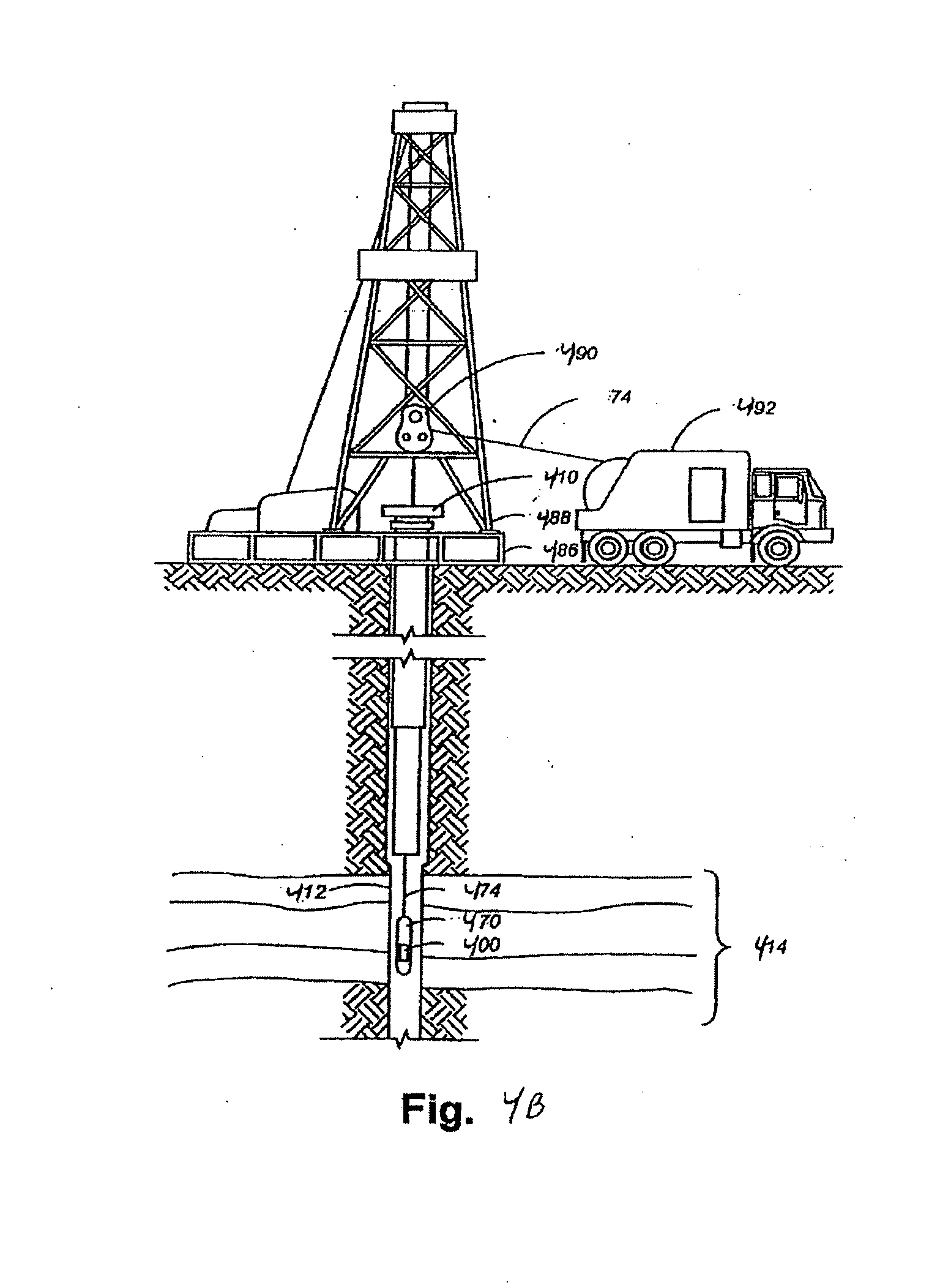
[0008] FIG. 4B illustrates a drilling well during wireline logging operations, according to some embodiments.
[0009] FIG. 5 illustrates a portion of an induction coil assembly, according to other example embodiments.
DETAILED DESCRIPTION
[0010] Methods; apparatus and systems for induction well logging are described. In the following description, numerous specific details are set forth. However, it is understood that embodiments of the invention may be practiced without these specific details. In other instances, well-known circuits, structures and techniques have not been shown in detail in order not to obscure the understanding of this description. Some embodiments may be used in Measurement While Drilling (MWD), Logging While Drilling (LWD) and wireline operations.
[0011] A method and system of using a downhole tool having an induction antenna coil on several layers of a support member such as a mandrel, which can be used to increase signal strength of small diameter tools. This further allows for additional coils to be used on the downhole tool with different orientations.
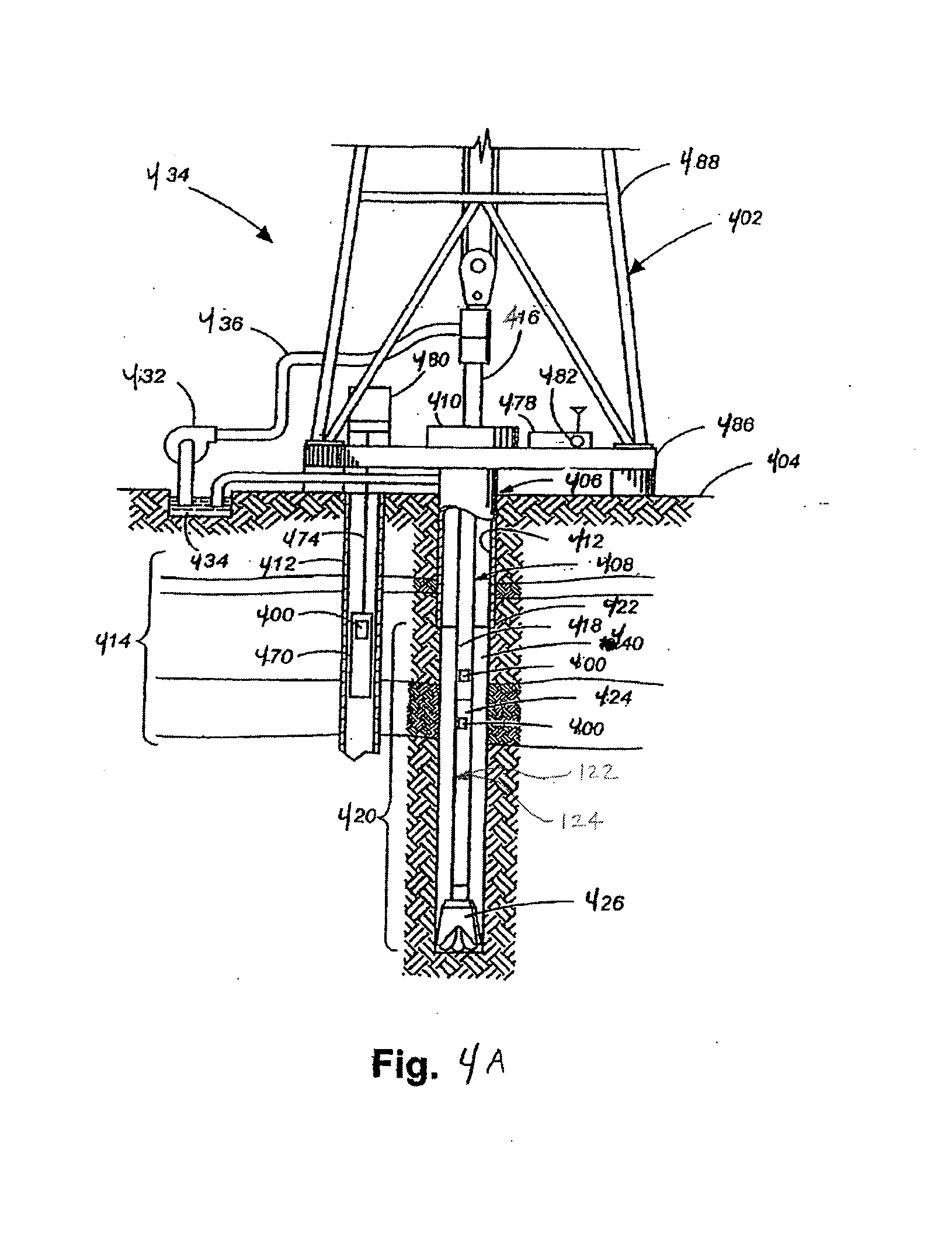
[0012] Examples of inductive downhole tools can be seen in FIGS. 4A and 4B. FIG. 4A illustrates a drilling well during Measurement While Drilling (MWD) operations, Logging While Drilling (LWD) operations or Surface Data Logging (SDL) operations, according to some embodiments. A system 464 may also form a portion of a drilling rig 402 located at a surface 404 of a well 406. The drilling rig 402 may provide support for a drill string 408. The drill string 408 may operate to penetrate a rotary table 410 for drilling a borehole 412 through subsurface formations 414. The drill string 408 may include a Kelly 416, drill pipe 418, and a bottom hole assembly 420, perhaps located at the lower portion of the drill pipe 418. The drill string 408 further includes one or more coils 120, including at least one transmitter coil 122 and/or at least one receiver coil 124, as further discussed below.
[0013] The bottom hole assembly 420 may include drill collars 422, a downhole tool 424, and a drill bit 426. The drill bit 426 may operate to create a borehole 412 by penetrating the surface 404 and subsurface formations 414. The downhole tool 424 may comprise any of a number of different types of tools including MWD (measurement while drilling) tools, LWD (logging while drilling) tools, and others.
[0014] During drilling operations, the drill string 408 (perhaps including the Kelly 416, the drill pipe 418, and the bottom hole assembly 420) may be rotated by the rotary table 410. In addition to, or alternatively, the bottom hole assembly 420 may also be rotated by a motor (e.g., a mud motor) that is located downhole. The drill collars 422 may be used to add weight to the drill bit 426. The drill collars 422 also may stiffen the bottom hole assembly 420 to allow the bottom hole assembly 420 to transfer the added weight to the drill bit 426, and in turn, assist the drill bit 426 in penetrating the surface 404 and subsurface formations 414.
[0015] During drilling operations, a mud pump 432 may pump drilling fluid (sometimes known by those of skill in the art as "drilling mud") from a mud pit 434 through a hose 436 into the drill pipe 418 and down to the drill bit 426. The drilling fluid can flow out from the drill bit 426 and be returned to the surface 404 through an annular area 440 between the drill pipe 418 and the sides of the borehole 412. The drilling fluid may then be returned to the mud pit 434, where such fluid is filtered. In some embodiments, the drilling fluid can be used to cool the drill bit 426, as well as to provide lubrication for the drill bit 426 during drilling operations. Additionally, the drilling fluid may be used to remove subsurface formation 414 cuttings created by operating the drill bit 426.
[0016] FIG. 4B illustrates a drilling well during wireline logging operations, according to some embodiments. A drilling platform 486 is equipped with a derrick 488 that supports a hoist 490. Drilling of oil and gas wells is commonly carried out by a string of drill pipes connected together so as to form a drilling string that is lowered through a rotary table 410 into a wellbore or borehole 412. Here it is assumed that the drilling string has been temporarily removed from the borehole 412 to allow a wireline logging tool body 470, such as a probe or sonde, to be lowered by wireline or logging cable 474 into the borehole 412. Typically, the tool body 470 is lowered to the bottom of the region of interest and subsequently pulled upward at a substantially constant speed. During the upward trip, instruments included in the tool body 470 may be used to perform measurements on the subsurface formations 414 adjacent the borehole 412 as they pass by. The measurement data can be communicated to a logging facility 492 for storage, processing, and analysis. The logging facility 492 may be provided with electronic equipment for various types of signal processing. Similar log data may be gathered and analyzed during drilling operations (e.g., during Logging While Drilling, or LWD operations). The wireline logging tool body 570 further includes one or more coils 120, including at least one transmitter coil 122 and at least one receiver coil 124, as further discussed below.
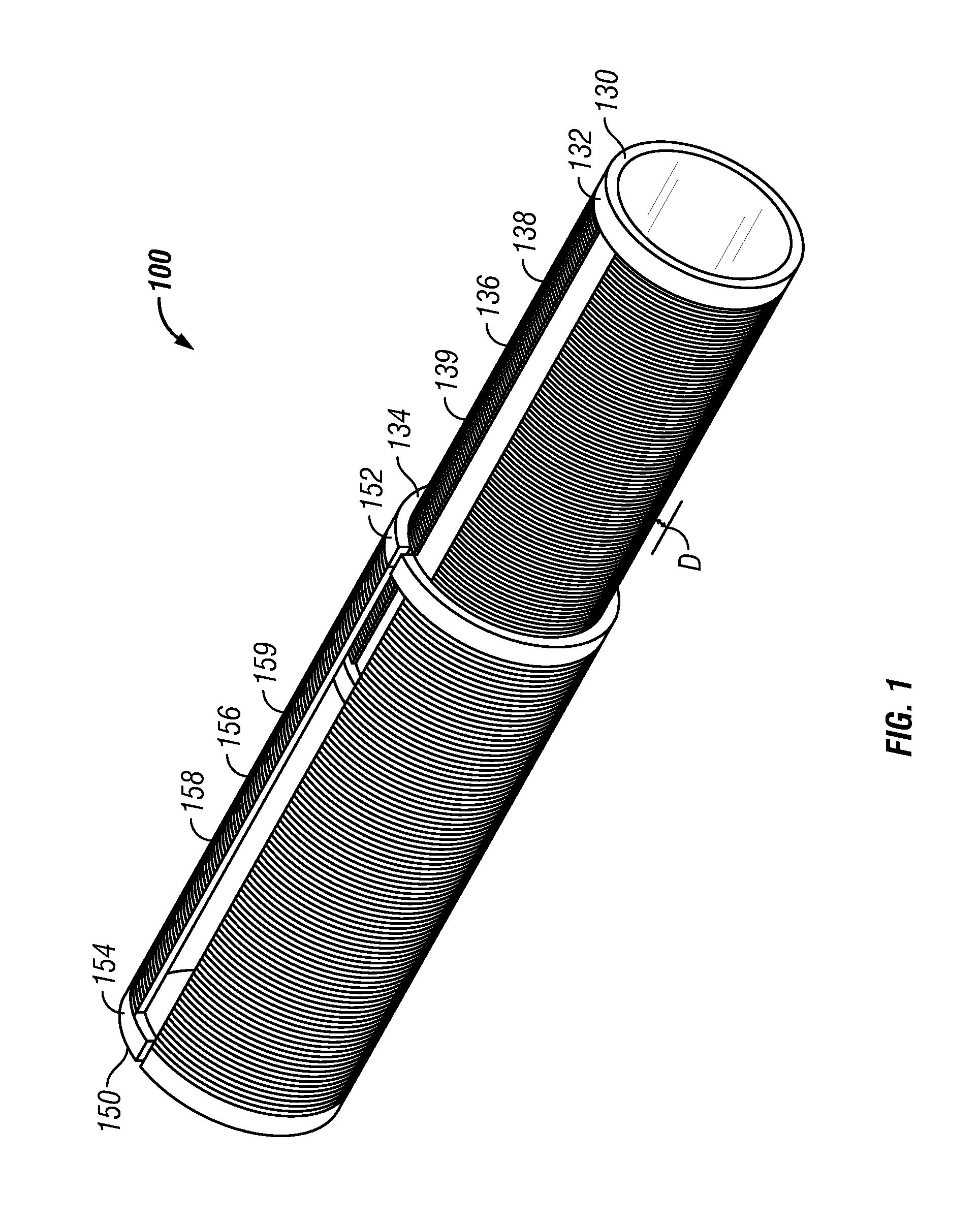
[0017] FIG. 1 illustrates one example of the one or more coils 120 of a coil assembly 100, which shows a multi-layered assembly. In this initial discussion, an example of two layers are shown, however, additional layers can be used as well. For instance, in an option, 2-4 layers of wire can be used. In another option 2-10 layers can be used. The layers can be spaced apart and placed in different orientations. This assists in reducing self capacitance of the antennas and allows for additional winding around the support members or mandrels.
[0018] In an option, a first support member 130 is provided and extends from a first end portion 132 to a second end portion 134. The support member(s) can be made from ceramic material, fiberglass, a ceramic coated with rubber, or a combination thereof The first support member 130 further includes a first single layer of wire 136 therearound, which in one option, operates as a transmitter coil 122 or a receiver coil 124. In an option, the first support member 130 includes one or more grooves 138 therein. The one or more grooves 138 in an option follow a helical path around the outer periphery of the first support member 130, and the wire 136 is received within the one or more grooves 138. The first support member 130 is generally cylindrical in shape, in an option, and is sized to be received within a second support member 150. In a further option, a coating 139 is disposed over the wire 136, which protects the wire after it is wound around the first support member 130 or disposed within grooves 138 of the first support member. In an option, the second support member 150 is provided and extends from a first end portion 152 to a second end portion 154. The second support member 150 further includes a second single layer of wire 156 therearound, which operates as a receiver coil 124 or a transmitter coil. In another option, the second single layer of wire 156 is electrically coupled with the first single layer of wire 136 to form a single antenna. For instance, the first coil and the second coil are electrically coupled and form a single antenna.
[0019] In an option, the second support member 150 includes one or more grooves 158 therein. The one or more grooves 158 in an option follow a helical path around the outer periphery of the second support member 150, and the wire 156 is received within the one or more grooves 158. The second support member 150 is generally cylindrical in shape, in an option, and is sized to receive the first support member 130 within an interior portion of the second support member 150. In a further option, a coating 159 is disposed over the wire 156.
[0020] The first support member 130 is disposed within the second support member 150. The second support member 150 has a thickness D which allows for the wire 156 of the receiver, or the transmitter, or another coil, to be spaced from the wire 136 of the transmitter by the distance D. In an option, the distance D is equal to or greater than 0.1 inches (2.54 mm). In another option, the distance D is about 0.125 inches (3.175 mm). In an option, the wire 136 is wound generally parallel with the wire 156. In another option, the wire 136 is would such that it is orthogonal with the wire 156. In a further option, the coil formed by the second layer of wire 156 and the coil formed by the first layer of wire 136 are concentric. The coil assembly 100 can be incorporated in the various downhole tools, including the tools discussed above, such as, but not limited to, a wireline tool or a drill string, or NMR tools. In another option, the coil assembly can be in a casing and placed permanently in a field.
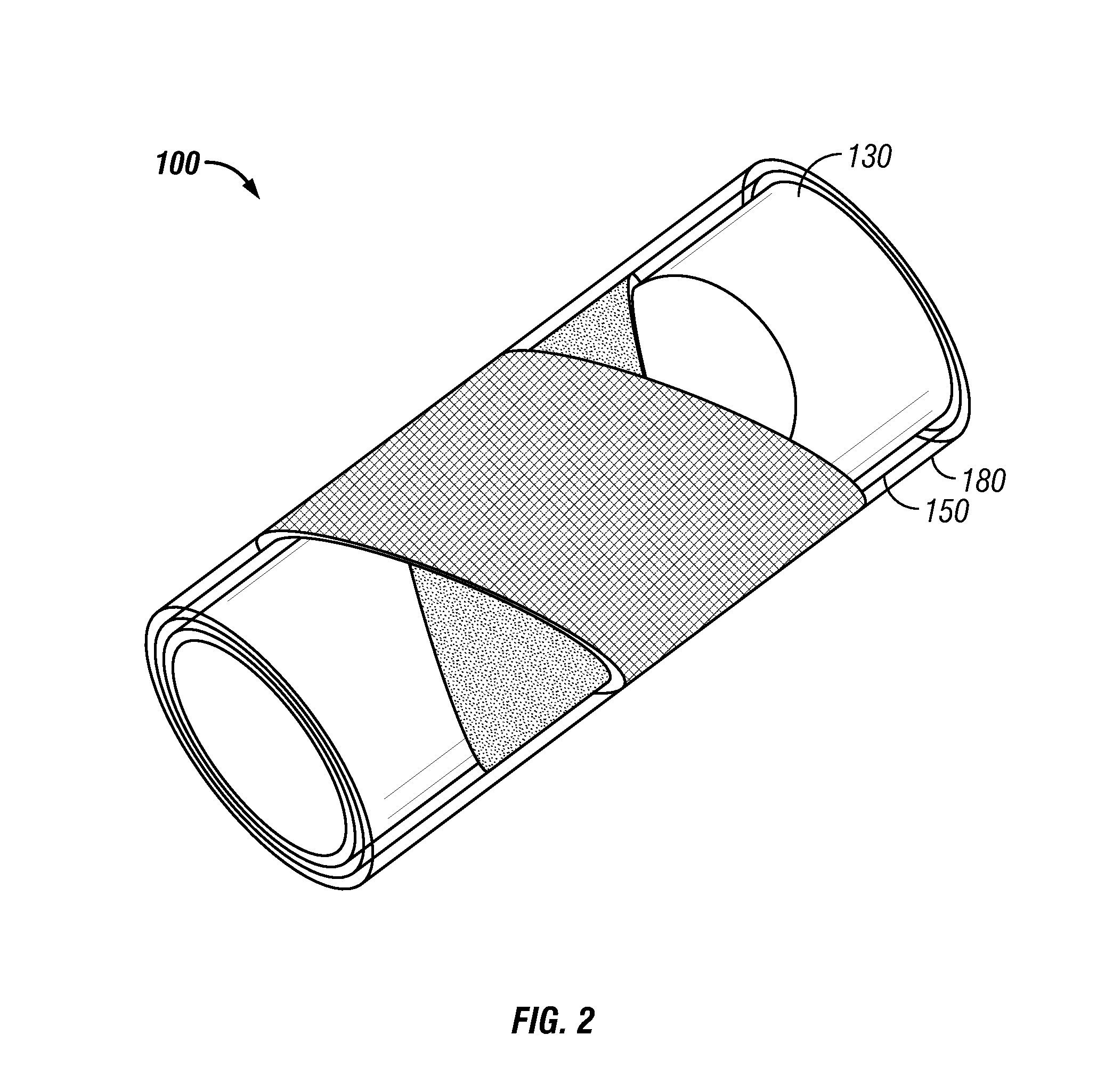
[0021] FIGS. 2 and 3 illustrate another embodiment, where FIG. 3 illustrates an exploded perspective view of FIG. 2. A coil assembly 100 includes a first support member 130 and a second support member 150 as discussed above. The first support member 130 further includes a first single layer of wire 136 therearound, which operates as a transmitter coil 122 or a receiver coil 124 (FIGS. 4A, 4B). In an option, the first support member 130 includes one or more grooves 138 therein. The one or more grooves 138 in an option follow a helical path around the outer periphery of the first support member 130, and the wire 136 is received within the one or more grooves 138. The first support member 130 is generally cylindrical in shape, in an option, and is sized to be received within a second support member 150. In a further option, a coating 139 is disposed over the wire 136, which protects the wire after it is wound around the first support member 130 or disposed within grooves 138 of the first support member.
[0022] The second support member 150 further includes a second single layer of wire 156 therearound, which operates as a transmitter coil 122 or a receiver coil 124 (FIGS. 4A, 4B). The second single layer of wire 156, in an option, is wrapped orthogonal around the second support member 150 such that it is orthogonal to the first wire 136. In an option, the second support member 150 includes one or more grooves 158 therein. The one or more grooves 158 in an option follow a helical path around the outer periphery of the second support member 150, and the wire 156 is received within the one or more grooves 158. The second support member 150 is generally cylindrical in shape, in an option, and is sized to receive the first support member 130 within an interior portion of the second support member 150. In a further option, a coating 159 is disposed over the wire 156.
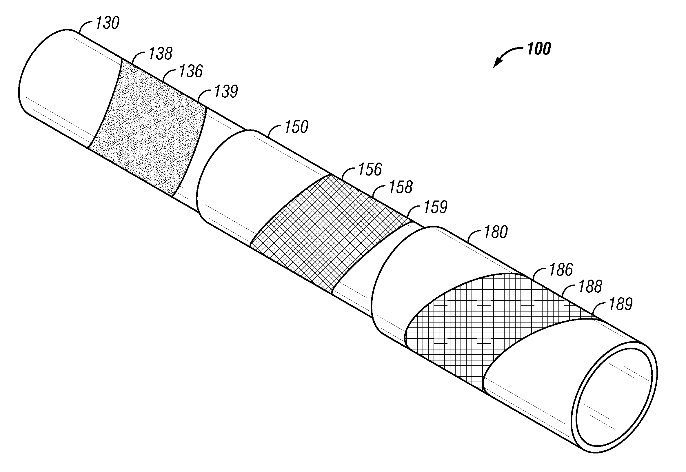
[0023] In a further option, a third support member 180 further includes a third single layer of wire 186 therearound, which operates as a second receiver coil 124. In an option, the wire 186 is wrapped around the third support member 180 such that it is orthogonal to the second layer of wire 156. In an option, the third support member 180 includes one or more grooves 188 therein. The one or more grooves 188 in an option follow a helical path around the outer periphery of the third support member 180, and the wire 186 is received within the one or more grooves 188. The third support member 180 is generally cylindrical in shape, in an option, and is sized to receive the second support member 150 within an interior portion of the third support member 180. In a further option, a coating 189 is disposed over the wire 186.
[0024] The first support member 130 is disposed within the second support member 150, and the second support member 150 is disposed within the third support member 180. The second support member 150 and the third support member 180 have a thickness D which allows for the wire 156 of the receiver coils, or transmitter coils, or another coil, to be spaced from the wire 136 by the distance D, and allows for the wire 186 to be spaced from the wire 156. In an option, the distance D is equal to or greater than 0.1 inches (2.54 mm). In an option, the wire 136 is wound generally orthogonal with the wire 156. In a further option, wire 186 is generally orthogonal with wire 156. The wire 136, 156, 186 can be electrically isolated from one another. The coil assembly can be incorporated in the various downhole tools, include the tools discussed above, such as, but not limited to, a wireline tool or a drill string.
[0025] FIG. 5 illustrates another option for the induction coil assembly. In an option, the second support member 150 includes a layer of wire 156 which only partially covers a surface of the support member 150 outer periphery. In an option, the layer of wire 156 is a single layer of wire and optionally is coiled as shown in FIG. 5. The first support member 130 includes a layer of wire 136, such as a single layer of wire, which in an option covers a portion of the surface of the support member 130 outer periphery. In an option, the wire 136 is disposed in a pattern similar to the layer of wire 156 as shown in FIG. 5, such as in a coiled configuration. In an option, the wire 136 is disposed below wire 156. In another option, the wire 136 is only partially below wire 156. In yet another option, the wire 136 is rotated relative to wire 156 such that wire 136 is not directly below wire 156. Wires 136, 156 may be communicatively coupled together, or may form separate members.
[0026] A system includes a downhole tool including at least one transmitter coil and at least one receiver coil, including the coil assemblies discussed herein. Both transmitter coils and receiver coils are wound around support members having an axis that is generally aligned with a longitudinal axis of the downhole tool. The at least one transmitter coil and the at least one receiver coil are longitudinally positioned along the axis of the downhole tool.
[0027] During operation, an oscillator supplies alternating current with a predetermined frequency to the transmitter coils, thereby inducing voltage in the receiver coils. The voltage induced in the receiver coils results from the sum of all eddy currents induced in the surrounding formations by all transmitters. Phase sensitive electronics measure the receiver voltage that is in-phase with the transmitter current divided by magnitude of the transmitter current. When normalized with the proper scale factor, this gives the apparent conductivity of the formation.
[0028] In a further option, a method includes forming a coil assembly, such as a transmitter coil or a receiver coil, including wrapping a first support member with a first wire and forming a single layer of wire around the first support member, and wrapping a second support member with a second wire and forming a single layer of wire around the second support member. Optionally, the second wire is wrapped orthogonally relative to the first wire. The method further includes disposing the first support member within the second support member and forming the coil assembly, and electrically coupling the wire with a processor. Optionally, a coating is disposed over the wire of the first support member and/or the second support member. In another option, a sleeve of material is disposed over the wire of the first support member and/or the second support member.
[0029] Several options for the method are as follows. For instance, in an option, wrapping the wire around the first support member includes wrapping the first wire within a groove of the first support member. In another option, wrapping the wire around the second support member includes wrapping the second wire within a groove of the second support member. In yet another option, the method further includes wrapping a third wire over a third support member, and optionally the third wire is orthogonal to the second wire.
[0030] The method can be implemented in various types of downhole tools. For instance, the method further includes disposing the coil assembly in a drill string.
[0031] Alternatively, the method further includes disposing the coil assembly in a wireline tool.
[0032] In the description, numerous specific details such as logic implementations, opcodes, means to specify operands, resource partitioning/sharing/duplication implementations, types and interrelationships of system components, and logic partitioning/integration choices are set forth in order to provide a more thorough understanding of the present invention. It will be appreciated, however, by one skilled in the art that embodiments of the invention may be practiced without such specific details. In other instances, control structures, gate level circuits and full software instruction sequences have not been shown in detail in order not to obscure the embodiments of the invention. Those of ordinary skill in the art, with the included descriptions will be able to implement appropriate functionality without undue experimentation.
[0033] References in the specification to "one embodiment", "an embodiment", "an example embodiment", etc., indicate that the embodiment described may include a particular feature, structure, or characteristic, but every embodiment may not necessarily include the particular feature, structure, or characteristic. Moreover, such phrases are not necessarily referring to the same embodiment. Further, when a particular feature, structure, or characteristic is described in connection with an embodiment, it is submitted that it is within the knowledge of one skilled in the art to affect such feature, structure, or characteristic in connection with other embodiments whether or not explicitly described.
[0034] In view of the wide variety of permutations to the embodiments described herein, this detailed description is intended to be illustrative only; and should not be taken as limiting the scope of the invention. What is claimed as the invention, therefore, is all such modifications as may come within the scope of the following claims and equivalents thereto. Therefore, the specification and drawings are to be regarded in an illustrative rather than a restrictive sense.
* * * * *
D00000
D00001
D00002
D00003
D00004
D00005
D00006
XML
uspto.report is an independent third-party trademark research tool that is not affiliated, endorsed, or sponsored by the United States Patent and Trademark Office (USPTO) or any other governmental organization. The information provided by uspto.report is based on publicly available data at the time of writing and is intended for informational purposes only.
While we strive to provide accurate and up-to-date information, we do not guarantee the accuracy, completeness, reliability, or suitability of the information displayed on this site. The use of this site is at your own risk. Any reliance you place on such information is therefore strictly at your own risk.
All official trademark data, including owner information, should be verified by visiting the official USPTO website at www.uspto.gov. This site is not intended to replace professional legal advice and should not be used as a substitute for consulting with a legal professional who is knowledgeable about trademark law.