Led Control System
CHEN; CHUN-SHENG ; et al.
U.S. patent application number 13/197789 was filed with the patent office on 2012-12-27 for led control system. This patent application is currently assigned to HON HAI PRECISION INDUSTRY CO., LTD.. Invention is credited to CHUN-SHENG CHEN, FENG-LONG HE.
| Application Number | 20120326626 13/197789 |
| Document ID | / |
| Family ID | 47361223 |
| Filed Date | 2012-12-27 |


| United States Patent Application | 20120326626 |
| Kind Code | A1 |
| CHEN; CHUN-SHENG ; et al. | December 27, 2012 |
LED CONTROL SYSTEM
Abstract
An LED control system includes a platform controller unit, a peripheral interface control chip connecting with the platform controller unit, and an LED unit connecting with the peripheral interface control chip. The platform controller unit outputs control instructions to the peripheral interface control chip. The control instructions outputted by the platform controller unit is transformed via programming the peripheral interface control chip, so that the on/off state of the LED unit as well as brightness and color of light emitted from the LED unit can be controlled by pulse signals output from the output ports of the peripheral interface control chip.
| Inventors: | CHEN; CHUN-SHENG; (Tu-Cheng, TW) ; HE; FENG-LONG; (Shenzhen City, CN) |
| Assignee: | HON HAI PRECISION INDUSTRY CO.,
LTD. Tu-Cheng TW HONG FU JIN PRECISION INDUSTRY (Shenzhen) CO., LTD. Shenzhen City CN |
| Family ID: | 47361223 |
| Appl. No.: | 13/197789 |
| Filed: | August 4, 2011 |
| Current U.S. Class: | 315/294 ; 315/291 |
| Current CPC Class: | H05B 45/20 20200101; Y02B 20/30 20130101; Y02B 20/346 20130101; H05B 45/37 20200101 |
| Class at Publication: | 315/294 ; 315/291 |
| International Class: | H05B 37/02 20060101 H05B037/02 |
Foreign Application Data
| Date | Code | Application Number |
|---|---|---|
| Jun 24, 2011 | CN | 201110172828.1 |
Claims
1. An LED control system comprising: a platform controller unit; a peripheral interface control chip connecting with the platform controller unit, the platform controller unit outputting control instructions to the peripheral interface control chip; and an LED unit connecting with the peripheral interface control chip; wherein the control instructions outputted by the platform controller unit are transformed via programming the peripheral interface control chip, so that the on/off state of the LED unit as well as brightness and color of light emitted from the LED unit can be controlled by pulse signals output from the peripheral interface control chip.
2. The LED control system of claim 1, wherein the LED unit comprises three LEDs respectively emitting red, green and blue light, the red, green and blue light being mixed in the LED unit to form a light with predetermined brightness and color.
3. The LED control system of claim 2, wherein the peripheral interface control chip comprises three output ports, each of the LEDs of the LED unit connecting with one of the output ports of the peripheral interface control chip, the output ports of the peripheral interface control chip outputting pulse signals with different duty cycles to control the on/off states of the LEDs of the LED unit as well as brightness and colors of light emitted from the LEDs of the LED unit.
4. The LED control system of claim 3, further comprising a current voltage source, each of the LEDs comprising an anode and a cathode, the anode of each LED connecting with the current voltage source, the cathode of each LED connecting with one of the output ports of the peripheral interface control chip.
5. The LED control system of claim 3, wherein the peripheral interface control chip comprises four input ports, the platform controller unit comprises four output ports connecting with the four input ports of the peripheral interface control chip for outputting the control instructions to the peripheral interface control chip.
Description
BACKGROUND
[0001] 1. Technical Field
[0002] The present disclosure relates to light emitting diode (LED) control systems, and particularly to an LED control system with high working efficiency.
[0003] 2. Description of Related Art
[0004] Referring to FIG. 2, a conventional LED control system includes a platform controller hub (PCH), a microcontroller (MCU) connecting with the PCH, an LED driver connecting with the MCU, and an RGB LED connecting with the LED driver. The RGB LED includes three encapsulated LEDs respectively emitting red, green and blue light. The light with different colors emitted from the LEDs mixes to form a light with a desired color. The PCH outputs control signals to the MCU and then to the LED driver, so that brightness and color of the light emitted from the RGB LED can be controlled. However, before the control signals outputted by the PCH reach the RGB LED, the control signals must be transformed and transferred by the MCU and the LED driver in sequence. As a result, the working efficiency of the conventional LED control system is very low.
[0005] What is needed, therefore, is an LED control system which can overcome the limitations described.
BRIEF DESCRIPTION OF THE DRAWINGS
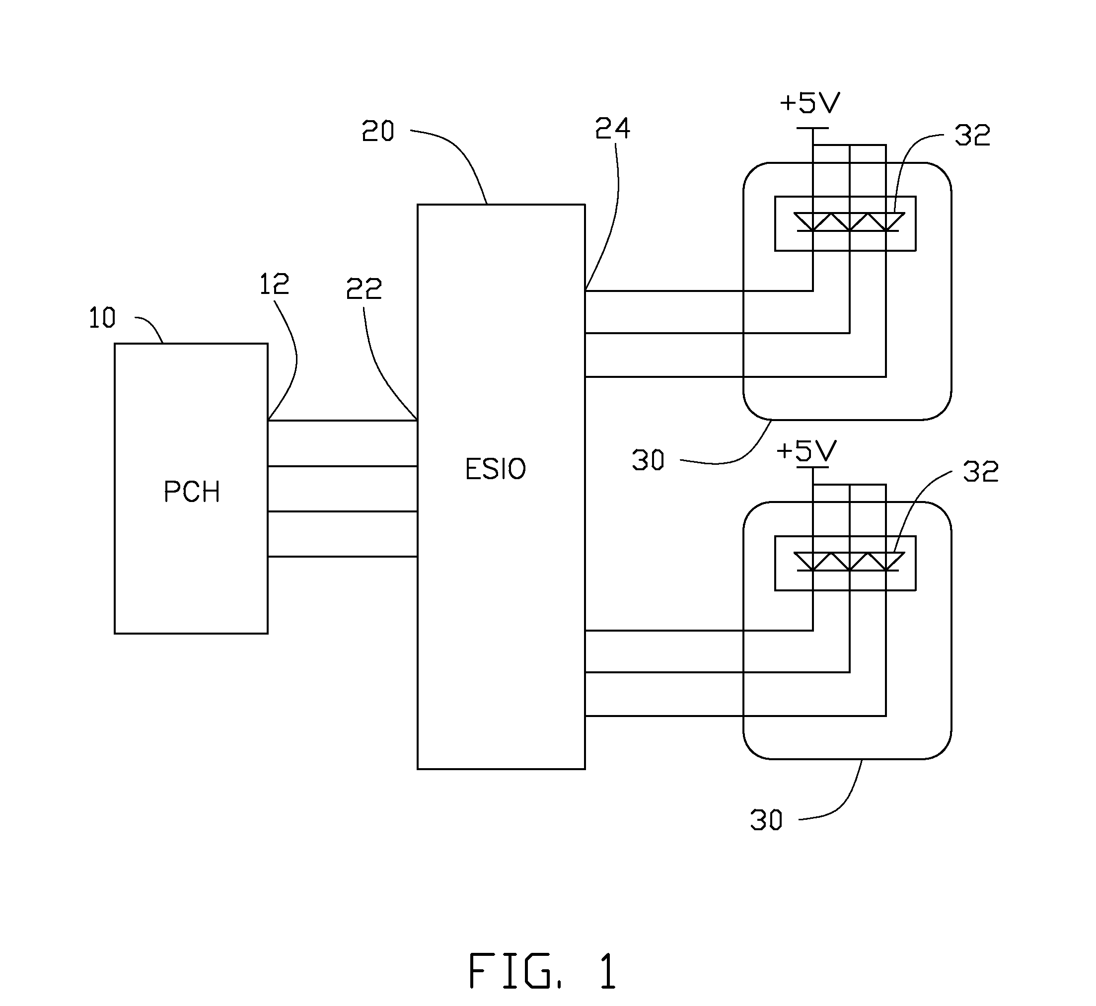
[0006] FIG. 1 is a schematic view of a circuit of an LED control system according to an exemplary embodiment of the present invention.
[0007] FIG. 2 is a schematic view of a circuit of a conventional LED control system.
DETAILED DESCRIPTION
[0008] Referring to FIG. 1, an LED control system according to an exemplary embodiment of the disclosure can be used in LED lamps. The LED control system includes a platform controller unit 10, a peripheral interface control chip 20, and two LED units 30.
[0009] The platform controller unit 10 uses a chip of Platform Controller Hub (PCH) produced by Intel Corporation. The platform controller unit 10 connects with the peripheral interface control chip 20 and outputs control instructions to the peripheral interface control chip 20. The platform controller unit 10 includes four output ports 12.
[0010] Each LED unit 30 includes three LEDs 32 encapsulated therein. The three LEDs 32 respectively emit red, green and blue light. The light with different brightness and colors emitted from the LEDs 32 can be mixed in the LED unit 30 to form a light with predetermined brightness and color. The anode of each LED 32 connects a current voltage source with 5 volts for providing electric energy for the LED unit 30.
[0011] The peripheral interface control chip 20 uses a chip of ESIO IT8731 produced by ITE Corporation. The peripheral interface control chip 20 includes four input ports 22 and six output ports 24. The four input ports 22 of the peripheral interface control chip 20 connect with the four output ports 12 of the platform controller unit 10. The cathode of each LED 32 connects with one of the output ports 24 of the peripheral interface control chip 20. The control instructions outputted by the platform controller unit 10 are transformed via programming the peripheral interface control chip 20, so that the on/off states of the LEDs 32 of the LED units 30 as well as brightness and colors of light emitted from the LEDs 32 of the LED units 30 can be controlled by pulse signals with different duty cycles output from the output ports 24 of the peripheral interface control chip 20.
[0012] According to the disclosure, the LED control system of the present invention uses the peripheral interface control chip 20 to replace the microcontroller and the LED driver of the conventional LED control system, so the LED control system of the present invention has a higher working efficiency and a lower cost in comparison with the conventional LED control system.
[0013] It is to be understood, however, that even though numerous characteristics and advantages of the disclosure have been set forth in the foregoing description, together with details of the structure and function of the embodiments, the disclosure is illustrative only, and changes may be made in detail, especially in matters of shape, size, and arrangement of parts within the principles of the invention to the full extent indicated by the broad general meaning of the terms in which the appended claims are expressed.
* * * * *
D00000
D00001
D00002
XML
uspto.report is an independent third-party trademark research tool that is not affiliated, endorsed, or sponsored by the United States Patent and Trademark Office (USPTO) or any other governmental organization. The information provided by uspto.report is based on publicly available data at the time of writing and is intended for informational purposes only.
While we strive to provide accurate and up-to-date information, we do not guarantee the accuracy, completeness, reliability, or suitability of the information displayed on this site. The use of this site is at your own risk. Any reliance you place on such information is therefore strictly at your own risk.
All official trademark data, including owner information, should be verified by visiting the official USPTO website at www.uspto.gov. This site is not intended to replace professional legal advice and should not be used as a substitute for consulting with a legal professional who is knowledgeable about trademark law.