Children's Walker
Corso; Daniel ; et al.
U.S. patent application number 13/532202 was filed with the patent office on 2012-12-27 for children's walker. This patent application is currently assigned to Kids II, Inc.. Invention is credited to Daniel Corso, Alexander Pusch.
| Application Number | 20120326409 13/532202 |
| Document ID | / |
| Family ID | 47361138 |
| Filed Date | 2012-12-27 |


| United States Patent Application | 20120326409 |
| Kind Code | A1 |
| Corso; Daniel ; et al. | December 27, 2012 |
CHILDREN'S WALKER
Abstract
Various embodiments of the present invention are directed to an adjustable orbital children's walker. According to various embodiments, the children's walker is configured for being adjusted between an orbital movement mode, in which the walker is restricted to movement along an orbital path, and a free movement mode, in which the walker is not restricted to movement along an orbital path. In particular, various embodiments of the children's walker include at least one pivot mechanism configured for being easily adjusted by a user between a first configuration, in which the children's walker is thereby in the orbital movement mode, and a second configuration, in which the children's walker is thereby in the free movement mode.
| Inventors: | Corso; Daniel; (Atlanta, GA) ; Pusch; Alexander; (Atlanta, GA) |
| Assignee: | Kids II, Inc. Atlanta GA |
| Family ID: | 47361138 |
| Appl. No.: | 13/532202 |
| Filed: | June 25, 2012 |
Related U.S. Patent Documents
| Application Number | Filing Date | Patent Number | ||
|---|---|---|---|---|
| 61500199 | Jun 23, 2011 | |||
| 61531831 | Sep 7, 2011 | |||
| Current U.S. Class: | 280/87.051 |
| Current CPC Class: | A47D 13/043 20130101 |
| Class at Publication: | 280/87.051 |
| International Class: | A47D 13/04 20060101 A47D013/04 |
Claims
1. A children's walker apparatus configured for movement along a support surface, the children's walker apparatus comprising: a child support configured for supporting a child; and a frame configured for suspending the child support above the support surface, the frame including: one or more movement members configured for engaging the support surface and permitting the frame to be moved along the support surface; and at least one pivot mechanism configured for being adjusted between a first configuration and a second configuration, wherein: when the pivot mechanism is in the first configuration, the children's walker is restricted to movement along an orbital path; and when the pivot mechanism is in the second configuration, the children's walker is free to move along a non-orbital path.
2. The children's walker apparatus of claim 1, wherein the at least one pivot mechanism is configured such that, when the pivot mechanism is in the first configuration, the at least one pivot mechanism engages the support surface and restricts the children's walker to orbital movement about the pivot mechanism.
3. The children's walker apparatus of claim 2, wherein the pivot mechanism includes a rotatable base member configured such that, when the pivot mechanism is in first configuration, the base member engages the support surface and permits the frame to rotate relative to the base member.
4. The children's walker apparatus of claim 2, wherein the at least one pivot mechanism is configured such that, when the pivot mechanism is in the second configuration, the pivot mechanism engages the support surface and permits the frame to be moved along the support surface.
5. The children's walker apparatus of claim 4, wherein the at least one pivot mechanism comprises a base member rotatably connected to the frame and a caster configured for rolling movement along the support surface; wherein, when the pivot mechanism is in the first configuration, the base member is positioned lower than the caster and is configured to engage the support surface and restrict the frame to orbital movement about the base member; and wherein, when the pivot mechanism is in the second configuration, the caster is positioned lower than the base member and is configured to engage the support surface and permit the frame to move along a non-orbital path.
6. The children's walker apparatus of claim 5, wherein the base member is operatively connected to the frame by a swivel bearing.
7. The children's walker apparatus of claim 5, wherein the caster comprises a ball caster.
8. The children's walker apparatus of claim 5, wherein the at least one pivot mechanism further comprises a housing defining a central cavity; wherein the base member is rotatably connected to a bottom surface of the housing, the base member defining a central aperture substantially aligned with the housing's central cavity; and wherein the caster is movably connected to the housing such that, when the pivot mechanism is in the first configuration, the caster is positioned within the central cavity such that it does not extend beneath the base member and, when the pivot mechanism is in the second configuration, the caster is extends at least partially out of the central cavity and beneath the base member.
9. The children's walker apparatus of claim 5, wherein the at least one pivot mechanism further comprises a housing defining a central cavity; wherein the base member is rotatably connected to a bottom surface of the housing, the base member defining a central aperture substantially aligned with the housing's central cavity; and wherein the base member is movably connected to the housing such that, when the pivot mechanism is in the first configuration, the base member is in a lower protracted positioned such that it extends beneath the caster and, when the pivot mechanism is in the second configuration, the base member is in an upper retracted position above the caster.
10. The children's walker apparatus of claim 4, wherein the at least one pivot mechanism comprises a caster configured to swivel relative to the frame; wherein, when the pivot mechanism is in the first configuration, the caster is locked such that it prevented from rolling along the support surface and thereby restricts the frame to orbital movement about the caster; and wherein, when the pivot mechanism is in the second configuration, the caster is free to rotate along the support surface and permit the frame to move along a non-orbital path.
11. The children's walker apparatus of claim 2, wherein the at least one pivot mechanism is configured such that, when the pivot mechanism is in the second configuration, the pivot mechanism does not engage the support surface.
12. The children's walker apparatus of claim 11, wherein the at least one pivot mechanism is rotatably connected to the frame and includes a base member rotatably connected to a lower surface of the pivot mechanism; wherein, when the pivot mechanism is in the first configuration, the pivot mechanism is rotated to a downward position in which the base member is configured to engage the support surface and restrict the frame to orbital movement about the base member; and wherein, when the pivot mechanism is in the second configuration, the pivot mechanism is rotated to an upward position in which the base member is configured not to engage the support surface and permit the frame to move along a non-orbital path.
13. The children's walker apparatus of claim 1, wherein the one or more movement members comprise one or more casters configured for rolling movement along the support surface.
14. The children's walker apparatus of claim 1, wherein the child support is configured to permit the legs of a child positioned therein to extend downwardly and push against the support surface in order to move the children's walker along the orbital and non-orbital paths, respectively.
15. The children's walker apparatus of claim 1, wherein, when the pivot mechanism is in the second configuration, the children's walker is configured for omnidirectional movement along the support surface.
16. The children's walker apparatus of claim 1, wherein the frame further comprises a lever configured to selectively adjust the at least one pivot mechanism between the first configuration and the second configuration.
Description
CROSS-REFERENCE TO RELATED APPLICATIONS
[0001] This application claims priority from provisional U.S. Application No. 61/500,199 entitled "Infant Walker Devices," which was filed on Jun. 23, 2011, and from provisional U.S. Application No. 61/531,831 entitled "Infant Walker," which was filed Sep. 7, 2011, each of which is herein incorporated by reference.
BACKGROUND OF THE INVENTION
[0002] 1. Field of the Invention
[0003] Various embodiments of the present invention described herein generally relate to children's walker apparatuses, particularly children's walker apparatuses adapted for orbital motion.
[0004] 2. Description of Related Art
[0005] Conventional children's walkers typically include a child seat suspended by a frame configured to roll along a support surface. The child seat is positioned such that the legs of a child positioned therein hang downwardly from the seat, thereby enabling the child to push on the support surface and move the walker in various directions. However, these conventional walkers do not significantly restrict the movement of the child, which can be inconvenient when a caretaker needs the child to remain in a particular area.
[0006] In addition to these conventional walkers, orbital walkers, such as that disclosed in U.S. Pat. No. 7,507,162 to Jackson et al., are also known in the art. These orbital walkers typically include a seat portion that is connected to a stationary platform and configured to move along an orbital path around the center of the stationary platform. This type of walker allows the child to practice the skill of walking while preventing the child from moving outside of the orbital path. However, orbital walkers of this type are not able to permit the child to move in other, non-orbital directions where such freedom of motion may be desired by a caretaker.
[0007] Accordingly, there remains a need in the art for an improved children's walker that is able to provide greater flexibility in its restriction of a child's motion.
BRIEF SUMMARY OF THE INVENTION
[0008] Various embodiments of the present invention are directed to a children's walker apparatus configured for movement along a support surface. According to various embodiments, the children's walker apparatus comprises a child support configured for providing a seating surface for a child and a frame configured for suspending the child support above the support surface. In various embodiments, the frame includes one or more movement members configured for engaging the support surface and permitting the frame to be moved along the support surface, and at least one pivot mechanism configured for being adjusted between a first configuration and a second configuration. When the pivot mechanism is in the first configuration, the children's walker is restricted to movement along an orbital path. When the pivot mechanism is in the second configuration, the children's walker is free to move along a non-orbital path.
[0009] In certain embodiments, the at least one pivot mechanism is configured such that, when the pivot mechanism is in the first configuration, the at least one pivot mechanism engages the support surface and restricts the children's walker to orbital movement about the pivot mechanism. In further embodiments, the pivot mechanism includes a rotatable base member configured such that, when the pivot mechanism is in first configuration, the base member engages the support surface and permits the frame to rotate relative to the base member.
BRIEF DESCRIPTION OF THE SEVERAL VIEWS OF THE DRAWINGS
[0010] Reference will now be made to the accompanying drawings, which are not necessarily drawn to scale, and wherein:
[0011] FIG. 1 shows a perspective view of a children's walker apparatus according to one embodiment of the present invention;
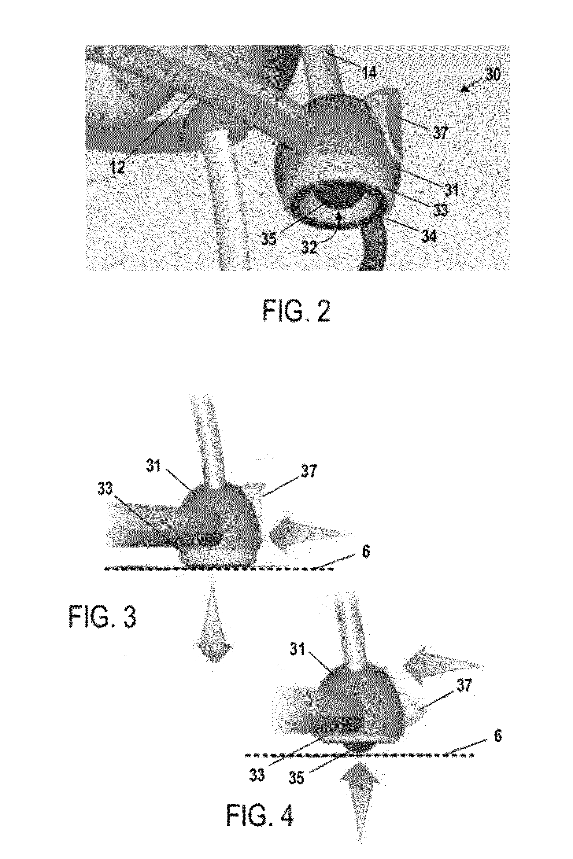
[0012] FIG. 2 shows a bottom perspective view of an adjustable caster assembly according to one embodiment of the present invention;
[0013] FIG. 3 shows a side view of an adjustable caster assembly in a first configuration according to one embodiment of the present invention;
[0014] FIG. 4 shows a side view of an adjustable caster assembly in a second configuration according to one embodiment of the present invention;
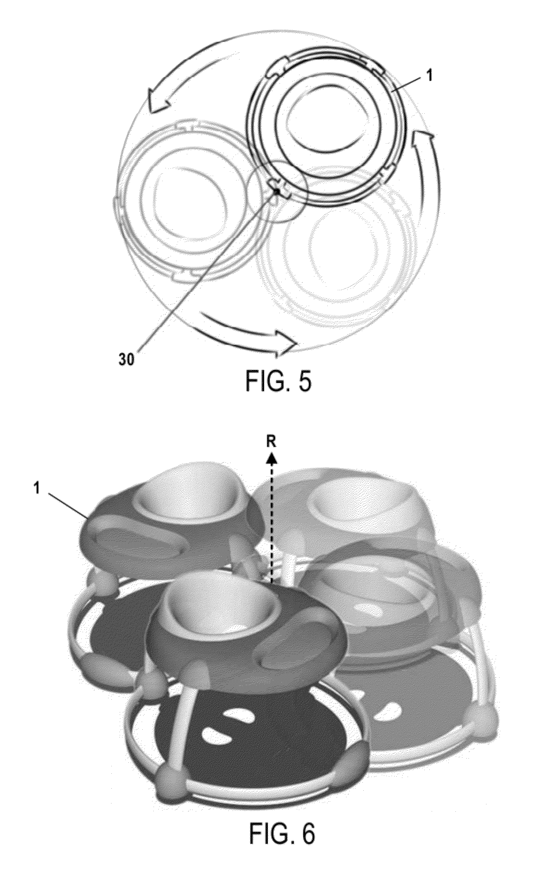
[0015] FIG. 5 shows a top view of the movement of a children's walker when the walker is configured in an orbital movement mode according to one embodiment of the present invention;
[0016] FIG. 6 shows a perspective view of the movement of a children's walker when the walker is configured in an orbital movement mode according to one embodiment of the present invention;
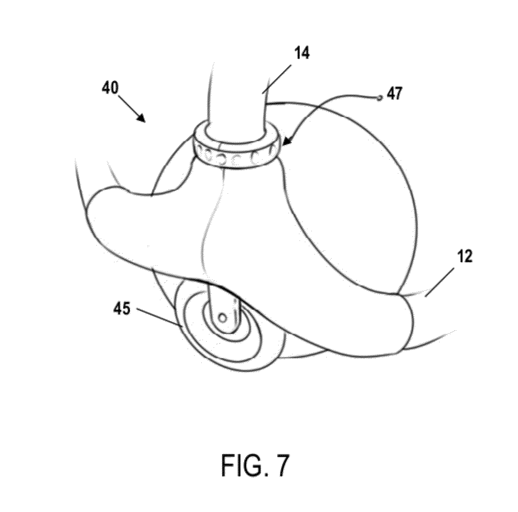
[0017] FIG. 7 shows a perspective view of an adjustable caster assembly according to another embodiment of the present invention;
[0018] FIG. 8 shows a perspective view of a children's walker apparatus according to another embodiment of the present invention; and
[0019] FIG. 9 shows a side view of an adjustable foot assembly according to one embodiment of the present invention.
DETAILED DESCRIPTION OF THE INVENTION
[0020] The present invention now will be described more fully hereinafter with reference to the accompanying drawings, in which embodiments of the invention are shown. This invention may, however, be embodied in many different forms and should not be construed as limited to the embodiments set forth herein; rather, these embodiments are provided so that this disclosure will be thorough and complete, and will fully convey the scope of the invention to those skilled in the art. Like numbers refer to like elements throughout.
[0021] Various embodiments of the present invention are directed to a children's walker apparatus configured to support a child as he or she walks along a support surface. According to various embodiments, the children's walker apparatus generally comprises a frame configured for suspending a child support (e.g., a rigid child seat or flexible sling) above the support surface (e.g., a floor). The frame includes one or more movement members configured for engaging the support surface and permitting the frame to be moved along the support surface. As an example, in one embodiment, the movement members may comprise one or more casters disposed on a lower surface of the frame and configured to permit the frame to be rolled along the support surface.
[0022] According to various embodiments, the children's walker is configured for being adjusted between an orbital movement mode and a free movement mode. In particular, various embodiments of the children's walker include at least one pivot mechanism configured for being adjusted between a first configuration, in which the children's walker is thereby in the orbital movement mode, and a second configuration, in which the children's walker is thereby in the free movement mode. As described in greater detail herein, various embodiments of the pivot mechanism are configured to selectively engage the support surface on which the children's walker is positioned in order to restrict the movement of the children's walker. For example, according to various embodiments, in the first configuration, the pivot mechanism is generally configured to restrict the children's walker to movement along an orbital path. In the second configuration, the pivot mechanism permits the walker to move along a non-orbital path (e.g., other directional or omnidirectional movement as permitted by the frame's movement members). As used herein, the term "pivot mechanism" is intended to refer to one or more features of the children's walker configured for restricting the children's walker to movement along an orbital path and is not intended to be limited to mechanisms that include a pivoting component or that function strictly mechanically.
[0023] According to various embodiments, the pivot mechanism is configured to be easily adjusted by a user between the first and second configurations in order to permit the children's walker to be changed between the orbital movement mode and the free movement mode. As described in greater detail below, the children's walker may include a lever or twisting member configured to adjust the pivot mechanism between the first and second configurations. In this way, a user can easily adjust the children's walker into the orbital movement mode in order to fix the direction and distance a child positioned in the children's walker can move. Likewise, when the user would like to permit the child to move in other directions and areas, the children's walker can easily be adjusted to the free movement mode.
Adjustable Orbital Walker
[0024] FIG. 1 illustrates an adjustable orbital children's walker 1 according to one embodiment of the present invention. As shown in FIG. 1, the children's walker 1 generally comprises a child support 5 suspended from a support frame 10. The frame 10 generally comprises a base portion 12, upwardly extending legs 14, and an upper portion 16. In the illustrated embodiment, the upper portion 16 comprises an activity table, which may include a food tray, various toys, accessories, and other entertainment features. In addition, in the illustrated embodiment of FIG. 1, the child support 5 comprises a fabric sling suspended from a rotatable member secured within the center of the frame's upper portion 16. However, according to various embodiments, the child support 5 may comprise any suitable seat or support device capable of suspending a child positioned in the children's walker 1 above a support surface (e.g., a rigid child seat disposed within the center of the frame's upper portion 16). In various embodiments, the child support 5 is configured to permit the legs of a child positioned therein to extend downwardly and push against the support surface in order to move the children's walker 1 along the support surface (e.g., along orbital or non-orbital paths as described in detail herein). In order to accommodate children of different ages or sizes, certain embodiments of the child support 5 may also be height adjustable (e.g., via a height adjustment mechanism that raises or lowers the position of the child support 5 with respect to the support surface).
[0025] According to various embodiments, the frame 10 also includes a plurality of movement members configured for engaging the support surface and permitting the frame 10 to be moved along the support surface (e.g., by rolling or sliding movement). In the illustrated embodiment of FIG. 1, the movement members comprise three non-adjustable casters 20 and one adjustable caster assembly 30. In certain embodiments, the non-adjustable casters 20 are generally configured for omnidirectional rolling movement along a support surface. For example, in one embodiment, the non-adjustable casters 20 are ball casters configured to swivel with respect to the frame 10. In addition, as shown in FIG. 1, each of the non-adjustable casters 20 is partially surrounded by a housing in order limit or prevent a child or caregiver from contacting the casters 20 as the children's walker is moved along the support surface. According to various other embodiments, other movement members may be provided in place of, or in addition to, the non-adjustable casters 20 (e.g., other rolling components and/or sliding components such as low-friction skis). Moreover, as will be appreciated from the description herein, the movement members may be separate components secured to the frame, or may be defined by a portion of the frame itself (e.g., portions of the frame configured to slide along the support surface).
[0026] FIG. 2 shows a detailed view of the adjustable caster assembly 30 according to one embodiment. In the illustrated embodiment, the adjustable caster assembly 30 is configured to serve as an pivot mechanism that can be adjusted between a first configuration, in which the children's walker is thereby in the orbital movement mode, and a second configuration, in which the children's walker is thereby in the free movement mode. As shown in FIG. 2, the adjustable caster assembly 30 generally comprises a housing 31 defining a central cavity 32. In the illustrated embodiment, the housing 31 is provided proximate the intersection of the frame's base portion 12 and one of the frame's legs 14. A base member 33 is rotatably connected to a lower surface of housing 31 such that it can rotate with respect to the housing 31. In particular, the base member 33 defines a central aperture that is substantially aligned with the central cavity 32. In one embodiment, the base member 33 is operatively connected to the housing 31 by a swivel bearing such that it functions in a manner akin to a "Lazy Susan" device. In addition, a non-slip surface 34 (e.g., a rubber gripping surface) is disposed on the lower surface of the base member 33 and is configured for engaging and gripping the support surface (e.g., a floor).
[0027] As shown in FIG. 2, a ball caster 35 is operatively connected to the housing 31 and disposed partially within the central cavity 32. In particular, in the illustrated embodiment, a lower portion of the ball caster 35 extends out of the central cavity 32 in order to permit the ball caster 35 to engage the support surface. In addition, according to various embodiments, the ball caster 35 may be configured to swivel relative to the housing 31.
[0028] In the illustrated embodiment of FIG. 2, the adjustable caster assembly 30 includes a lever 37 configured to selectively adjust the position of the base member 33 and ball caster 35 relative to one another. For example, in the illustrated embodiment of FIG. 2, the lever 37 is configured to raise and lower the base member 33. FIG. 3 shows the adjustable caster assembly 30 in a first configuration in which the base member 33 is in a lower position and extends beneath the bottom of the ball caster 35. As shown in FIG. 3, with the base member 33 in this lower position, the base member 33 engages the support surface 6 and the frame 10 can be rotated about the base member 33. In this configuration, the children's walker 1 is restricted to movement along an orbital path. In particular, as a child walks while positioned within the walker 1, the non-adjustable casters 20 will roll along the support surface 6 while the adjustable caster assembly 30 acts as a pivot point about which the children's walker 1 rotates. As a result, the children's walker 1 and the child positioned therein are limited to motion about the base member 33 along an orbital path.
[0029] FIGS. 5 and 6 depict examples of the orbital motion permitted by the adjustable caster assembly 30 when in the first configuration. In particular, FIG. 5 provides a top view of the children's walker 1 as it moves along an orbital path about the adjustable caster assembly 30, as indicated by the directional arrows. As noted above, the adjustable caster assembly 30 effectively defines a rotation axis about which the children's walker 1 may rotate when the adjustable caster assembly 30 is in the first configuration. FIG. 6 provides a perspective view of the children's walker 1 as it moves along an orbital path about a rotation axis R defined by the adjustable caster assembly 30.
[0030] FIG. 4 shows the adjustable caster assembly 30 in a second configuration in which the base member 33 is retracted upwardly to an upper position. As shown in FIG. 4, with the base member 33 in this upper position, ball caster 35 extends beneath the lower surface of the base member 33 and engages the support surface 6. In this configuration, the base member 33 does not engage the support surface 6 and the children's walker 1 is not restricted to movement along an orbital path. As such, the children's walker is free to move as permitted by the non-adjustable casters 20 and the ball caster 35. For example, in the illustrated embodiment, the non-adjustable casters 20 and the ball caster 35 are configured to swivel in relation to the frame 10 and the children's walker is thereby configured for omnidirectional movement when the adjustable caster assembly 30 is in the second configuration.
[0031] According various other embodiments, the lever 37 may be configured to raise and lower the ball caster 35 relative to the base member 33, thereby achieving the same effect as the embodiment shown in FIGS. 2-4. In addition, according to various embodiments, any number of non-adjustable casters 20 and adjustable caster assemblies 30 may be provided in order to suit various user preferences. For example, in certain embodiments, multiple adjustable caster assemblies 30 may be provided on the frame 10 such that a user may adjust any one of the adjustable caster assemblies 30 to the first configuration in order to place the children's walker 1 into the orbital movement mode.
Various Other Embodiments
[0032] As will be appreciated from the description herein, various changes and modifications to the children's walker 1 are contemplated as being within the scope of the present invention. For example, in certain embodiments, the walker's pivot mechanism may comprise an adjustable caster assembly 40 as shown in FIG. 7. In the illustrated embodiment of FIG. 7, the adjustable caster assembly 40 comprises a caster wheel 45 configured to be adjusted between a between a first configuration, in which the children's walker 1 is thereby in the orbital movement mode, and a second configuration, in which the children's walker 1 is thereby in the free movement mode. In particular, the adjustable caster assembly 40 includes a twist knob 47 configured to selectively lock the caster wheel 45 such that it is prevented from rotating, but remains able to swivel relative to the frame 10. Accordingly, a user may twist the knob 47 in order to lock the caster wheel 45 in a fixed position such that it may function as a pivot point about which the children's walker 1 may rotate. Thus, in this first locked configuration, the caster wheel 45 enables the walker 1 to function in an orbital movement mode. Likewise, a user may twist the knob 47 in an opposite direction in order to unlock the caster wheel 45 and permit it to rotate freely. Thus, in this second unlocked configuration, the caster wheel 45 enables the walker 1 to function in a free movement mode.
[0033] In certain embodiments, the casters 20 may also be configured for locking in a fixed orientation relative to the frame. For example, in one embodiment, each of the casters 20 may include a twist knob that, when tightened by a user, fixes its respective caster 20 in a non-swiveling orientation tangential to the adjacent section of the frame's base portion 12. In this way, each of the casters 20 may be fixed in a position that promotes orbital movement of the walker 1 about the adjustable caster assembly 40.
[0034] FIG. 8 illustrates another embodiment in which the walker's pivot mechanism comprises an adjustable foot assembly 50. As shown in FIG. 8, the adjustable foot assembly is operatively connected to the children's walker 1 proximate in the intersection of the frame's base portion 12 and one of the frame's legs 14. FIG. 9 provides a more detailed view of the adjustable foot assembly. In the illustrated embodiment of FIG. 9, the adjustable foot assembly 50 comprises a foot member 51 rotatably connected to the frame's leg 14 by a pin 52. As such, the foot member 51 is configured to selectively rotate about the pin 52.
[0035] As shown in FIG. 9, the adjustable foot assembly 50 also includes a base member 53 rotatably connected to a bottom surface of the foot member 51 (e.g., using a swivel bearing such that it may function as a Lazy Susan device). According to various embodiments, the foot member 51 is configured such it can rotated between a first configuration, in which the children's walker 1 is thereby in the orbital movement mode, and a second configuration, in which the children's walker 1 is thereby in the free movement mode. As shown in FIG. 9, in the first configuration, the foot member 51 is rotated to a lower position in which the base member 53 engages the support surface on which the walker 1 is positioned. As such, when the foot member 51 is in the first configuration, the walker 1 may rotate about the base member 53 such that the walker 1 is restricted to movement along an orbital path. In contrast, when the foot member 51 is rotated upward to the second configuration, the base member 53 does not engage the support surface and the children's walker 1 is not restricted to movement along an orbital path. As such, the children's walker 1 is free to move as permitted by the non-adjustable casters 20.
CONCLUSION
[0036] Many modifications and other embodiments of the inventions set forth herein will come to mind to one skilled in the art to which these inventions pertain having the benefit of the teachings presented in the foregoing descriptions and the associated drawings. Therefore, it is to be understood that the inventions are not to be limited to the specific embodiments disclosed and that modifications and other embodiments are intended to be included within the scope of the appended claims. Although specific terms are employed herein, they are used in a generic and descriptive sense only and not for purposes of limitation.
* * * * *
D00000
D00001
D00002
D00003
D00004
D00005
XML
uspto.report is an independent third-party trademark research tool that is not affiliated, endorsed, or sponsored by the United States Patent and Trademark Office (USPTO) or any other governmental organization. The information provided by uspto.report is based on publicly available data at the time of writing and is intended for informational purposes only.
While we strive to provide accurate and up-to-date information, we do not guarantee the accuracy, completeness, reliability, or suitability of the information displayed on this site. The use of this site is at your own risk. Any reliance you place on such information is therefore strictly at your own risk.
All official trademark data, including owner information, should be verified by visiting the official USPTO website at www.uspto.gov. This site is not intended to replace professional legal advice and should not be used as a substitute for consulting with a legal professional who is knowledgeable about trademark law.