Phosphor And Leds Containing Same
Zheng; Yi
U.S. patent application number 13/583504 was filed with the patent office on 2012-12-27 for phosphor and leds containing same. This patent application is currently assigned to OSRAM SYLVANIA, INC.. Invention is credited to Yi Zheng.
| Application Number | 20120326196 13/583504 |
| Document ID | / |
| Family ID | 44712833 |
| Filed Date | 2012-12-27 |


| United States Patent Application | 20120326196 |
| Kind Code | A1 |
| Zheng; Yi | December 27, 2012 |
PHOSPHOR AND LEDS CONTAINING SAME
Abstract
There is herein described a phosphor for use in LED applications and particularly in phosphor-conversion LEDs (pc-LEDs). The phosphor has a composition represented by (Y.sub.1-xCe.sub.x).sub.3(Al.sub.1-ySc.sub.y).sub.5O.sub.12 wherein 0<x<=0.04 and 0<y<=0.6 and can be as applied to an LED as a transparent sintered ceramic or used in a powder form. By adjusting the composition of the phosphor, the phosphor can be made to emit light in the green to yellow regions of the visible spectrum upon excitation by a blue-emitting In--GaN LED.
| Inventors: | Zheng; Yi; (Lynnfield, MA) |
| Assignee: | OSRAM SYLVANIA, INC. Danvers MA |
| Family ID: | 44712833 |
| Appl. No.: | 13/583504 |
| Filed: | March 30, 2011 |
| PCT Filed: | March 30, 2011 |
| PCT NO: | PCT/US11/30536 |
| 371 Date: | September 7, 2012 |
Related U.S. Patent Documents
| Application Number | Filing Date | Patent Number | ||
|---|---|---|---|---|
| 61319666 | Mar 31, 2010 | |||
| Current U.S. Class: | 257/98 ; 252/301.4R; 257/E33.061 |
| Current CPC Class: | C04B 35/44 20130101; C04B 2235/3229 20130101; C04B 2235/6582 20130101; C04B 2235/3224 20130101; C04B 2235/656 20130101; C04B 2235/764 20130101; C09K 11/7774 20130101; C04B 2235/9653 20130101; H01L 33/502 20130101; C04B 2235/6588 20130101; C04B 2235/3225 20130101; C04B 2235/9661 20130101 |
| Class at Publication: | 257/98 ; 252/301.4R; 257/E33.061 |
| International Class: | C09K 11/80 20060101 C09K011/80; H01L 33/50 20100101 H01L033/50 |
Claims
1. A phosphor having a composition represented by (Y.sub.1-xCe.sub.x).sub.3(Al.sub.1-ySc.sub.y).sub.5O.sub.12 wherein 0<x.ltoreq.0.04 and 0<y.ltoreq.0.6.
2. The phosphor of claim 1 wherein the phosphor when excited emits light having color coordinates Cx and Cy wherein C.sub.x is in a range from about 0.35 to about 0.44 and C.sub.y is in a range from about 0.55 to about 0.58.
3. A phosphor-conversion LED comprising: an LED that emits a blue light and a phosphor for converting at least a portion of the blue light into light of a different wavelength, the phosphor having a composition represented by (Y.sub.1-xCe.sub.x).sub.3(Al.sub.1-ySc.sub.y).sub.5O.sub.12 wherein 0<x.ltoreq.0.4 and 0<y.ltoreq.0.6.
4. The phosphor-conversion LED of claim 3 wherein the blue light has a wavelength from about 420 nm to about 490 nm.
5. The phosphor-conversion LED of claim 3 wherein the phosphor when excited by the blue light by emitted by the LED emits light having color coordinates Cx and Cy wherein C.sub.x is in a range from about 0.35 to about 0.44 and C.sub.y is in a range from about 0.55 to about 0.58.
6. The phosphor-conversion LED of claim 5 wherein the blue light has a wavelength from about 420 nm to about 490 nm.
Description
CROSS REFERENCE TO RELATED APPLICATIONS
[0001] This application claims the benefit of and priority to co-pending PCT application PCT/US11/30536 filed Mar. 30, 2011 and to U.S. Provisional Application No. 61/319,666, filed Mar. 31, 2010.
TECHNICAL FIELD OF THE INVENTION
[0002] This invention relates to light emitting diodes (LED) and more particularly to phosphors for use in LED applications such as phosphor-conversion LEDs.
BACKGROUND OF THE INVENTION
[0003] Current white-light-emitting phosphor-conversion LEDs (pc-LEDs) utilize one or more phosphors to partially absorb blue light emissions from InGaN LEDs in order to convert some of the blue light into a yellow light. The combination of the remaining unabsorbed blue light and converted yellow light yields light which is perceived as white. Other phosphors may be used in addition to the yellow-emitting phosphor, for example a red-emitting phosphor, in order to increase color rendering index (CRI) or achieve a different color temperature (CCT). However, the yellow-emitting phosphor remains the core component in white pc-LEDs.
[0004] The normal yellow-emitting phosphor used in a pc-LED is a cerium-activated yttrium aluminum garnet, Y.sub.3Al.sub.5O.sub.12:Ce, phosphor (YAG:Ce). However, other phosphors include a cerium-activated terbium aluminum garnet (TAG:Ce) phosphor as described in U.S. Pat. No. 6,669,866 and silicate-based phosphors such as those described in U.S. Pat. Nos. 6,943,380, 6,809,347, 7,267,787, and 7,045,826.
[0005] An example of a YAG:Ce phosphor and its application in an LED are described in U.S. Pat. No. 5,998,925. Some composition modifications of YAG phosphors are also described in this patent, such as using Ga to replace Al or Gd to replace Y in the garnet. Generally, Ga substitution of Al shifts the emission peak to shorter wavelength and Gd substitution of Y shifts emission peak to longer wavelength.
SUMMARY OF THE INVENTION
[0006] A new phosphor for light emitting diode (LED) applications has been developed with a composition represented by (Y.sub.1-xCe.sub.x).sub.3(Al.sub.1-ySc.sub.y).sub.5O.sub.12 wherein 0<x.ltoreq.0.04 and 0<y.ltoreq.0.6. The color of the light emitted by the phosphor can be changed by adjusting the composition. For example, in one aspect, the phosphor can be used as a yellow-emitting phosphor in white pc-LEDs. In another aspect, the composition of the phosphor may be adjusted such that it may used as a green-emitting phosphor to fully convert the blue emission from a blue-emitting LED to a green emission. This is important since direct green-emitting InGaN LEDs have a very low efficiency. A green-emitting, full conversion pc-LED that uses the higher efficiency blue-emitting InGaN LEDs has the potential to offer more efficient green LEDs.
[0007] In accordance with an aspect of the invention, there is provided a phosphor having a composition represented by (Y.sub.1-xCe.sub.x).sub.3(Al.sub.1-ySc.sub.y).sub.5O.sub.12 wherein 0<x.ltoreq.0.04 and 0<y.ltoreq.0.6.
[0008] In accordance with another aspect of the invention, there is provided a phosphor-conversion LED comprising: an LED that emits a blue light and a phosphor for converting at least a portion of the blue light into light of a different wavelength, the phosphor having a composition represented by (Y.sub.1-xCe.sub.x).sub.3(Al.sub.1-ySc.sub.y).sub.5O.sub.12 wherein 0<x.ltoreq.0.04 and 0<y.ltoreq.0.6.
BRIEF DESCRIPTION OF THE DRAWINGS
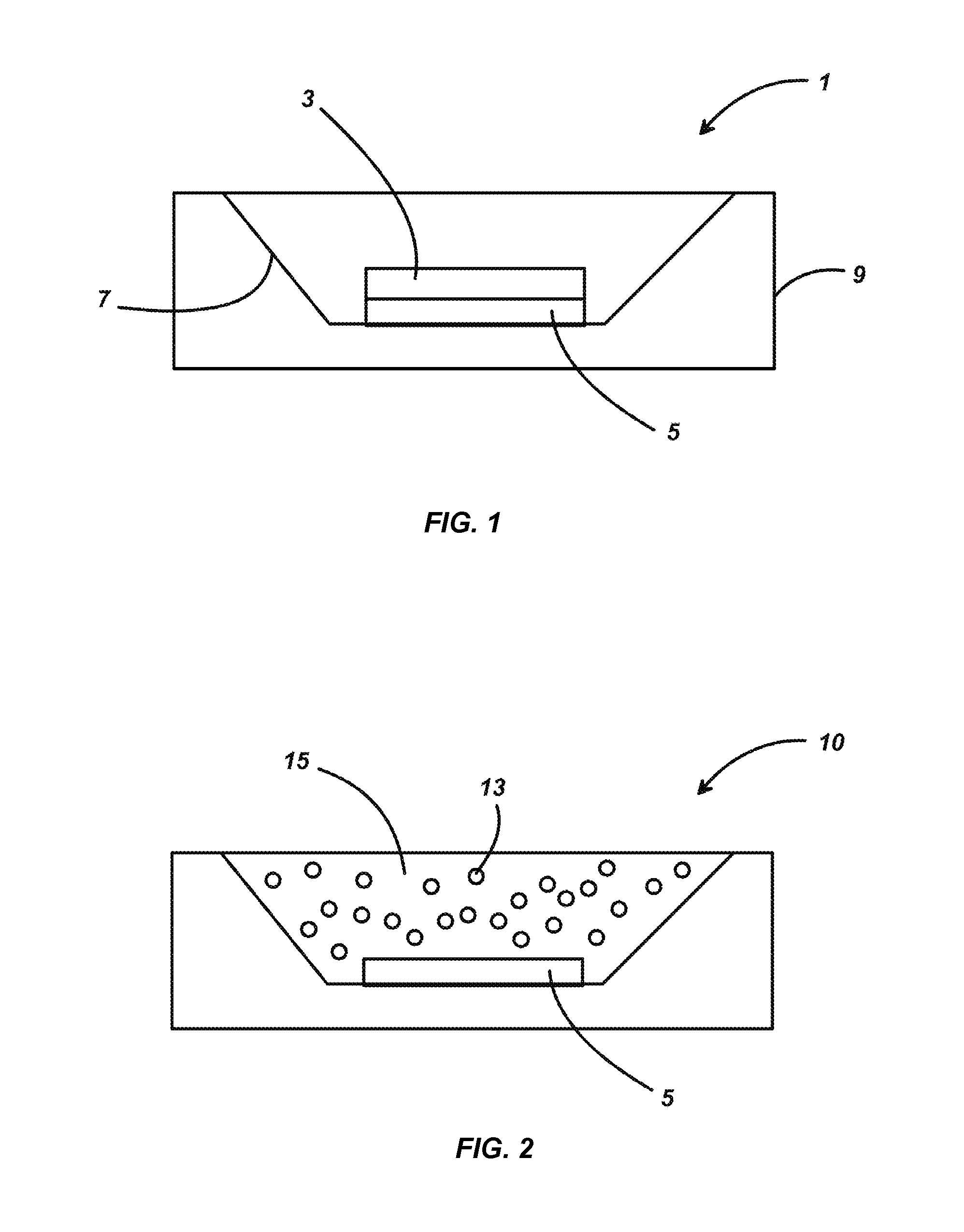
[0009] FIG. 1 is an illustration of an embodiment of a phosphor-conversion LED (pc-LED) according to this invention.
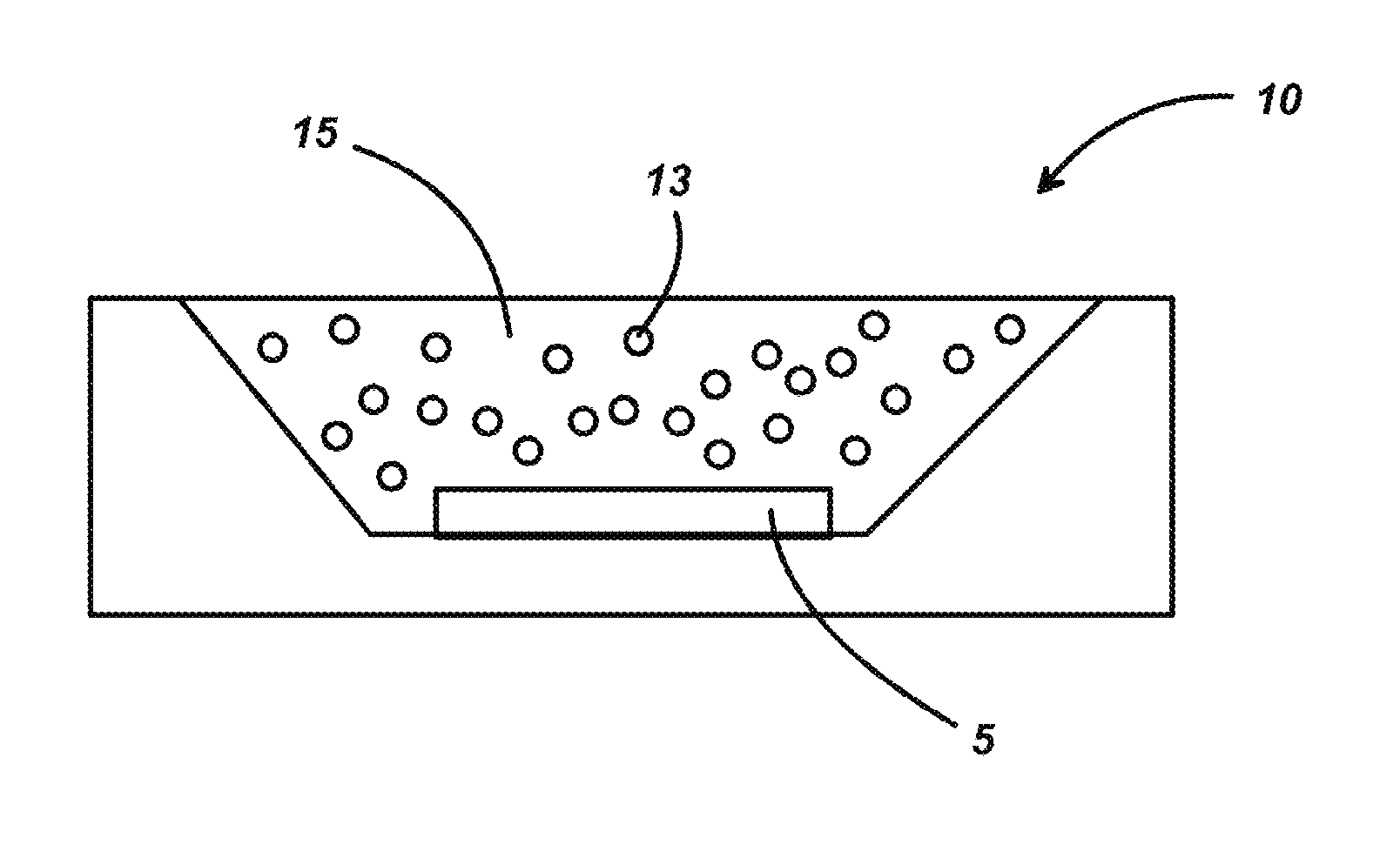
[0010] FIG. 2 is an illustration of an alternate embodiment of a pc-LED according to this invention.
[0011] FIG. 3 is an emission spectrum of a phosphor having a composition (Y.sub.0.995Ce.sub.0.005).sub.3(Al.sub.0.8Sc.sub.0.2).sub.5O.sub.12 in accordance with this invention (Example Y1).
[0012] FIGS. 4 and 5 are emission spectra of the phosphors of Examples Y1, and Y3-Y9.
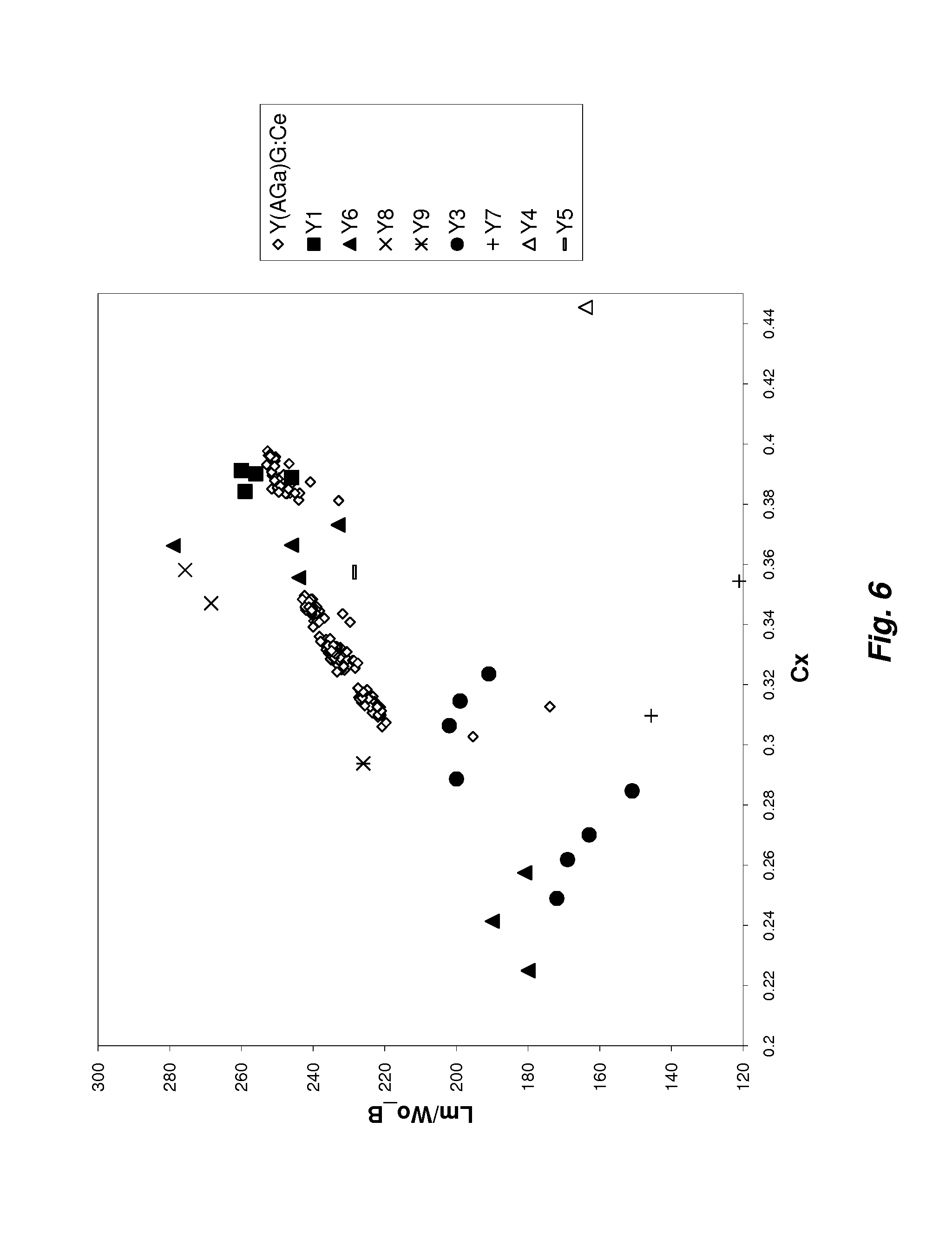
[0013] FIG. 6 is a graph of efficiency (lm/W.sub.o-B) vs. the C.sub.x color coordinate for various phosphor compositions according to this invention compared with conventional (Y.sub.1-xCe.sub.x).sub.3(Al.sub.1-yGa.sub.y).sub.5O.sub.12 phosphor.
DETAILED DESCRIPTION OF THE INVENTION
[0014] For a better understanding of the present invention, together with other and further objects, advantages and capabilities thereof, reference is made to the following disclosure and appended claims taken in conjunction with the above-described drawings.
[0015] FIG. 1 is an illustration of an embodiment of the phosphor-conversion LED 1 of this invention. The phosphor converter 3 in this case is a solid ceramic piece formed by pressing and sintering the powdered phosphor or its oxide precursors. The phosphor converter 3 is placed on top of the blue-emitting LED 5, which preferably emits light having a wavelength from about 420 nm to about 490 nm. The LED 5 is shown here mounted in a module 9 having a well 7 with reflective sides, but the invention is not limited to this particular arrangement.
[0016] FIG. 2 is an illustration of an alternate embodiment of the invention. In this case, the phosphor-conversion LED 10 is encapsulated in a resin 15 in which particles of phosphor 13 are dispersed.
EXAMPLES
[0017] Several phosphors of varying composition were made using commercially available oxide powders of Y.sub.2O.sub.3, Al.sub.2O.sub.3, Sc.sub.2O.sub.3 and CeO.sub.2 which were mixed in amounts to produce the desired composition (see Table 1). The mixed powders were then pressed into discs and sintered under varying conditions to form the phosphors. Although these samples were formed as sintered ceramic discs, the phosphor may also be formed as a powder.
TABLE-US-00001 TABLE 1 Batch Y.sub.2O.sub.3 Al.sub.2O.sub.3 sintering (gram) (gram) (gram) Sc.sub.2O.sub.3 (gram) CeO.sub.2 (gram) atmosphere Y1 2.7513 1.6447 0.5029 0.0211 wet H.sub.2 Y2 2.4623 0 2.5189 0.0189 wet H.sub.2 Y3 2.5988 0.786 1.5951 0.0199 wet H.sub.2 Y4 2.6592 1.4294 0.8286 0.0827 wet H.sub.2 Y5 2.7115 1.4356 0.8322 0.0208 wet H.sub.2 Y6 10.8864 5.7468 3.3306 0.0333 wet H.sub.2 Y7 11.2138 7.6108 1.1443 0.0347 wet H.sub.2 Y8 10.9668 6.203 2.7967 0.0343 wet H.sub.2 Y9 10.7322 4.8557 4.3781 0.0328 wet H.sub.2
Example Y1
[0018] Example Y1 was made with a nominal composition (Y.sub.0.995Ce.sub.0.005).sub.3(Al.sub.0.8Sc.sub.0.2).sub.5O.sub.12. The powder mix was dry pressed into discs under 300 MPa pressure. The pressed discs were sintered at 1800, 1850, 1880 and 1890.degree. C. under wet H.sub.2. The resulting sintered ceramic was a green-yellow color. The ceramic became more translucent as sintering temperature increased. The emission intensity also increased as temperature increased.
[0019] An example of Y1 emission under blue-light excitation is shown in the FIG. 3. The emission spectrum exhibits a broad yellow emission with a peak wavelength at 533 nm. The emission spectrum is very similar to YAG:Ce and indicates that the ceramic has a garnet structure.
Example Y2
[0020] Example Y2 was made with a nominal composition (Y.sub.0.995Ce.sub.0.005).sub.3SC.sub.5O.sub.12. The oxide powders were mixed and dry pressed into discs. The discs were sintered at 1850.degree. C. and 1900.degree. C. The resulting sintered ceramic was orange-red in color. However, no emission was observed under the blue excitation.
Example Y3
[0021] Example Y3 was made with a nominal composition (Y.sub.0.995Ce.sub.0.005).sub.3(Al.sub.0.4Sc.sub.0.6).sub.5O.sub.12. Discs were made by dry pressing the oxide powder mixture and then sintering at 1850.degree. C. and 1900.degree. C. Melting occurred when the sintering was done at 1900.degree. C. yielding a near white body color whereas the disc sintered at 1850.degree. C. had a green-yellow color. The emission of Y3 had a peak wavelength at 527 nm which is shifted to a shorter wavelength compared to example Y1.
Examples Y4 and Y5
[0022] Examples Y4 and Y5 were made with nominal compositions (Y.sub.0.98Ce.sub.0.02).sub.3(Al.sub.0.7Sc.sub.0.3).sub.5O.sub.12 and (Y.sub.0.995Ce.sub.0.005).sub.3(Al.sub.0.7Sc.sub.0.3).sub.5O.sub.12 respectively. Discs were made again by dry pressing mixed oxide powders and sintering at 1850.degree. C., 1860.degree. C. and 1880.degree. C. The resulting sintered ceramics were translucent with Y4 having a yellow color and Y5 a green-yellow color.
Example Y6
[0023] Example Y6 was made with a nominal composition (Y.sub.0.998Ce.sub.0.002).sub.3(Al.sub.0.7Sc.sub.0.3).sub.5O.sub.12. Oxide powders were mixed with DI water, polymer binders, and ball milled for an extended time. The ball-milled slurry was then dried and ground into a powder. Discs were made by isopressing under 30 k Psi. Using ball milling allows for the oxides to be mixed more homogenously and reduces agglomerates. The isopressed discs were sintered at 1850, 1860 and 1880.degree. C. under wet H.sub.2. Near fully transparent samples were obtained.
Example Y7
[0024] Example Y7 was made with a nominal composition (Y.sub.0.998Ce.sub.0.002).sub.3(Al.sub.0.9Sc.sub.0.1).sub.5O.sub.12. The oxide powders were mixed by ball milling as with Example Y6. The pressed discs were sintered at 1850 and 1880.degree. C. The resulting sintered discs were opaque.
Examples Y8 and Y9
[0025] Examples Y8 and Y9 were made to have nominal compositions (Y.sub.0.998Ce.sub.0.002).sub.3(Al.sub.0.75Sc.sub.0.25).sub.5O.sub.12 and (Y.sub.0.998Ce.sub.0.002).sub.3(Al.sub.0.6Sc.sub.0.4).sub.5O.sub.12 respectively. The oxide powders were mixed by ball milling as in Example Y6. The isopressed discs were sintered at 1860 and 1880.degree. C. Both compositions were found to capable of being sintered to near transparency.
[0026] Table 2 lists the CIE 1931 color coordinates (Cx,Cy), dominate wavelength (Ldom), peak wavelength (Lpeak), centroid wavelength (Lcentroid) and full width at half maximum (FWHM) of the blue-light-excited emissions for the above examples, except for Y2 which did not exhibit an emission. The C.sub.x color coordinates ranged from about 0.35 to about 0.44 and the C.sub.y color coordinates ranged from about 0.55 to about 0.58.
[0027] For the first group, examples Y7, Y1, Y8, Y6, Y9 and Y3, the emission peak shifts towards the green region of the visible spectrum (shorter wavelengths) as the percentage of Sc concentration increases. This behavior is very similar to increasing the level of Ga substitution for Al in (Y.sub.1-xCe.sub.x).sub.3(Al.sub.1-yGa.sub.y).sub.5O.sub.12 suggesting that Sc may have a similar structural role as Ga in the ceramics.
TABLE-US-00002 TABLE 2 Cx Cy Ldom/nm Lpeak/nm Lcentroid/nm FWHM/nm Y7 (Y.sub.0.998Ce.sub.0.002).sub.3(Al.sub.0.9Sc.sub.0.1).sub.5O.sub.12 0.4168 0.5599 567.0 551 572.5 113.0 Y1 (Y.sub.0.995Ce.sub.0.005).sub.3(Al.sub.0.8Sc.sub.0.2).sub.5O.sub.12 0.3983 0.5671 564.5 533 567.5 108.3 Y8 (Y.sub.0.998Ce.sub.0.002).sub.3(Al.sub.0.75Sc.sub.0.25).sub.5O.sub.12 0.3792 0.5673 562.0 530 562.5 108.2 Y6 (Y.sub.0.998Ce.sub.0.002).sub.3(Al.sub.0.7Sc.sub.0.3).sub.5O.sub.12 0.3762 0.5673 561.6 528 561.6 108.9 Y9 (Y.sub.0.998Ce.sub.0.002).sub.3(Al.sub.0.6Sc.sub.0.4).sub.5O.sub.12 0.3755 0.5746 561.3 537 560.7 107.9 Y3 (Y.sub.0.995Ce.sub.0.005).sub.3(Al.sub.0.4Sc.sub.0.6).sub.5O.sub.12 0.3579 0.5601 559.0 527 555.0 112.2 Cx Cy Ldom Lpeak Lcentroid FWHM Y6 (Y.sub.0.998Ce.sub.0.002).sub.3(Al.sub.0.7Sc.sub.0.3).sub.5O.sub.12 0.3762 0.5673 561.6 528 561.6 108.9 Y5 (Y.sub.0.995Ce.sub.0.005).sub.3(Al.sub.0.7Sc.sub.0.3).sub.5O.sub.12 0.383 0.567 562.6 535 563.7 112 Y4 (Y.sub.0.98Ce.sub.0.02).sub.3(Al.sub.0.7Sc.sub.0.3).sub.5O.sub.12 0.4323 0.5504 569.0 556 580.9 107
[0028] FIGS. 4 and 5 show emission spectra of examples Y1, and Y3-Y9. With regard to FIG. 5 (examples Y6, Y5 and Y4), it can be seen that as the Ce concentration increases (x=0.002, 0.005 and 0.02 for Y6, Y5 and Y4 respectively) the emission peak shifts towards the yellow region of the visible spectrum (longer wavelengths). This is also very similar to the YAG:Ce phosphor, in which the emission peak also shifts to yellow as Ce concentration increases.
[0029] FIG. 6 compares the efficiency (Lm/W.sub.o-B) as a function of the C.sub.x color coordinate of the (Y.sub.1-xCe.sub.x).sub.3(Al.sub.1-ySc.sub.y).sub.5O.sub.12 phosphors according to this invention with conventional (Y.sub.1-xCe.sub.x).sub.3(Al.sub.1-yGa.sub.y).sub.5O.sub.12 phosphors. The efficiency measure, Lm/W.sub.o-B, is the ratio of lumens from a white pc-LED (blue-emitting LED die plus yellow-emitting phosphor) to the optical power from the same blue-emitting LED die without the yellow phosphor. This normalizes the performance of blue-emitting LED die and takes into account the human eye's visual sensitivity for different wavelengths. Consequently this measure yields a better indication of the real performance of the phosphor. However, it should also be noted that the efficiency is also related to the scattering in the phosphor. Nonetheless it may still be used to show in general that the (Y.sub.1-xCe.sub.x).sub.3(Al.sub.1-ySc.sub.y).sub.5O.sub.12 phosphor has a similar or better efficiency as compared to the Y(AGa)G:Ce. The measured quantum efficiencies for Y3, Y6, Y7 and Y9 were 90%, 98%, 92% and 97%, respectively.
[0030] A new phosphor has been demonstrated that can convert blue light emitted by an InGaN LED into to green or yellow light that can be used for white pc-LEDs or full-conversion green pc-LEDs. The phosphor of this invention can be used in a powder or bulk ceramic form. Preferably the phosphor has been sintered to form a translucent ceramic piece that is mounted to the blue-emitting LED die to generate a white light. For full-conversion, green pc-LEDs, the phosphor is preferably sintered to a near transparent ceramic. The phosphor may also be used in a converter element that is remote from the blue-emitting LED. For example, embedded in a polymer film which is placed at a distance from the LED or an array of LEDs or formed as a dome which is placed over individual or multiple LEDs.
[0031] While there have been shown and described what are at present considered to be the preferred embodiments of the invention, it will be apparent to those skilled in the art that various changes and modifications can be made herein without departing from the scope of the invention as defined by the appended claims.
* * * * *
D00000
D00001
D00002
D00003
D00004
D00005
XML
uspto.report is an independent third-party trademark research tool that is not affiliated, endorsed, or sponsored by the United States Patent and Trademark Office (USPTO) or any other governmental organization. The information provided by uspto.report is based on publicly available data at the time of writing and is intended for informational purposes only.
While we strive to provide accurate and up-to-date information, we do not guarantee the accuracy, completeness, reliability, or suitability of the information displayed on this site. The use of this site is at your own risk. Any reliance you place on such information is therefore strictly at your own risk.
All official trademark data, including owner information, should be verified by visiting the official USPTO website at www.uspto.gov. This site is not intended to replace professional legal advice and should not be used as a substitute for consulting with a legal professional who is knowledgeable about trademark law.