Mounting Apparatus For Fan Module
LI; ZHAN-YANG
U.S. patent application number 13/407843 was filed with the patent office on 2012-12-27 for mounting apparatus for fan module. This patent application is currently assigned to Hon Hai Precision Industry Co., Ltd.. Invention is credited to ZHAN-YANG LI.
| Application Number | 20120326002 13/407843 |
| Document ID | / |
| Family ID | 47360941 |
| Filed Date | 2012-12-27 |


| United States Patent Application | 20120326002 |
| Kind Code | A1 |
| LI; ZHAN-YANG | December 27, 2012 |
MOUNTING APPARATUS FOR FAN MODULE
Abstract
A mounting apparatus for securing a fan module comprises a chassis, two mounting members, and an installing member rotatably secured to the fan module. The enclosure comprises two substantially parallel sidewalls. Two mounting members are rotatably secured to the two sidewalls. Each of two mounting members is provided with a limiting portion. A pivot is defined in the installing member. The limiting portion is received in the pivot hole for engagement or disengagement from the pivot hole by rotating the installing member.
| Inventors: | LI; ZHAN-YANG; (Shenzhen City, CN) |
| Assignee: | Hon Hai Precision Industry Co.,
Ltd. Tu-Cheng TW Hong Fu Jin Precision Industry (ShenZhen) Co., Ltd Shenzhen City CN |
| Family ID: | 47360941 |
| Appl. No.: | 13/407843 |
| Filed: | February 29, 2012 |
| Current U.S. Class: | 248/672 |
| Current CPC Class: | G06F 1/183 20130101; G06F 1/20 20130101; H05K 7/20172 20130101 |
| Class at Publication: | 248/672 |
| International Class: | H05K 7/20 20060101 H05K007/20 |
Foreign Application Data
| Date | Code | Application Number |
|---|---|---|
| Jun 23, 2011 | CN | 201110171304.0 |
Claims
1. A mounting apparatus for a fan module comprising: a chassis, the chassis comprising two sidewalls parallel to each other; two mounting members configured to clamp the fan module to preventing the fan module from moving in a first direction substantially perpendicularly to the two sidewalls, and from moving in a plane substantially parallel to the two sidewalls, each of two mounting members rotatably secured to each of the two sidewalls and each of the two mounting members comprising a limiting portion; and an installation member rotatably secured to the fan module, the installation member comprising two pivot pieces, and each of the two pivot pieces defining a pivot hole, wherein the limiting portion is received in the pivot hole to prevent the fan module from moving in a second direction, the second direction being substantially perpendicularly to the first direction and the plane; and the limiting portion is adapted to be disengaged from the pivot hole by rotating the installation member relative to the fan module.
2. The mounting apparatus of claim 1, wherein the pivot hole comprises a wide portion and a narrow portion communicating with the wide portion, the limiting portion extending through the wide portion to be engaged in the narrow portion.
3. The mounting apparatus of claim 2, wherein the limiting portion comprises a neck portion and a head portion, and a diameter of the neck portion is smaller than a diameter of the head portion.
4. The mounting apparatus of claim 3, wherein each of the two mounting members comprises a connecting board, the neck portion extends from the connecting board and is engaged in the narrow portion, each of the two pivot pieces is located between the head portion and connecting board.
5. The mounting apparatus of claim 4, wherein each of the two mounting members further comprises a pulling portion extending from the connecting board, and an obtuse angle is defined between the pulling portion and the connecting board.
6. The mounting apparatus of claim 5, wherein an end of the pulling portion forms a rotating portion, the chassis comprises two installation pieces substantially parallel to each other, the rotating member is pivotably secured between the two installation pieces.
7. The mounting apparatus of claim 6, wherein the rotating portion defines a mounting hole, each of the two installation pieces defines an installation hole, and each of the two mounting members is rotatably secured to each of the two sidewalls by a locking member extending through the installation hole and the mounting hole.
8. The mounting apparatus of claim 4, wherein each of two mounting members comprises two clipping portion for clipping the fan module, and each of the two clipping portions comprises a connecting portion, a converting portion and a gripping portion; the connecting portion is substantially perpendicular to the connecting board, the converting portion is substantially perpendicular to the connecting portion and parallel to the connecting board, and the gripping portion is substantially perpendicular to the converting portion and the connecting board.
9. The mounting apparatus of claim 4, wherein an abutting piece is located on the connecting board opposite to the limiting portion between each of the two sidewalls and the connecting board.
10. The mounting apparatus of claim 4, wherein each of two mounting members comprises a extending portion for supporting the fan module, and the extending portion comprises a bent portion and a leaning portion, the bent portion is substantially perpendicular to the connecting board, and the leaning portion is substantially perpendicular to the bent portion and parallel to the connecting board.
11. A mounting apparatus for a fan module comprising: a chassis, the chassis comprising two sidewalls substantially parallel to each other; two mounting members configured to clamp the fan module to preventing the fan module from moving in a first direction substantially perpendicularly to the two sidewalls, and from moving in a plane substantially parallel to the two sidewalls, each of the two mounting members rotatably secured to the two sidewalls and each of the two mounting members comprising a limiting; and an installation member rotatably secured to the fan module, the installation member defining a pivot hole configured to accommodate the limiting portion, the pivot hole comprising a wide portion and a narrow portion communicating the wide portion, wherein the limiting portion extends through the wide portion to engage in the narrow portion to preventing the fan module from moving in a second direction, the second direction being substantial perpendicular to the first direction and the plane; and the limiting portions is adapted to be disengaged from the narrow portion by rotating the installation member relative to the fan module.
12. The mounting apparatus of claim 11, wherein each of the limiting portions comprises a neck portion and a head portion, a diameter of the neck portion is smaller than a diameter of the head portion.
13. The mounting apparatus of claim 12, wherein each of two mounting members comprises a connecting board, the neck portion extends from the connecting board and is engaged in the narrow portion, the installation member comprises two pivot pieces, each of the pivot pieces defines a pivot hole, each of the pivot pieces is located between the head portion and the connecting boards.
14. The mounting apparatus of claim 13, wherein each of two mounting member further comprises a pulling portion extending from the connecting boards, an obtuse angle is defined between the pulling portion and the connecting board.
15. The mounting apparatus of claim 14, wherein an end of the pulling portion forms a rotating portion, the chassis comprises two installation pieces parallel to each other, the rotating portion is pivotably secured between the two installation pieces.
16. The mounting apparatus of claim 15, wherein the two installation pieces extends from each of the sidewalls, and the two installation pieces are substantially perpendicular to each of the sidewalls.
17. The mounting apparatus of claim 15, wherein the rotating portion defines a mounting hole, each of the two installation pieces defines an installation hole, and a locking member extends through the two installation holes and the mounting hole to rotatably secure each of the two mounting members to each of sidewalls.
18. The mounting apparatus of claim 13, wherein each of two mounting members comprises two clipping portion for clipping the fan module, and each of the two clipping portion comprises a connecting portion, a converting portion and a gripping portion, the connecting portion is substantially perpendicular to the connecting board, the converting portion is substantially perpendicular to the connecting portion and parallel to the connecting board, and the gripping portion is substantially perpendicular to the converting portion and the connecting board.
19. The mounting apparatus of claim 18, wherein an abutting piece is located on the connecting board opposite to the limiting portion, and located between each of the sidewalls and the connecting board, for absorbing vibrating.
20. The mounting apparatus of claim 12, wherein each of two mounting members comprises a extending portion for supporting the fan module, and the extending portion comprises a bent portion and a leaning portion, the bent portion is substantially perpendicular to the connecting board, and the leaning portion is substantially perpendicular to the bent portion and parallel to the connecting board.
Description
BACKGROUND
[0001] 1. Technical Field
[0002] The present disclosure relates to mounting apparatuses, and particularly to a mounting apparatus to secure a fan module to an electronic device chassis.
[0003] 2. Description of Related Art
[0004] In a working computer system, a large amount of heat is generated from various electric elements of the computer system. If the heat is not dissipated in a timely manner, the electric elements may be damaged. Therefore, heat-dissipating devices are required in most computer systems.
[0005] A fan module is often used to dissipate heat from the computer system. A chassis may be provided for mounting a fan module. A plurality of through holes may be defined in the chassis. The fan module may define a plurality of screw holes. The through holes of the chassis are aligned with the screw holes of the fan module. A plurality of screws extends through the through holes to screw into the screw holes. The fan is thereby secured to the chassis of the computer system. However, the screw mounting means in assembly and disassembly of the fans is very labor-intensive and inconvenient.
[0006] Therefore, there is room for improvement within the art.
BRIEF DESCRIPTION OF THE DRAWINGS
[0007] Many aspects of the embodiments can be better understood with reference to the drawings. The components in the drawings are not necessarily drawn to scale, the emphasis instead being placed upon clearly illustrating the principles of the embodiments. Moreover, in the drawings, like reference numerals designate corresponding parts throughout the several views.
[0008] FIG. 1 is an assembled view of an embodiment of mounting apparatus and a fan module.
[0009] FIG. 2 is an exploded view of the mounting apparatus and the fan module of FIG. 1.
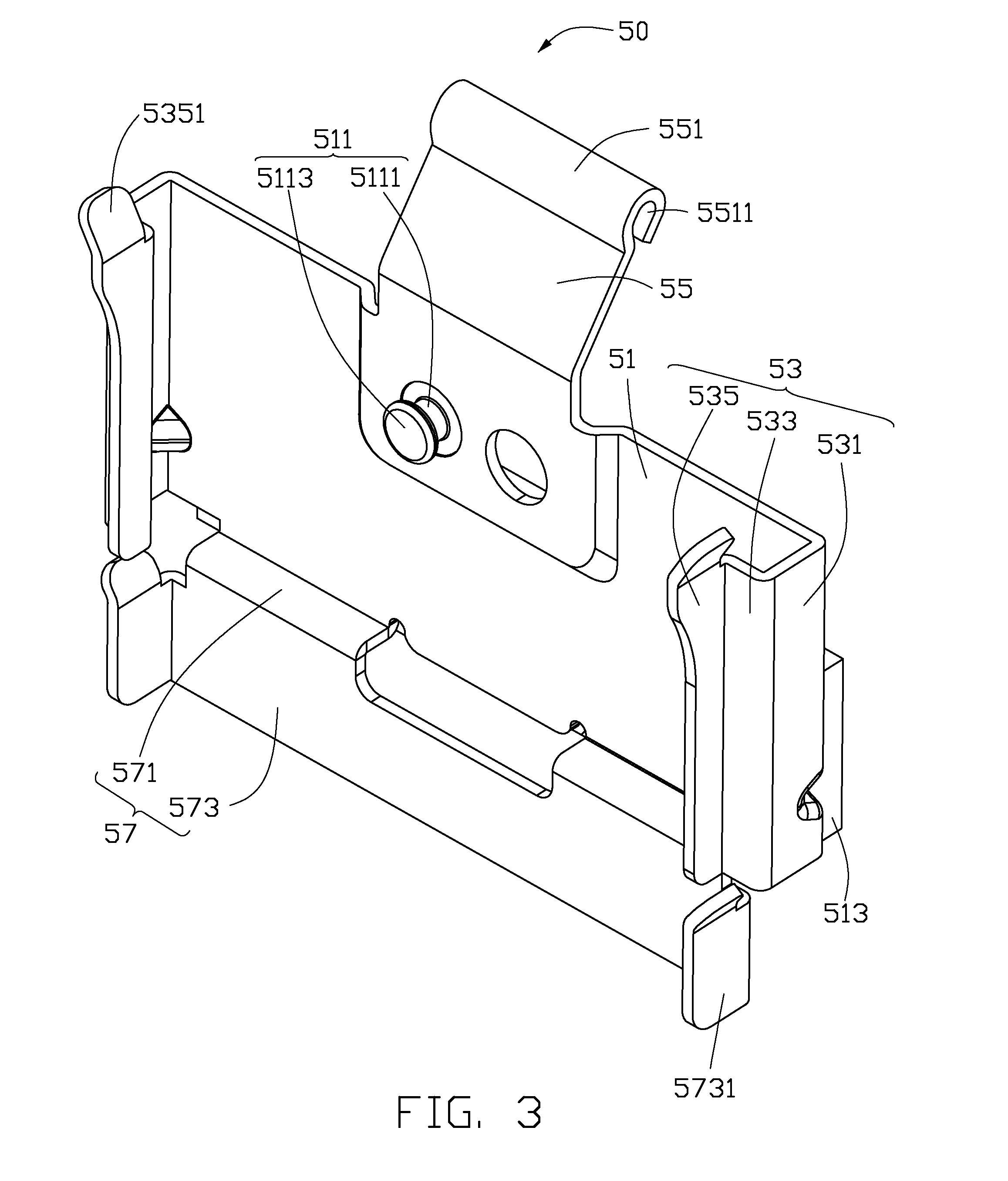
[0010] FIG. 3 is an isometric view of a mounting member of the mounting apparatus of FIG. 1.
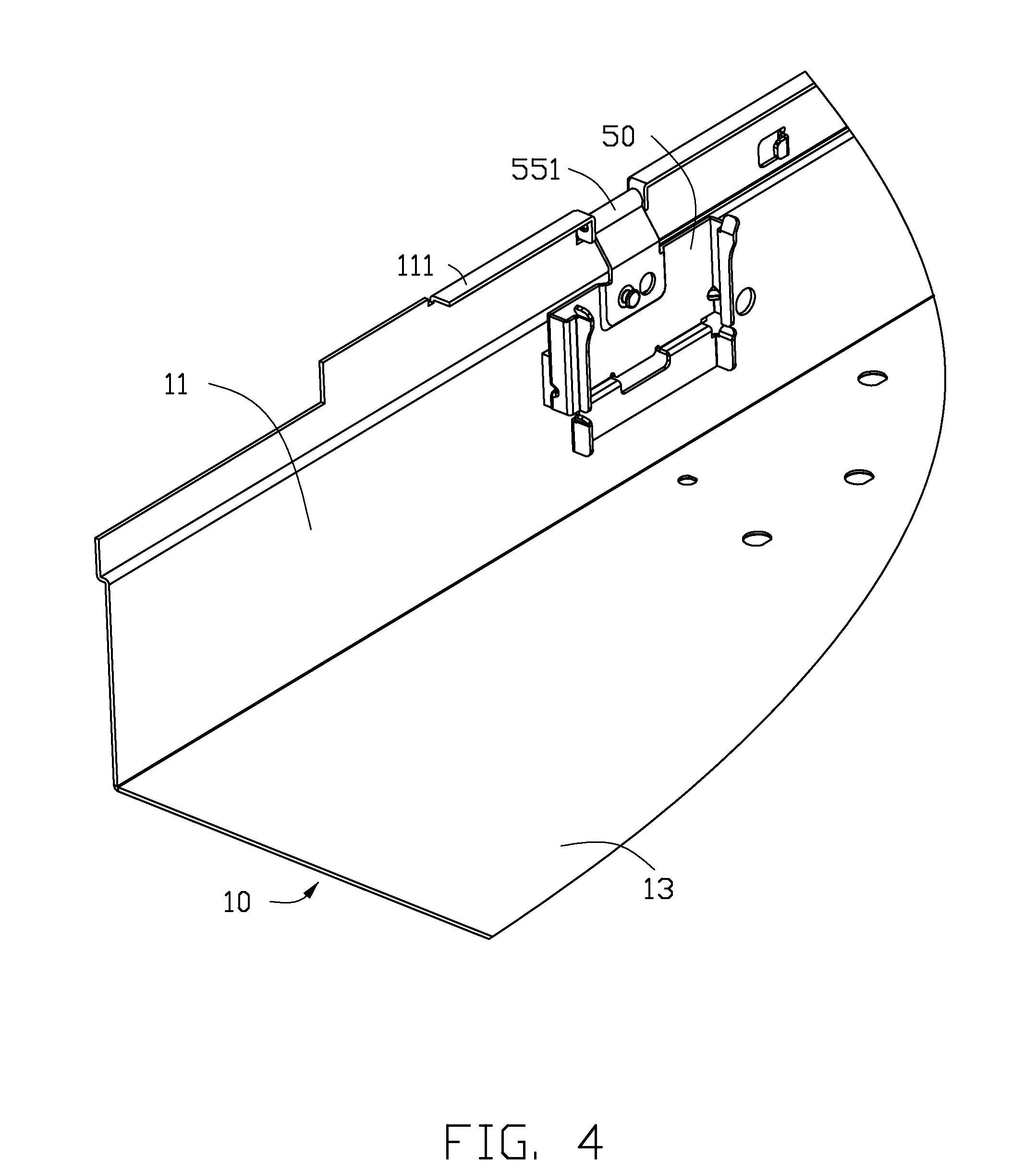
[0011] FIG. 4 is a cutaway, assembled view of the chassis and the mounting member of FIG. 1.
[0012] FIG. 5 is a partly assembled view of the fan module and the installation member of FIG. 1.
DETAILED DESCRIPTION
[0013] The disclosure is illustrated by way of example and not by way of limitation in the figures of the accompanying drawings in which like references indicate similar elements. It should be noted that references to "an" or "one" embodiment in this disclosure are not necessarily to the same embodiment, and such references mean at least one.
[0014] Referring to FIG. 2, a mounting apparatus in accordance with an embodiment comprises a chassis 10, an installation member 30, and two mounting members 50 secured to the chassis 10. The mounting apparatus is configured for securing a fan module 70 to the chassis 10. The fan module 70 comprises a plurality of fans 71, and a bracket 73 for receiving the plurality of fans 71. Two pivot portions 731 are placed on two opposite sides of the bracket 73.
[0015] The chassis 10 comprises two sidewalls 11 parallel to each other, and a bottom board 13 connected to the two sidewalls 11. A folding edge 111 extends inwardly from each of the two sidewalls 11. The folding edge 111 defines a cutout or a gap 113. Two installation pieces 115 substantially parallel to each other, extend from each of the two sidewalls 11 and are located on opposite sides of the gap 113. Each of the two installation pieces 115 defines an installation hole 1151. In one embodiment, each of the two installation pieces 115 is substantially perpendicular to each of the two sidewalls 11
[0016] The installation member 30 comprises an installation board 31 and two pivot pieces 33. The two pivot pieces 33 extend from two opposite ends of the installation board 31. Each of the two pivot pieces 33 defines a pivot hole 331. The pivot hole 331 comprises a wide portion 3311 and a narrow portion 3313 communicating with the wide portion 3311.
[0017] Referring to FIG. 3, each of two mounting members 50 comprises a connecting board 51, two clipping portions 53 located on two opposite sides of the connecting board 51, a pulling portion 55 extending from the connecting board 51, and a extending portion 57. In one embodiment, the two clipping portions 53, the pulling portion 55 and the extending portion 57 are arranged at the four sides of the connecting board 51.
[0018] A limiting portion 511 is located on the connecting board 51, and the limiting portion 511 comprises a neck portion 5111 extending from connecting board 51, and a head portion 5113 extending from the neck portion 5111. In one embodiment, a diameter of the neck portion 5111 is smaller than that of the head portion 5113. An abutting piece 513 is located on the connecting board 51, and is opposite to the limiting portion 511. The abutting piece 513 is adapted to absorb vibration.
[0019] Each of the two clipping portions 53 comprises a connecting portion 531 extending from the connecting board 51, a converting portion 533 extending from the connecting portion 531, and a gripping portion 535 extending from the converting portion 533. In one embodiment, the connecting portion 531 is substantially perpendicular to the connecting board 51, the converting portion 533 is substantially perpendicular to the connecting portion 531 and parallel to the connecting board 51, and the gripping portion 535 is substantially perpendicular to the converting portion 533 and the connecting board 51. A guiding portion 5351 extends upward from gripping portion 535.
[0020] An end of the pulling portion 55 forms a rotating portion 551, and a mounting hole 5511 is defined in the rotating portion 551. In one embodiment, an obtuse angle is defined between the pulling portion 55 and the connecting board 51.
[0021] The extending portion 57 comprises a bent portion 571 extending from the connecting board 51, and a leaning portion 573. In one embodiment, the bent portion 571 is substantially perpendicular to the connecting board 51 and the leaning portion 573 is substantially perpendicular to the bent portion 571. Two holding portions 5731 are located on two opposite sides of the leaning portion 573. In one embodiment, each of the two holding portions 5731 is substantially perpendicular to the leaning portion 573.
[0022] Referring to FIGS. 1 and 4, in assembly, the rotating member 551 of one of the two mounting members 50 is placed in the gap 113 of the chassis 10, the abutting piece 513 abuts the corresponding one of the two sidewalls 11. Two opposite end of the mounting hole 5511 are aligned with two installation holes 1151, and the locking member 80 extends through one of the two installation holes 1151, the mounting hole 5511 and another of the two installation holes 115 to pivotably secure one of the two mounting members 50 to one of the two sidewalls 11. Anther one of the two mounting members 50 is pivotably secured to another one of the two sidewalls 11 in the same manner.
[0023] In assembly, the installation board 31 is put up in a third direction (shown in FIG. 5). Each of the two pivot pieces 33 is adaptor to be rotated along the two pivot portions 731, until the pivot hole 331 aligns with the neck portion 5111 of each of the two mounting members 50. The fan module 70 descends along the guiding portion 5351 of the gripping portion 535. The neck portion 5111 extends through the wide portion 3311 of the pivot hole 331, until the neck portion 5111 engages in the narrow portion 3313. The installation board 31 is rotated in a fourth direction opposite to the third direction, until each of the two pivot pieces 33 engages with the bracket 73. Thereby, the fan module 70 is engaged between the two mounting members 50 to prevent from the fan module from moving in a first direction substantially perpendicularly to the two sidewalls 11, and in a plane which is substantially parallel with the two sidewalls 11. The neck portion 5111 is engaged in the narrow portion 3313 to prevent the fan module 70 from moving in a second direction substantially perpendicularly to the first direction and the plane. Each of the two pivot pieces 33 is located between the connecting board 51 and the bracket 73. The bracket 73 is clipped between two the gripping portions 535 and the two holding portions 5731, and the leaning portion 573 abuts the adjacent side of the bracket 73. In this way, the fan module 70 is secured to the chassis.
[0024] In disassembly, the installation board 31 is put up to rotate each of the two pivot pieces 33 along the third direction, until the pivot hole 331 aligns with the bottom board 13 of the chassis 10. The fan module 70 is moved away from the chassis 10. The neck portion 5111 is moved from the narrow portion 3313 to the wide portion 3311. Thus, the fan module 70 can be removed from the chassis 10.
[0025] It is to be understood, however, that even though numerous characteristics and advantages have been set forth in the foregoing description of embodiments, together with details of the structures and functions of the embodiments, the disclosure is illustrative only and changes may be made in detail, especially in the matters of shape, size, and arrangement of parts within the principles of the disclosure to the full extent indicated by the broad general meaning of the terms in which the appended claims are expressed.
* * * * *
D00000
D00001
D00002
D00003
D00004
D00005
XML
uspto.report is an independent third-party trademark research tool that is not affiliated, endorsed, or sponsored by the United States Patent and Trademark Office (USPTO) or any other governmental organization. The information provided by uspto.report is based on publicly available data at the time of writing and is intended for informational purposes only.
While we strive to provide accurate and up-to-date information, we do not guarantee the accuracy, completeness, reliability, or suitability of the information displayed on this site. The use of this site is at your own risk. Any reliance you place on such information is therefore strictly at your own risk.
All official trademark data, including owner information, should be verified by visiting the official USPTO website at www.uspto.gov. This site is not intended to replace professional legal advice and should not be used as a substitute for consulting with a legal professional who is knowledgeable about trademark law.