Flight Vehicle Fairing Having Vibration-Damping Blankets
Christenson; Justin ; et al.
U.S. patent application number 13/169295 was filed with the patent office on 2012-12-27 for flight vehicle fairing having vibration-damping blankets. This patent application is currently assigned to THE BOEING COMPANY. Invention is credited to Balamurugan R. Annamalai, Gary R. Chewning, Justin Christenson, Jason Alexander Gordon, Herbert L. Hoffman, Justin D. Kearns, Alan Edgar Landmann, Juhn-Shyue Lin, Hugh Poling, Adrian Viisoreanu.
| Application Number | 20120325966 13/169295 |
| Document ID | / |
| Family ID | 46466856 |
| Filed Date | 2012-12-27 |


| United States Patent Application | 20120325966 |
| Kind Code | A1 |
| Christenson; Justin ; et al. | December 27, 2012 |
Flight Vehicle Fairing Having Vibration-Damping Blankets
Abstract
Vibration-damping blankets are attached to the back surfaces of fairing panels of a flight vehicle (e.g., an aircraft or spacecraft) to reduce vibration, fatigue, structure and airborne transmitted energy, and cabin noise. In one case, the flight vehicle fairing has an exterior comprising exterior surfaces of a multiplicity of removable panels. A method of retrofitting the flight vehicle with vibration-damping blankets comprises: removing a panel from the flight vehicle exterior; attaching a vibration-damping blanket to a back surface of the removed panel; and installing the panel with attached vibration-damping blanket on the flight vehicle with the exterior surface of the panel forming part of the flight vehicle exterior. In one embodiment, the vibration-damping blanket comprises polymeric (e.g., aromatic polyamide) fibers in a nonwoven structure.
| Inventors: | Christenson; Justin; (Mountlake Terrace, WA) ; Hoffman; Herbert L.; (Seattle, WA) ; Lin; Juhn-Shyue; (Renton, WA) ; Chewning; Gary R.; (Woodinville, WA) ; Landmann; Alan Edgar; (Woodinville, WA) ; Viisoreanu; Adrian; (Kent, WA) ; Poling; Hugh; (Seattle, WA) ; Annamalai; Balamurugan R.; (Snohomish, WA) ; Kearns; Justin D.; (Seattle, WA) ; Gordon; Jason Alexander; (Long Beach, CA) |
| Assignee: | THE BOEING COMPANY Irvine CA |
| Family ID: | 46466856 |
| Appl. No.: | 13/169295 |
| Filed: | June 27, 2011 |
| Current U.S. Class: | 244/129.1 ; 29/402.04; 29/428 |
| Current CPC Class: | B64C 1/40 20130101; Y02T 50/40 20130101; Y10T 29/49723 20150115; Y02T 50/46 20130101; B64C 1/26 20130101; Y10T 29/49826 20150115 |
| Class at Publication: | 244/129.1 ; 29/402.04; 29/428 |
| International Class: | B64C 1/00 20060101 B64C001/00; B23P 11/00 20060101 B23P011/00; B23P 6/00 20060101 B23P006/00 |
Claims
1. A method for retrofitting a flight vehicle fairing having an exterior comprising an exterior surface of a removable panel, comprising: removing said panel from said fairing; attaching a vibration-damping blanket to a back surface of said removed panel; and installing said panel with attached vibration-damping blanket on said fairing with said exterior surface of said panel forming part of the fairing exterior.
2. The method as recited in claim 1, wherein said vibration-damping blanket comprises fibers in a nonwoven structure.
3. The method as recited in claim 2, wherein the fibers are made of polymeric material.
4. The method as recited in claim 3, wherein said polymeric material comprises aromatic polyamide.
5. The method as recited in claim 1, further comprising treating said vibration-damping blanket with water repellant additive.
6. The method as recited in claim 1, wherein said fairing comprises a pair of wheel wells, said panel being located aft of the wheel wells.
7. The method as recited in claim 1, wherein said failing is a component of an aircraft.
8. The method as recited in claim 1, wherein said fairing is a component of a spacecraft.
9. A method for assembling a fairing of a flight vehicle, comprising: attaching a vibration-damping blanket to a back surface of a panel; and fastening said panel with attached vibration-damping blanket to said fairing with said exterior surface of said panel forming part of the fairing exterior.
10. The method as recited in claim 9, wherein said vibration-damping blanket comprises fibers in a nonwoven structure.
11. The method as recited in claim 10, wherein the fibers are made of polymeric material.
12. The method as recited in claim 11, wherein said polymeric material comprises aromatic polyamide.
13. The method as recited in claim 9, wherein said fairing is a component of an aircraft or a spacecraft.
14. The method as recited in claim 13, wherein said fairing comprises a pair of wheel wells, said panel being located aft of the wheel wells.
15. A fairing for a flight vehicle comprising a multiplicity of panels, each panel having an exterior surface that forms a part of an exterior of the fairing, wherein at least one of said panels has a vibration-damping blanket attached to a back surface thereof.
16. The fairing as recited in claim 15, wherein said vibration-damping blanket comprises fibers in a nonwoven structure, said fibers being made of polymeric material.
17. The fairing as recited in claim 16, wherein said polymeric material comprises aromatic polyamide.
18. The fairing as recited in claim 15, wherein said vibration-damping blanket is water repellant.
19. The failing as recited in claim 15, further comprising a pair of wheel wells, said panel being located aft of the wheel wells.
20. The fairing as recited in claim 15, wherein said flight vehicle is an aircraft or a spacecraft.
Description
BACKGROUND
[0001] This disclosure generally relates to systems and methods for reducing or minimizing vibrations in the fairing of a flight vehicle, such as an aircraft or spacecraft, thereby also reducing noise and fatigue caused by such vibrations.
[0002] Aircraft, spacecraft and other flight vehicles often experience substantial vibrations, noise and fatigue in fairings and, in particular, in wing-to-body fairings which are attached between the wings and body of the aircraft, spacecraft or other flight vehicle. Some prior art devices may have involved heavy, complex, excessive parts and/or expensive noise- and vibration-damping devices in an effort to reduce vibrations, noise and fatigue. However, many of these prior art devices do not sufficiently reduce noise, vibration and/or fatigue, and/or may lead to increased weight, increased complexity, an increased number of parts, an increased cost, and/or other issues. For example, in the past insulation blankets have been added to aircraft cabins in order to reduce the cabin noise to acceptable levels. These blankets added weight to the aircraft.
[0003] In the case of fairings comprising a multiplicity of panels fastened to a support structure that is part of the flight vehicle, fairing panel vibration may additionally cause panels to loosen.
[0004] There is a need for a method of constructing fairings that reduces vibration, fatigue and resultant cabin noise by dissipational damping of vibrational energy and its conversion to heat energy. There is also a need to solve the problem of fairing panels vibrating and loosening.
SUMMARY
[0005] In accordance with the embodiments disclosed hereinafter, vibration-damping blankets are sufficiently attached to the back surfaces of fairing panels of a flight vehicle to reduce vibration, fatigue, structure and airborne transmitted energy, and cabin noise. This can be done during assembly of the flight vehicle or during retrofitting of existing flight vehicles. In the disclosed embodiments, the blankets comprise polymeric (e.g., aromatic polyamide) fibers in a nonwoven structure onto which an adhesive backing is applied for easy installation. However, the blankets may be constructed in other ways and with other materials such that a similar vibration-damping effect can be achieved.
[0006] One aspect of the invention is a method for retrofitting a flight vehicle fairing comprising an assembly of any number of removable panels by adhering vibration-damping blankets to the back surfaces of all or one or more selected panels. The method comprises removing a panel from the fairing exterior; attaching a vibration-damping blanket to a back surface of the removed panel; and installing the panel with attached vibration-damping blanket on the fairing with the exterior surface of the panel forming part of the fairing exterior.
[0007] Another aspect of the invention is a method for assembling a fairing of a flight vehicle. The method comprises attaching a vibration-damping blanket to a back surface of a panel; and fastening the panel with attached vibration-damping blanket to the fairing with the exterior surface of the panel forming part of the fairing exterior.
[0008] A further aspect of the invention is a fairing for a flight vehicle comprising a multiplicity of panels, each panel having an exterior surface that forms a part of an exterior of the fairing, wherein at least one of the panels has a vibration-damping blanket attached to a back surface thereof.
[0009] Other aspects of the invention are disclosed and claimed below.
BRIEF DESCRIPTION OF THE DRAWINGS
[0010] FIG. 1 is a diagram showing a bottom isometric view of one embodiment of a wing-to-body fairing attached between a body and wing of an aircraft.
[0011] FIG. 2 is a diagram showing a bottom isometric view of the wing-to-body fairing of FIG. 1 separated from the aircraft.
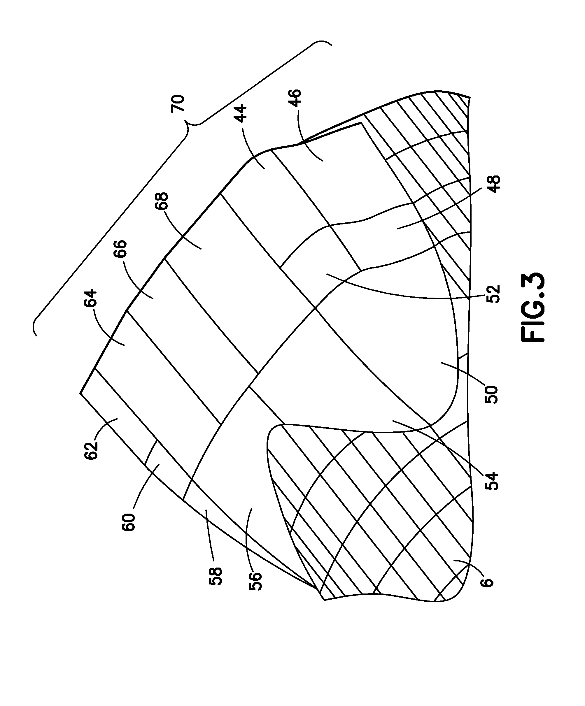
[0012] FIG. 3 is a diagram showing fairing panels located aft of the wheel wells of the wing-to-body fairing of FIG. 2.
[0013] FIG. 4 is a diagram showing a cross-sectional view of a known wing-to-body fairing panel disclosed in U.S. Patent Application Pub. No. 2009/0184206.
[0014] FIG. 5 is a diagram showing a cross-sectional view of a wing-to-body fairing panel equipped with a vibration-damping blanket in accordance with one embodiment of the invention.
[0015] Reference will hereinafter be made to the drawings in which similar elements in different drawings bear the same reference numerals.
DETAILED DESCRIPTION
[0016] FIG. 1 shows one embodiment of a wing-to-body fairing 4 attached between a body 6 and wings 8 of an aircraft 2. The wing-to-body fairing 4 may be attached to body 6 utilizing fasteners 10 and/or other attachment mechanisms.
[0017] FIG. 2 shows the wing-to-body fairing 4 of FIG. 1 separated from the aircraft 2. The fairing 4 comprises a multiplicity of panels 12 attached to a support structure, which support structure in turn is a lattice attached to the body of the flight vehicle. The support structure is not depicted in FIG. 2. However, the use and construction of such a support structure is well known. For example, the panel support structure may be made of aluminum. The fairing 4 has openings for the wings and also has wheel wells 14 which receive the landing wheels when the landing gear is not deployed during flight.
[0018] FIG. 3 shows the aft portion 70 of a typical wing-to-body fairing (WTBF) assembly comprising a multiplicity of removable panels fastened to a lattice or similar support structure. More specifically, the aft portion 70 comprises a multiplicity of panels located aft of the wheel wells (see items 14 in FIG. 2) of the fairing. The panels of the aft portion 70 of the fairing depicted in FIG. 3 are respectively numbered 44, 46, 48, 50, 52, 54, 56, 58 60, 62, 64, 66 and 68. Although vibration-damping blankets can be attached to the back surfaces of all of these panels, in accordance with one embodiment, such blankets are attached to the back surfaces of at least panels 50, 54, 56, 58, 66 and 68.
[0019] FIG. 4 shows a cross-sectional view of a prior art WTBF panel 12 which has not been retrofitted in accordance with the teaching herein, whereas FIG. 5 shows the same view, except with a vibration-damping blanket 36 attached, e.g., by a layer of adhesive 34, to the back surface of the prior art panel 12. In accordance with the present teaching, vibration-damping blankets can be attached to selected or all fairing panels, either during original production of the flight vehicle or during retrofitting of an existing flight vehicle.
[0020] As shown in FIG. 4, prior art WTBF panel 12 comprises a honeycomb center 18 sandwiched between front and rear panel walls 25 and 26, respectively. The front panel wall 25 is planar, while the rear panel wall 26 is not planar. A central portion of rear panel wall 26 forms a plateau with a generally flat surface on the back surface of the panel. In cooperation, panel walls 25 and 26 form a cavity for receiving the honeycomb center 18. Two adjacent layers 28 are laminated to each other and disposed along the perimeter of the panel 12. Portions of layers 28 are sandwiched between and laminated to respective portions of panel walls 25 and 26 to form a flange 30. The flange 30 is provided with a plurality of bushing inserts 32 which receive fasteners (not shown) for attaching panel 12 to the panel support structure (not shown). Other portions of layers 28 are laminated to corresponding portions of rear panel wall 26 and provide increased strength and rigidity to the panel structure, including the plateau. Each of panel walls 25, 26 and layers 28 may consist of multiple plies of fiberglass or other fiber-reinforced composite material. The honeycomb center 18 is attached to panel walls 25, 26 and to the innermost of layers 28 by a layer of structural adhesive 24.
[0021] The honeycomb center 18 comprises an open-cell pattern 22 and may be made of any of the following materials: aluminum, Nomex.RTM., metal, syntactic foam, a composite material, or other types of material. The walls of the open-cell pattern have holes 20 that allow flow communication between adjacent cells. The cells are partially or fully filled with a vibration-damping foam material and/or vibration-damping particles (indicated by speckling in FIGS. 4 and 5), as disclosed in U.S. Patent Application Pub. No. US 2009/0184200. The above-described honeycomb structure, partially or fully filled with foam and/or particles, is intended to make the panel more resistant to vibration.
[0022] The embodiment depicted in FIG. 5 improves upon the prior art panel by further damping panel vibration. This is accomplished by attaching a vibration-damping blanket 36 to the back surface of the panel 12. For the particular panel depicted in FIG. 5, the blanket 36 is attached to the generally flat surface of the plateau formed by the rear panel wall 26. Blanket 36 is attached to the rear panel wall 26 by means of a layer of adhesive 34.
[0023] Testing has shown that blankets comprising Nomex.RTM. aramid staple fibers arranged in a 1/2- and 1-inch-thick nonwoven structure are effective in damping vibrations in a typical wing-to-body fairing. The overall dBA reduction was determined by summing the noise spectra over the critical frequencies of 315, 400 and 500 Hz 1/3 octave bands. Nomex.RTM. is a family of aromatic polyamide (aramid) fibers. Any other blanket having equivalent vibration-damping properties can be used in the alternative. Preferably, the fibers of the vibration-damping blanket have the capability to repel water. Water-repellant Nomex.RTM. blankets bearing the product designation MC8-4591-B18 are commercially available. These blankets are sold with pre-applied adhesive on one side, the adhesive being covered by a peel-away release film. After the release film has been peeled off to expose the adhesive, the side of the blanket having adhesive thereon can be pressed against a fairing panel to adhere the blanket to the panel.
[0024] In accordance with one embodiment, a multi-panel fairing of an existing flight vehicle can be retrofitted with vibration-damping blankets. The exterior of the flight vehicle fairing comprises the exterior surfaces of a multiplicity of removable panels. All or some of the removable panels can be retrofitted with vibration-damping blankets on their back surfaces to reduce fairing vibration, fatigue and noise. The fairing may be a component of an aircraft, spacecraft or other flight vehicle. Testing has shown that the application of vibration-damping blankets to the back surfaces of at least selected panels located aft of the fair wheel wells is advantageous. The retrofitting method for each removable panel comprises the following steps: (1) removing the panel from the fairing; (2) attaching a vibration-damping blanket to a back surface of said removed panel by means of a layer of adhesive; and (3) installing the panel with attached vibration-damping blanket on the fairing with the exterior surface of the panel forming part of the fairing exterior. In one embodiment, the vibration-damping blanket comprises aromatic polyamide fibers in a nonwoven structure, which fibers have been treated with water-repellant agent.
[0025] In accordance with another embodiment, vibration-damping blankets can be attached to the back surfaces of a multiplicity of panels of a multi-panel fairing during original assembly of the flight vehicle. Again this can be accomplished by adhering water-repellant Nomex.RTM. blankets to the back surfaces of selected fairing panels.
[0026] Testing has shown that the application of Nomex.RTM. blankets (treated with water repellant) to panels of a typical wing-to-body fairing of an airplane is an acceptable solution in terms of weight, damping benefits, cabin noise reduction, ease of retrofit for a large in-service fleet, ease to put into production in terms of build time and cost while also ensuring that the aircraft loft lines do not alter, and ability to withstand an arduous environment/life-cycle considerations.
[0027] While the invention has been described with reference to various embodiments, it will be understood by those skilled in the art that various changes may be made and equivalents may be substituted for elements thereof without departing from the scope of the invention. In addition, many modifications may be made to adapt a particular situation to the teachings of the invention without departing from the essential scope thereof. Therefore it is intended that the invention not be limited to the particular embodiments disclosed herein.
* * * * *
D00000
D00001
D00002
D00003
XML
uspto.report is an independent third-party trademark research tool that is not affiliated, endorsed, or sponsored by the United States Patent and Trademark Office (USPTO) or any other governmental organization. The information provided by uspto.report is based on publicly available data at the time of writing and is intended for informational purposes only.
While we strive to provide accurate and up-to-date information, we do not guarantee the accuracy, completeness, reliability, or suitability of the information displayed on this site. The use of this site is at your own risk. Any reliance you place on such information is therefore strictly at your own risk.
All official trademark data, including owner information, should be verified by visiting the official USPTO website at www.uspto.gov. This site is not intended to replace professional legal advice and should not be used as a substitute for consulting with a legal professional who is knowledgeable about trademark law.