Devices For Dispensing And Displaying Products And Package Assemblies For Use With The Same
Bates; Aaron L. ; et al.
U.S. patent application number 13/581486 was filed with the patent office on 2012-12-27 for devices for dispensing and displaying products and package assemblies for use with the same. This patent application is currently assigned to MEADWESTVACO CORPORATION. Invention is credited to Ryan A. Bailey, Aaron L. Bates, Caleb S. Loftin, Laurel Thomas.
| Application Number | 20120325839 13/581486 |
| Document ID | / |
| Family ID | 44542528 |
| Filed Date | 2012-12-27 |


View All Diagrams
| United States Patent Application | 20120325839 |
| Kind Code | A1 |
| Bates; Aaron L. ; et al. | December 27, 2012 |
DEVICES FOR DISPENSING AND DISPLAYING PRODUCTS AND PACKAGE ASSEMBLIES FOR USE WITH THE SAME
Abstract
A device for dispensing and displaying products is disclosed. The device comprises: a package assembly having an outer sleeve with at least one aperture formed therein and a product retaining insert slidably engaged within the outer sleeve; a frame having an upper support deck and a product display area; and an engagement feature extending from the frame. When the package assembly is slid longitudinally onto the upper support deck of the frame, the engagement feature extends through the aperture formed in the outer sleeve and engages with the product retaining insert such that the products inside the package assembly are at least partially dispensed from the package into the product display area.
| Inventors: | Bates; Aaron L.; (Moseley, VA) ; Loftin; Caleb S.; (Richmond, VA) ; Bailey; Ryan A.; (Richmond, VA) ; Thomas; Laurel; (Portland, OR) |
| Assignee: | MEADWESTVACO CORPORATION Richmond VA |
| Family ID: | 44542528 |
| Appl. No.: | 13/581486 |
| Filed: | March 1, 2011 |
| PCT Filed: | March 1, 2011 |
| PCT NO: | PCT/US11/26621 |
| 371 Date: | August 28, 2012 |
Related U.S. Patent Documents
| Application Number | Filing Date | Patent Number | ||
|---|---|---|---|---|
| 61310238 | Mar 3, 2010 | |||
| Current U.S. Class: | 221/194 |
| Current CPC Class: | B65D 5/728 20130101; B65D 5/725 20130101; A47F 1/087 20130101 |
| Class at Publication: | 221/194 |
| International Class: | B65H 3/00 20060101 B65H003/00 |
Claims
1. A system for shipping, dispensing and displaying a plurality of products comprising: (a) a package assembly including: (i) an outer sleeve having at least one aperture formed therein; and (ii) a product retaining insert slidably engaged within the outer sleeve, wherein the outer sleeve and the product retaining insert define a shipping compartment for the plurality of products; (b) a frame having longitudinally opposed front and rear end sections and including an upper support deck extending at least partially between the front and rear end sections and below which a product display area is provided; and (c) an engagement feature extending from the frame, wherein when the package assembly is slid longitudinally onto the upper support deck of the frame towards the rear end section to a first position, the engagement feature extends through the aperture formed in the outer sleeve and engages with the product retaining insert such that when the outer sleeve is slid longitudinally towards the front end section to a second position, the product retaining insert is restrained in the first position enabling the products to be at least partially dispensed from the package into the product display area.
2. The system of claim 1, wherein the product retaining insert includes a bottom panel having a hinged door formed therein which is arranged such that the door opens when the outer sleeve is slid longitudinally to the second position thereby allowing the products to be at least partially dispensed from the package into the product display area.
3. The system of claim 1, wherein the product retaining insert includes a U-shaped transverse cross-section.
4. The system of claim 1, wherein the frame further includes a lower display shelf.
5. The system of claim 4, wherein the lower display shelf includes a lane divider to create two display channels within the product display area.
6. The system of claim 4, wherein the lower display shelf includes an upwardly extending rib for guiding products to the front end section of the frame.
7. The system of claim 1, wherein the frame further includes a rear wall which is configured to guide products to the product display area.
8. The system of claim 1, wherein the upper support deck is inclined at an acute angle with respect to a horizontal plane.
9. The system of claim 1, wherein the engagement feature is formed in the upper support deck of the frame.
10. The system of claim 1, wherein the frame further includes first and second laterally opposed side walls.
11. The system of claim 10, wherein the first and second laterally opposed side walls of the frame are adapted and configured for guiding the package as it is moved longitudinally along the upper support deck.
12. The system of claim 10, wherein the engagement feature is associated with at least one of the first and second laterally opposed side walls of the frame.
13. The system of claim 1, wherein the upper support deck includes two longitudinally extending rails.
14. The system of claim 1, further comprising means for securing the frame to a vertical wall or to a horizontal shelf.
15. The system of claim 1, wherein the front end section of the frame includes means for displaying product related indicia.
16. A package assembly comprising: (a) an outer sleeve having at least one aperture formed therein, and (b) a product retaining insert slidably engaged within the outer sleeve so that the outer sleeve and the insert are slidingly movable with respect to each other along a sleeve axis of the outer sleeve, the insert comprising at least one engaging edge disposed such that the at least one engaging edge is accessible from an outside of the outer sleeve through the at least one aperture, the engaging edge extending transversely of the sleeve axis.
17. The package assembly of claim 16, wherein the aperture has first and second opposed end edges disposed along the sleeve axis, and the engaging edge is disposed between the first and second end edges when the insert is in a fully received position.
18. The package assembly of claim 17, wherein the outer sleeve has a closed end and an opposed open end, the first end edge of the aperture is disposed closer to the closed end than the second end edge, the engaging edge is disposed at a distance (D1) from the second end edge when the insert is in a fully received position, and the distance is no less than a dimension (D2) of an access opening defined in the insert.
19. The package assembly of claim 18, wherein the insert comprises first and second adjacent walls, the first wall being disposed to close the open end of the outer sleeve when the insert is in the fully received position, and the access opening is defined in the second wall proximate the first wall.
20. The package assembly of claim 19, wherein the engaging edge is provided by the second wall.
Description
BACKGROUND OF THE DISCLOSURE
[0001] 1. Field of the Disclosure
[0002] The dispensing and display devices for use at point-of-sale (POS) locations are disclosed. The disclosure relates to a display device which includes a frame that is adapted and configured for receiving a carton or package containing a plurality of products on an upper deck of the display device and an engagement feature for facilitating the opening of the carton and the dispensing of the products sequentially from the carton into a lower display area. The disclosure also relates to a system that includes a dispensing and display device, such as the aforementioned, and a package or carton of articles which is specially adapted for use with the dispensing and display device, the package or carton including an inner product retaining insert slidably positioned within and an outer sleeve. The disclosure further relates to blanks for use in forming cartons or packages adapted for use with the aforementioned dispensing and display device.
[0003] 2. Background of the Related Art
[0004] At point-of-sale (POS) or display units in retail outlets/locations, it is convenient to present articles and products in an eye-catching and easily accessible manner. These POS or display units also act as a storage area for articles and products. As such, it is desirable to maximize the amount of storage space utilized, whilst at the same time enabling a customer to easily select and take products away for purchase. To achieve this, as articles are removed, it is desirable for the shelf to forward fill to present the next stored article for easy selection by a customer. Some dispensers have sprung-biased mechanisms that push articles forward; other known display devices use gravity feed mechanisms to cause articles to flow to the forward-most sale position. One such dispensing device is disclosed in U.S. Pat. No. 5,396,997 wherein a dispensing device has upper and lower jar guides and a plurality of glass jar containers are loaded on their sides through a container loading area. The dispenser racks successively feed one container at a time to the container dispensing area to thereby provide a self-feeding and self-facing storage, dispensing and display system.
[0005] A drawback of systems, such as that disclosed in U.S. Pat. No. 5,396,997, is that loading of the dispensing device is done manually and individually. In U.S. Pat. No. 5,396,997, a rotatable door panel is provided so that loading occurs through the openable upper jar guide. As such articles are fed one at a time into the upper jar guide. Loading in this manner is slow, and therefore, time-consuming. Additionally, the products being displayed in the dispensing device are usually transported to a retail outlet in a carton or box containing a number of such articles. Therefore, if the dispensing device is not capable of holding all of the articles contained in the delivered carton or box, then any article that could not be loaded into the dispensing device need to be stored elsewhere in the retail outlet in the partially emptied carton or box, until such time as the dispensing device can accommodate those articles.
[0006] It is therefore desirable to improve the manner in which the filling of the dispensing devices takes place. It is desirable that the filling is quick, enables full cartons of delivered goods to be accommodated in the dispensing device. Additionally, it is desirable that the requirement for storing any extra article that cannot be displayed may be avoided.
[0007] Furthermore, it is desirable that such dispensing devices are made from a minimum amount of material.
[0008] It is also desirable that such dispensing devices are as eye-catching as possible to the consumers and contain branding, advertising and/or marketing material for this purpose. Since the advertising and branding materials and graphics are frequently changed and altered in line with trends and promotions, it is also desirable that the dispensing devices are adaptable to facilitate quick changeovers in the branding, advertising and marketing graphics displayed thereon.
SUMMARY OF THE DISCLOSURE
[0009] A system for shipping, dispensing and displaying a plurality of products is disclosed that includes a package assembly, a frame, and an engagement feature extending from the framer.
[0010] The package assembly has an outer sleeve with at least one aperture formed therein and a product retaining insert slidably engaged within the outer sleeve. The outer sleeve and the product retaining insert define a shipping compartment for the plurality of products.
[0011] The frame that has longitudinally opposed front and rear end sections and includes an upper support deck extending at least partially between the front and rear end sections and below which a product display area is provided. In one embodiment of the present disclosure, the upper support deck is inclined at an acute angle with respect to a horizontal plane. It is presently envisioned that in certain embodiments of the present disclosure, the upper support deck includes two longitudinally extending rails. The frame may also include first and second laterally opposed side walls, which in certain constructions are adapted and configured for guiding the package as it is moved longitudinally along the upper support deck.
[0012] When the package assembly is slid longitudinally onto the upper support deck of the frame towards the rear end section to a first position, the engagement feature extends through the aperture formed in the outer sleeve of the package assembly and engages with the product retaining insert. As a result, when the outer sleeve is slid longitudinally towards the front end section to a second position, the product retaining insert is restrained in the first position which enables the products to be at least partially dispensed from the package into the product display area. Those skilled in the art will readily appreciate that the engagement feature and the frame may be a unitary structure or separate parts which are attached using a variety of known techniques.
[0013] In certain constructions, it is envisioned that the product retaining insert includes a bottom panel that has a hinged door formed therein. The hinged door is arranged and configured such that the door opens when the outer sleeve is slid longitudinally to the second position, thereby allowing the products to be at least partially dispensed from the package into the product display area. Alternatively, in certain constructions, the transverse cross-section of the product retaining insert is U-shaped.
[0014] In one embodiment of the present disclosure, the frame includes a lower display shelf. In certain constructions, the lower display shelf includes a lane divider to create two display channels within the product display area. Still further, the lower display shelf may include an upwardly extending rib for guiding products to the front end section of the frame.
[0015] It is also envisioned that the frame may include a rear wall which is configured to guide products to the product display area. In certain constructions, a guide ramp may be formed as part of the rear wall of the frame. In alternative constructions, the guide ramp may be formed as part of the lower display shelf.
[0016] In certain construction embodiments of the present disclosure, the engagement feature may be formed in the upper support deck. Alternatively, the engagement feature may be formed in or extend from either of both lateral side walls of the frame.
[0017] It is envisioned that in certain embodiments of the present disclosure, the frame includes a mechanism for securing the frame to a vertical wall. Moreover, the frame may include a mechanism for securing the frame to a horizontal shelf. It is also envisioned that the front end section of the frame may include structure or a mechanism for displaying product related indicia.
[0018] The present disclosure is also directed to a package assembly that includes an outer sleeve having at least one aperture formed therein, and a product retaining insert slidably engaged within the outer sleeve such that the outer sleeve and the insert are slidingly movable with respect to each other along a sleeve axis. The insert includes at least one engaging edge disposed such that the at least one engaging edge is accessible from an outside of the outer sleeve through the at least one aperture, the engaging edge extending transversely of the sleeve axis.
[0019] In one embodiment of the present disclosure, the aperture formed in the outer sleeve has first and second opposed end edges disposed along the sleeve axis, and the engaging edge of the insert is disposed or positioned between the first and second end edges when the insert is in a fully received position.
[0020] In certain constructions, the outer sleeve has a closed end and an opposed open end, and the first end edge of the aperture is disposed closer to the closed end than the second end edge. Moreover, the engaging edge of the insert is disposed at a distance (D1) from the second end edge, and the distance is no less than a dimension (D2) of an access opening defined in the insert.
[0021] In one construction of the present disclosure, the insert includes first and second adjacent walls, the first wall being disposed to close the open end of the outer sleeve when the insert is in the fully received position, and the access opening defined in the second wall proximate the first wall. In such a construction, it is envisioned that the engaging edge of the insert may be provided by the second wall.
[0022] These and other aspects of the present disclosure will become more readily apparent to those having ordinary skill in the art from the following detailed description taken in conjunction with the drawings.
BRIEF DESCRIPTION OF THE DRAWINGS
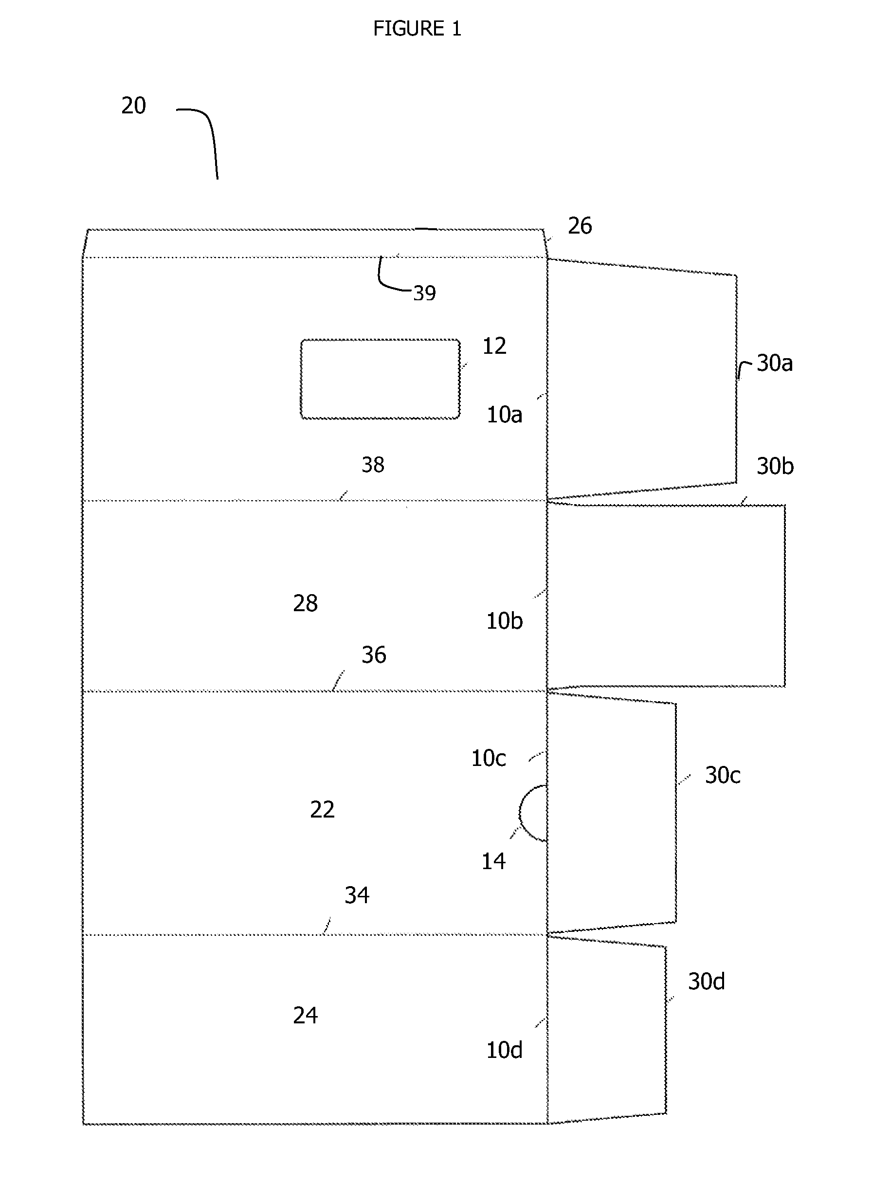
[0023] FIG. 1 is a blank for forming an outer sleeve for a package assembly constructed in accordance with a first embodiment of the present disclosure;
[0024] FIG. 2 is a perspective view of an outer sleeve for a packaging assembly of the present disclosure which has been constructed using the blank of FIG. 1;
[0025] FIG. 3 is a blank for a product retaining insert for a packaging assembly constructed in accordance with a first embodiment of the present disclosure;
[0026] FIG. 4 is a perspective view of a product retaining insert for a packaging assembly of the present disclosure which has been constructed using the blank of FIG. 3;
[0027] FIG. 5 is a perspective view of a packaging assembly which has been constructed in accordance with a first embodiment of the present disclosure using the outer sleeve of FIG. 2 and the product retaining insert of FIG. 4;
[0028] FIG. 6 is a perspective view taken from beneath a packaging assembly which has been constructed in accordance with a first embodiment of the present disclosure, wherein the outer sleeve has been moved longitudinally with respect to the product retaining insert thereby opening a door formed in the bottom of the product retaining insert;
[0029] FIG. 7 is a perspective view taken from the above the packaging assembly illustrated in FIG. 6;
[0030] FIG. 8 is a perspective view of frame constructed in accordance with a first embodiment of the display and dispensing device of the present disclosure;
[0031] FIG. 9 is a cross-sectional view taken along the longitudinal centerline of the frame illustrated in FIG. 8;
[0032] FIG. 10 is a cross-sectional view taken along the longitudinal centerline of the frame illustrated in FIG. 8 showing the packaging assembly located on the upper support deck in a first position;
[0033] FIG. 11 is a cross-sectional view taken along the longitudinal centerline of the frame illustrated in FIG. 8 showing the packaging assembly located on the upper support deck in a second position and wherein the products have been partially dispensed from the package assembly;
[0034] FIG. 12 is an exemplary product that may be dispensed and displayed using the devices and methods of the present disclosure; and
[0035] FIG. 13 provides a perspective view of a second embodiment of the packaging assembly of the present disclosure wherein the product retaining insert has a U-shaped lateral cross-section.
DETAILED DESCRIPTIONS OF THE DISCLOSURE
[0036] Detailed descriptions of several embodiments of the disclosed dispensing and display devices and packaging assemblies are discussed herein. It will be understood that the disclosed embodiments are merely examples of the way in which certain aspects of the disclosure can be implemented and they do not represent an exhaustive list of all of the ways the disclosure may be embodied. Indeed, it will be understood that the apparatus and cartons described herein may be embodied in various and alternative forms. The figures are not necessarily to scale, and some features may be exaggerated or minimized to show details of particular components. Well-known components, materials, or methods are not necessarily described in great detail in order to avoid obscuring the present disclosure. Any specific structural and functional details disclosed herein are not to be interpreted as limiting, but merely as a basis for the claims and as a representative basis for teaching one skilled in the art to variously employ the disclosure.
[0037] Referring now to FIGS. 1-7, shown therein is a packaging assembly 100 which has been constructed in accordance with one embodiment of the present disclosure. Package assembly 100 includes an outer sleeve 20 (see FIG. 2) and a product retaining insert 40 (see FIG. 4).
[0038] FIG. 1 provides an illustration of the carton blank used to construct outer sleeve 20. As shown therein, the carton blank includes: a top panel 22, a first side panel 24, a bottom panel 26, a second side panel 28, end closure flaps 30a-d, and glue flap 32. The main panels (the top panel 22, the first side panel 24, the bottom panel 26, and the second side panel 28) are hinged one to the next in series along fold lines 34, 36 and 38 respectively. The glue flap 32 is connected to the second side panel 26 along fold line 39. The end closure flaps 30a-c are hinged to opposite ends of the main panels along fold lines 10a-d respectively.
[0039] Referring to FIG. 2, the blank is foldable into outer sleeve 20 when the glue flap 32 is secured to the inner face of first side panel 24 and the end closure flaps 30a-d are secured in an overlapping, face contacting relationship. The end closure flaps 30a-d may be secured using adhesive or other suitable securing means including mechanical fastenings, to form a composite front end wall 30 (see FIGS. 5 and 7). As shown in FIG. 2, a fully formed outer sleeve 20 is formed which has one open end and one closed end.
[0040] Outer sleeve 20 has an elongated aperture 12 formed in bottom panel 26 and a weakened or perforated arcuate-shaped section 14 has been provided in top panel 22. The aperture 12 has a front end edge 15 and an opposed rear end edge 17 disposed along the sleeve axis X-X of the outer sleeve 20. The purpose and function of aperture 12 and perforated section 14 will be discussed in detail hereinbelow.
[0041] Referring to FIG. 3, which illustrates the blank used to construct product retaining insert 40. As shown therein, the carton blank includes: a top panel 42, a first side panel 44, a bottom panel 46, a second side panel 48, end closure flaps 50a-d, and glue flap 52. The main panels (top panel 42, first side panel 44, bottom panel 46, and second side panel 48) are hinged one to the next in series along fold lines 54, 56 and 58, respectively. The glue flap 52 is connected to the second side panel 46 along fold line 59. The end closure flaps 50a-d are hinged to opposite ends of the main panels along fold lines 60a-d respectively.
[0042] As shown in FIG. 4, the blank is foldable into product retaining insert 40 when the glue flap 52 is secured to the inner face of second side panel 48 and the end closure flaps 50a-d are secured in an overlapping, face contacting relationship. The end closure flaps 50a-d may be secured using adhesive or other suitable securing means including mechanical fastenings, to form a composite rear end wall 50 (see FIG. 4). As shown in FIG. 4, a fully formed product retaining insert 40 is formed which has one open end and one closed end.
[0043] Referring to FIG. 3, product retaining insert 40 has U-shaped perforation 62 formed in bottom panel 46 and an arcuate-shaped cutout 64 has been provided in top panel 42. Additionally, a door 66 has been formed in bottom panel 46 which is bounded by severance lines 68a-c, 69a, 69b, and fold line 60c. The severance line 68b extends transversely across the bottom panel 46 and is disposed substantially parallel to the fold line 60c. The severance lines 68a and 68c emanate from the opposite ends of the severance line 68b respectively extend toward the fold line 60c and terminate at respective points spaced from the fold line 60c. The severance lines 69a and 69b emanate from the respective terminal points of the severance lines 68a and 68c and extend to the fold line 60c. The severance lines 68a and 69a are disposed in alignment with the fold line 56; whereas the severance lines 68c and 69b are disposed in alignment with the fold line 58. The severance lines 69a and 69b may be less frangible than the other severance lines 68a-c. For example, the severance lines 68a-c are perforations; whereas the severance lines 69a and 69b are score lines. The purpose and function of U-shaped perforation 62, cutout 64, and door 66 will be discussed in detail hereinbelow.
[0044] Referring now to FIGS. 5-7, which illustrate the product retaining insert 40 slidably received within outer sleeve 20. In FIG. 5, the product retaining insert 40 has been completely inserted into the open end of the outer sleeve 20 such that its rear end wall 50 is aligned with the rear end of the outer sleeve 20. In such a configuration, the U-shaped perforation or slit 62 formed in the bottom panel 46 of the retaining insert 40 is visible through the aperture 12 formed in the bottom panel of the outer sleeve 20. As can be readily understood by those skilled in the art to which this application pertains, the outer sleeve 20 and the product retaining insert 40 cooperate to define a shipping compartment for a plurality of products.
[0045] In FIGS. 6 and 7, the product retaining insert 40 is only partially inserted into the outer sleeve 20 such that the rear end wall 50 is positioned well beyond the open end of the outer sleeve 20. In this configuration, the door 66 formed in the bottom panel 46 of the retaining insert 40 is exposed and drops open. In FIG. 6, the door 66 is illustrated as being folded down along a fold line 71 which is substantially parallel to the fold line 60c and which extends between the respective terminal points of the severance lines 68a and 68c. The fold line 71 may be either naturally created as the door 66 is folded down or pre-formed when the blank 40 is cut. The severance lines 69a and 69b remain unbroken in such an embodiment. Alternatively, the door 66 may be folded down along the fold line 60c regardless of a pre-formed fold line 71. In such an alternative embodiment, the severance lines 69a and 69c are broken along with the other severance lines 68a-c.
[0046] Referring now to FIGS. 8 and 9, there is illustrated a frame 70 and an engagement feature 90, which have been constructed in accordance with one embodiment of the present disclosure. The frame 70 has longitudinally opposed front and rear end sections, 72 and 74 respectively, and includes an upper support deck 76 that extends partially between the front and rear end sections 72/74 of the frame 70. The upper support deck 76 is inclined at an acute angle with respect to a horizontal plane and slopes downward as it approaches the rear end section 74 of the frame 70. A product display area 80 is provided below the upper support deck 76. Those skilled in the art will readily appreciate that the upper support deck 76 may include two longitudinally extending rails, rather than one or in addition to a full width platform, without departing from the scope of the present disclosure.
[0047] The frame 70 may also includes first and second laterally opposed side walls 78a-b, which are adapted and configured for guiding the package assembly 100 as it is moved longitudinally along the upper support deck 76.
[0048] The frame 70 may also include an inclined lower display shelf 82. The lower display shelf 82 slopes downward in the direction towards the front end section 72 of the frame 70. A rib 84 extends upwards from the lower display shelf 82 and is used to guide products to the front end section 72 of the frame 70. In certain embodiments of the present disclosure, products may have an uneven distribution of weight, and therefore, would tend to bind up between the laterally opposed side walls 78a-b of the frame 70 or become misaligned when rolling down the lower display shelf 82. An exemplary product "P" having an uneven distribution of weight is shown in FIG. 12. This product "P" has been provided with a recess (R) or groove in its outer periphery. The rib 84 formed is the lower display shelf is configured to engage within the recess (R) formed in product "P" and keeps the product properly aligned as it rolls towards the front end section 72 of the frame 70. Additionally, those skilled in the art will readily appreciate that the lower display shelf 82 may include a lane divider if it is desirable to create two display channels within the product display area.
[0049] The frame 70 may also include a rear wall 86 which is configured to guide products to the product display area. In the construction shown in FIG. 9, a guide ramp 88 is formed as part of the rear wall 86 and lower display shelf 82 of the frame 70.
[0050] The engagement feature 90 extends upwardly from the upper support deck 76 and is positioned along the longitudinal centerline of the frame 70. As shown in FIG. 8, the engagement feature 90 is formed as part of the upper support deck 76 (i.e., it's a monolithic structure). However, those skilled in the art will readily appreciate that the engagement feature 90 may be a separate part which is removable or modular and may be secured to the upper support deck 76 using a variety of means, including, but not limited to, mechanical fasteners, adhesives, or welding techniques.
[0051] With continuing reference to FIGS. 8 and 9, engagement feature 90 is elongated and has a front inclined surface 92, a flat top surface 94, and a rear face 96 which is perpendicular to top surface 94.
[0052] Refer now to FIGS. 10 and 11, which illustrate the operation of the display and dispensing device of the present disclosure. First a packaging assembly, for example, the previously described packaging assembly 100, is slid onto the upper support deck 76 until it contacts the rear wall 86 of frame 70. When in this position, the flat top surface 94 of the engagement feature projects at least partially through the aperture 12 formed in the outer sleeve 20 of the packaging assembly 100 and presses upward on the bottom panel 46 of the product retaining insert 40. As a result, the U-shaped perforation is severed and creates in an upwardly projecting tab 63 (see FIG. 5) and a severed engaging edge 65 on the bottom panel 46 of the product retaining insert 40. This severed engaging edge 65 engages with the rear face 96 of the engagement feature 90 and prevents movement of the retaining insert back towards the front end surface 72 of the frame 70.
[0053] Next the outer sleeve 20 is slid towards the front end section 72 of the frame 70, may be moved by using a finger hole which is created by severing perforated section 14 provided in the top panel 22. When the outer sleeve 20 is withdraw sufficiently to expose the door 66 formed in the bottom panel 46 of the retaining insert 40, the door opens 46 and allows the products contained within the packaging assembly 100 to dispense through access opening 67 into the product display area and onto the lower display shelf 82.
[0054] The products "P" are successively released from the packaging assembly 100 with the assistance of gravity. The upper deck 76 is angled or inclined relative to the plane of the lower level of the frame 70 to encourage the products "P" in the carton to gently roll toward the door provided in the product retaining insert 40. The guide ramp 88 prevents the products from rolling out of the frame 70 and beneficially encourages the products, by providing a path for them to follow, to roll around and down onto the lower display shelf 82. The gravity feed mechanism causes the products "P" to be supplied automatically to the front of the lower display shelf 82. A stopping mechanism 96 is formed as an upturned or radiused portion on the front end section 72 of the frame 70 and prevents the front-most product, contained in dispensing position, from rolling completely out of the frame 70.
[0055] Those skilled in the art will readily appreciate that rather than providing a door in the bottom panel of the retaining insert, an aperture may be provided which when exposed allows the products to be dispensed. It is also envisioned that the length of the elongated aperture 12 provided in the bottom panel 26 of the outer sleeve 20 may be chosen such that it may be used in conjunction with the engagement member to limit the amount that the outer sleeve may be withdrawn.
[0056] In alternative constructions, the engagement feature may be formed in or extend from either of both lateral side walls of the frame. For example, FIG. 13 illustrates a packaging assembly embodiment 200 wherein the product retaining insert 240 has a U-shaped cross-section, has a U-shaped perforation formed in its side panel and does not include a bottom panel. Moreover, the outer sleeve 220 has an aperture 212 formed in its side panel rather than in the bottom panel.
[0057] In one embodiment, the frame used in the dispensing and display system of the present disclosure may be formed of lightweight, yet suitably strong plastics material.
[0058] In one embodiment, the frame may be formed from other material such as plastic-fiber composite material, metal, wood, ply wood, etc.
[0059] In certain constructions, the frame may not include a lower display shelf. In such constructions, once installed at a point of sale unit, the store shelf will provide the base onto which dispensed articles may be placed.
[0060] It is also envisaged that engagement feature may be formed as a pair of hooked pins, each insertable into an aperture or weakened tab formed on the product retaining insert to engage that component. The outer sleeve has a pair of apertures or slots aligned with the aperture or weakened tab of the product retaining insert to allow for easy insertion of the engagement feature into the product retaining insert. The outer sleeve may be affixed or adjoined in some manner, such as by adhesive or by a panel, that is broken by the relative movement between the product retaining insert and outer sleeve to allow the opening in the bottom of the product retaining insert to be exposed for dispensing articles.
[0061] It can be appreciated that various changes may be made within the scope of the present disclosure, for example, the size and shape of the panels and apertures may be adjusted to accommodate articles of differing size or shape. Where as many embodiments of the disclosure have been illustrated using cartons containing ten articles disposed in a 2.times.5 array, it is envisaged that in other embodiments of the disclosure the cartons may contain a greater or lesser number of articles than ten and the articles may be arranged in any suitable configuration such as a 2.times.6 array. Furthermore, though the disclosure has been described in the context of a paperboard carton and plastic dispensing device, in other embodiments of the disclosure it is envisaged that other suitable foldable sheet materials may be used for forming the carton (such as cardboard, plastics material and the like) or that the carton or magazine for articles may formed as a reusable dispenser with a reusable opening mechanism. Furthermore, the dispensing device may be formed from other materials or combinations of materials for example: metal, wood, fiber glass, glass-reinforced plastic.
[0062] Though the products illustrated are bottles, the disclosure is applicable to a wide variety of products contained in various containers. In one embodiment, the containers have at least a cylindrical portion to encourage rolling of the articles from the carton through the lower level of the display device and into the dispensing position. However, the dispensing device apparatus of the present disclosure is applicable to other types and/or shapes and/or sizes of articles. However, where advantage cannot be taken of the gravity and rolling to provide the forward feed mechanism, other devices may be provided, for example: a sprung biased mechanism or other suitable means.
[0063] It is also envisaged that the packaging assembly or cartons may be provided with a means for detecting when the carton is empty of articles without having to lift or too closely inspect the carton. Such means for detecting when the carton is empty of articles may take the form of a window, i.e. an aperture or shaped cut-out in the carton; such a window may be disposed close to the bottom of the carton so that the presence or not of articles in the lowermost tier of the carton can be detected by observation. In some embodiments the window could be provided by piece, strip or section of clear, transparent or translucent material, such as plastic sheet to enable the interior of the carton to be viewed, yet maintaining the structural integrity and barrier to dust etc of the carton. Alternatively, an inspection hole or aperture may be provided into which a pen or other instrument could be inserted in order to feel for the presence of articles in the lowermost row.
[0064] It will be recognized that as used herein, directional references such as "top", "bottom", "front", "back", "end", "side", "inner", "outer", "upper" and "lower" do not limit the respective panels to such orientation, but merely serve to distinguish these panels from one another. Any reference to hinged connection should not be construed as necessarily referring to a single fold line only; indeed it is envisaged that hinged connection can be formed from one or more of the following, a short slit, a frangible line or a fold line without departing from the scope of the disclosure.
[0065] It is envisioned that in certain embodiments of the present disclosure, the frame includes a mechanism for securing the frame to a vertical wall. Moreover, the frame can include a mechanism for securing the frame to a horizontal shelf. It is also envisioned that the front end section of the frame can include structure or a mechanism for displaying product related indicia.
[0066] Although the product dispensing and display system of the present disclosure has been described with respect to preferred embodiments, those skilled in the art will readily appreciate that changes and modifications may be made thereto without departing from the spirit and scope of the subject disclosure as defined by the appended claims.
* * * * *
D00000
D00001
D00002
D00003
D00004
D00005
D00006
D00007
D00008
D00009
D00010
D00011
D00012

D00013

XML
uspto.report is an independent third-party trademark research tool that is not affiliated, endorsed, or sponsored by the United States Patent and Trademark Office (USPTO) or any other governmental organization. The information provided by uspto.report is based on publicly available data at the time of writing and is intended for informational purposes only.
While we strive to provide accurate and up-to-date information, we do not guarantee the accuracy, completeness, reliability, or suitability of the information displayed on this site. The use of this site is at your own risk. Any reliance you place on such information is therefore strictly at your own risk.
All official trademark data, including owner information, should be verified by visiting the official USPTO website at www.uspto.gov. This site is not intended to replace professional legal advice and should not be used as a substitute for consulting with a legal professional who is knowledgeable about trademark law.