Device for cleaning fluid substances from a conveyor belt including paint, varnish and like products
Chiarini; Stefano ; et al.
U.S. patent application number 13/526844 was filed with the patent office on 2012-12-27 for device for cleaning fluid substances from a conveyor belt including paint, varnish and like products. This patent application is currently assigned to Cefla Societa Cooperativa. Invention is credited to Stefano Chiarini, Cristian Pungetti.
| Application Number | 20120325625 13/526844 |
| Document ID | / |
| Family ID | 44584289 |
| Filed Date | 2012-12-27 |


| United States Patent Application | 20120325625 |
| Kind Code | A1 |
| Chiarini; Stefano ; et al. | December 27, 2012 |
Device for cleaning fluid substances from a conveyor belt including paint, varnish and like products
Abstract
A device for cleaning a conveyor belt soiled with fluid substances, and in particular for machines used for spraying paint or other products, is disclosed. The conveyor belt has an upper section and a lower return section comprising a (a) reverse roller in contact with the return section of the belt to collect the fluid substances on the belt; (b) doctor blade for scraping the fluid substances collected from the reverse roller; (c) at least one secondary belt conveyor mounted on a pair of supporting rollers and disposed beneath the doctor blade for collecting the fluid substances from the doctor blade and for conveying the fluid substances toward one end of said secondary belt conveyor; and (d) means at the end of the secondary belt conveyor for scraping the fluid substances from the secondary belt conveyor and for conveying the substances to a final collection and/or recycling means.
| Inventors: | Chiarini; Stefano; (Conselice, IT) ; Pungetti; Cristian; (Ozzano Emilia, IT) |
| Assignee: | Cefla Societa Cooperativa Imola IT |
| Family ID: | 44584289 |
| Appl. No.: | 13/526844 |
| Filed: | June 19, 2012 |
| Current U.S. Class: | 198/499 ; 198/497 |
| Current CPC Class: | B65G 45/10 20130101; B05B 14/20 20180201; B05B 14/00 20180201; B65G 45/12 20130101 |
| Class at Publication: | 198/499 ; 198/497 |
| International Class: | B65G 45/16 20060101 B65G045/16; B65G 45/12 20060101 B65G045/12 |
Foreign Application Data
| Date | Code | Application Number |
|---|---|---|
| Jun 24, 2011 | IT | BO2011A000367 |
Claims
1. Device for cleaning the endless conveyor belt soiled with fluid substances dispersed thereon, in particular for machines for spraying paint or other products, the said conveyor belt having an upper section and a lower return section, comprising: A reverse roller in contact with the return section of said conveyor belt for collecting the fluid substances dispersed thereon; A doctor blade in scraping contact by its cutting edge with the reverse roller for scraping the fluid substances collected from said reverse roller; At least one secondary endless belt conveyor mounted on a pair of supporting rollers and disposed beneath said doctor blade for collecting the fluid substances falling from the doctor blade and for conveying said substances toward one end of said secondary belt conveyor; And means at said end of the secondary belt conveyor for scraping said fluid substances from said secondary belt conveyor for cleaning said belt and for conveying said substances toward final collection and/or recycling means.
2. Device according to claim 1, wherein the doctor blade is mounted on a carriage movable slidably on guides which are fixed and perpendicular to the said doctor blade and to the reverse roller to be cleaned, the said carriage being pushed into the working position by symmetrically arranged groups of fluid pressure type actuating cylinders and pistons which ensure a distributed contact of the cutting edge of the doctor blade against the said reverse roller owing to a sufficient play between the said carriage and guide means which allows the doctor blade to adapt perfectly to the said reverse roller.
3. Device according to claim 2, wherein the said carriage with the doctor blade is provided with a pivoting handle having a central grip and with side lugs which by means of tie-pieces are hinged via ball joints or other suitable means on short uprights which are fixed on the said carriage on which the doctor blade is mounted, it being envisaged that, when the device is in the active position, the said handle is arranged horizontally, resting on any suitable support parts, and that with the said side lugs it is positioned in front of thrusters which are connected to the stem of the said actuating cylinders.
4. Device according to claim 3, wherein the said means for pushing the carriage with the doctor blade are structured in such a manner that, if the said cylinders are not actuated, it is possible to pull the said handle so as to move the doctor blade away from the reverse roller with a small travel movement sufficient to allow rapid and impromptu cleaning of the said doctor blade with a scraper and/or other suitable safe means.
5. Device according to claim 3, wherein, when the said actuating cylinders are not operated, it is possible to raise the said handle and move the doctor blade with the maximum travel movement away from the reverse roller and, at the end of this travel movement, it is possible to lower the handle into the horizontal position, with its side lugs which, by means of bottom slots, are arranged on top of and without dynamic interference with the stem of the said cylinders and between fixed parts such that the entire doctor blade assembly is locked in the rest position.
6. Device according to claim 5, wherein when the carriage with the doctor blade is in the retracted rest position, the said doctor blade is protected with its cutting edge underneath a protective cowl which allows safe cleaning of the said doctor blade.
7. Device according to claim 6, wherein the said protective cowl is secured with adjustable supports on a fixed cross-member which also supports the rollers of the said secondary endless belt conveyor and the system for driving the secondary conveyor for collecting and removing the paint discharged from the doctor blade and which also supports a gutter above which the doctor blade is arranged in the retracted rest position, it being envisaged that this gutter collects the cleaning liquid and any paint which falls from above and which is discharged onto the upper section of the said secondary belt conveyor.
8. Device according to claim 7, wherein the said cross-member directly or indirectly also carries supports which extend on the sides of the end part of the secondary belt conveyor so as to support removably the said hopper and the cleaning means which comprise a spindle which is mounted rotatably and transversely on the said supports and which has, transversely fixed thereon, a flat spring which carries on the other end a second doctor blade which performs scraping and cleaning of the portion of the secondary belt while it passes from the upper section to the lower section, said spindle being provided at one end with a handle which may be set so as to cooperate with an adjusting device so as to impart to the said flat spring the necessary flexing movement for ensuring the correct degree of interference between the said second doctor blade and the conveyor belt to be cleaned.
9. Device according to claim 8, wherein the end of the said flat spring which supports the second doctor blade is suitably folded downwards so as to form a drip plate which forces all the paint collected by the second doctor blade to fall into the underlying hopper (3).
Description
BACKGROUND OF THE INVENTION
[0001] 1. Field of the Invention
[0002] The invention relates to a device for removing externally a fluid substance soiling an endlessly wound conveyor belt driven around at least two end rollers, at least one of which is motor-driven. In particular the device is intended to clean conveyor belts of machines and plants for painting, dyeing or soaking processes, which below are referred to in short and for the sake of simplicity as "painting processes", where the articles to be treated are conveyed through a chamber for spraying the fluid treatment substance such as a paint. The conveyor belt is formed by two sections: an upper outward section, usually carrying the articles to be treated which are coated with the paint spray as they pass through the spraying chamber, and a lower return section which is usually situated outside the said spraying chamber and which, emerging from said chamber, is soiled with paint which must be recovered so that the said conveyor may return clean to the upper section in order to receive new articles to be treated.
[0003] 2. Description of Related Art
[0004] The devices currently used for recovery of the residual paint and for cleaning the belt comprise means for removing the paint from the belt itself with a skimming or scraping operation and comprise cleaning systems which wet the belt with solvent and then dry and clean it, for example using fixed doctor blades or rotating cylinders or a combination of these means. In European Patent No. 425,969 which is in the name of the Applicant the cleaning device comprises a cylinder or roller which operates along the return section of the conveyor belt with a parallel arrangement for example situated opposite the end transmission roller of the conveyor and this roller is rotated in the opposite direction to the direction of feeding of the belt to be cleaned, so as to perform effectively scraping-off of the residual paint, which is separated from this roller by cleaning means through the action of at least one doctor blade and falls into a collection and removal chute by means of gravity. The said counter-rotating cleaning roller, also called reverse roller, may be partially immersed with a bottom part thereof, inside a tank containing solvent so as to be completely or partially cleaned and convey a film of the said solvent into the zone of contact with the bottom section of the belt to be cleaned, in order to wet the belt zone from which the paint is removed and ensure that the same section of the conveyor leaves the reverse roller with an amount of solvent which has the function of softening further the residual paint which thus may be more easily removed by following cleaning means comprising a further reverse roller and/or fixed doctor blades and/or rotating brushes and any other suitable means. This reverse-roller cleaning system over time has proved to be very effective and advantageous, but has limitations due to the difficulty of removing rapidly the paint discharged by the cleaning blade of the reverse roller, without requiring the use of solvent and without the formation of lumps. In an attempt to solve these problems, various solutions have been attempted, one of which consists for example in mounting the cleaning blade along the longitudinal edge of a straight channel inside which the paint is collected and then pushed out from the ends of this channel by the alternating movement, inside the latter, of a scraping knife. Another solution, which is described for example in European Patent No. 1,964,795 in the name of the same Applicant, envisages using instead of the doctor blade, the longitudinal portion of the upper section of a motor-driven conveyor which performs simultaneously both the function of a doctor blade and means for rapid removal of the paint detached from the reverse roller. The first of the said solutions has the drawback that the action of the said scraping knife tends to cause stressing of the paint and the formation of lumps such that the paint cannot be easily reused. At the end of the working shift or when it is required to change the paint product and it is required to clean the paint recovery means, cleaning of said channel and the scraping spatula which operates inside it is not easy and requires a long time. The second of said solutions has a high cost and poses design-related problems with regard to ensuring uniformly distributed contact between the bottom cleaning conveyor and the reverse roller and is difficult to manage also owing to the need to ensure proper cleaning of the said bottom conveyor.
SUMMARY OF THE INVENTION
[0005] The present invention aims to overcome the drawbacks of the prior art by causing the paint removed from the reverse roller by at least one doctor blade to fall onto an underlying secondary conveyor which conveys it away rapidly and is then removed from this secondary conveyor by means of any suitable cleaning and recovery means.
BRIEF DESCRIPTION OF THE DRAWINGS
[0006] Further characteristic features of the invention and the advantages arising therefrom will emerge more clearly from the following description of a preferred embodiment thereof provided purely by way of a non-limiting example in the figures of the three accompanying sets of drawings in which:
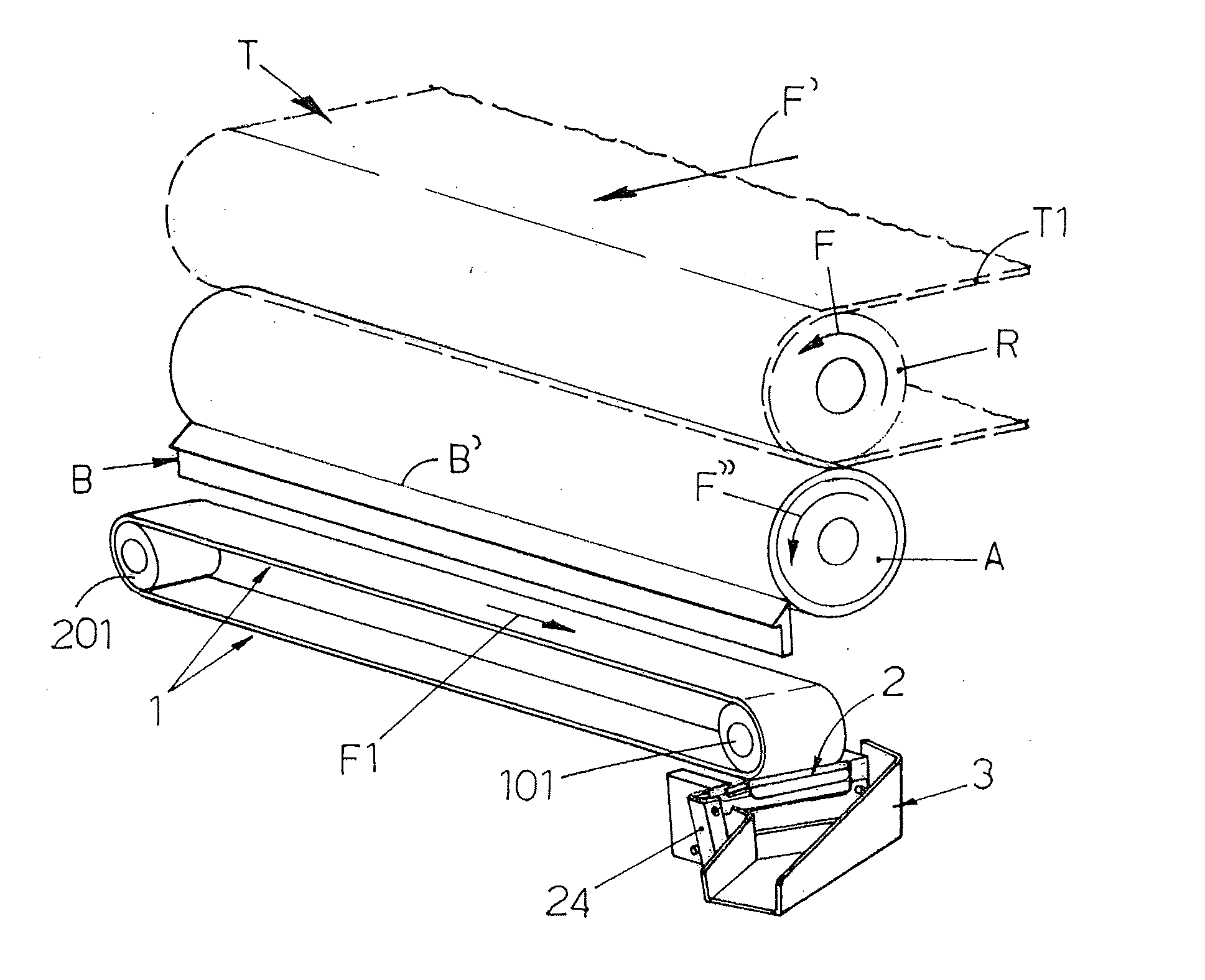
[0007] FIG. 1 shows a perspective and schematic view of the main components of the device;
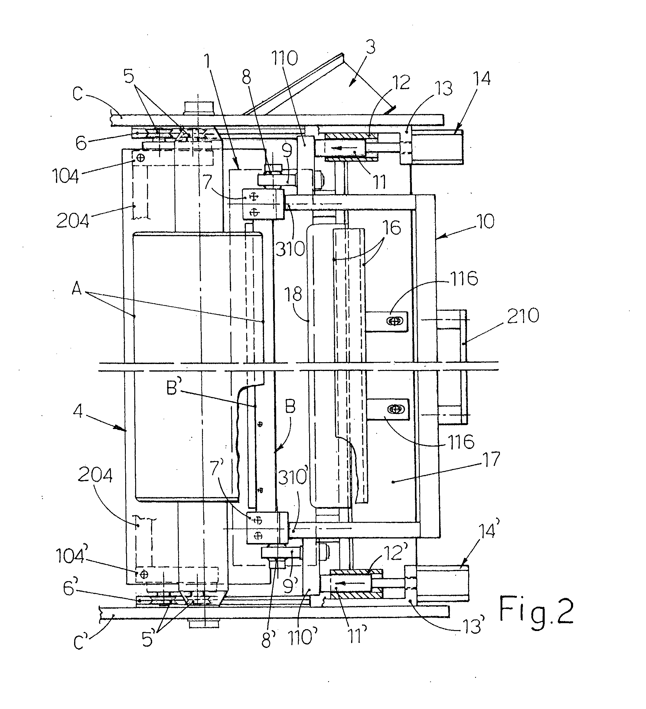
[0008] FIG. 2 shows a top plan view of the device in the working condition;
[0009] FIG. 3 shows a perspective view of one side of the device according to FIG. 2;
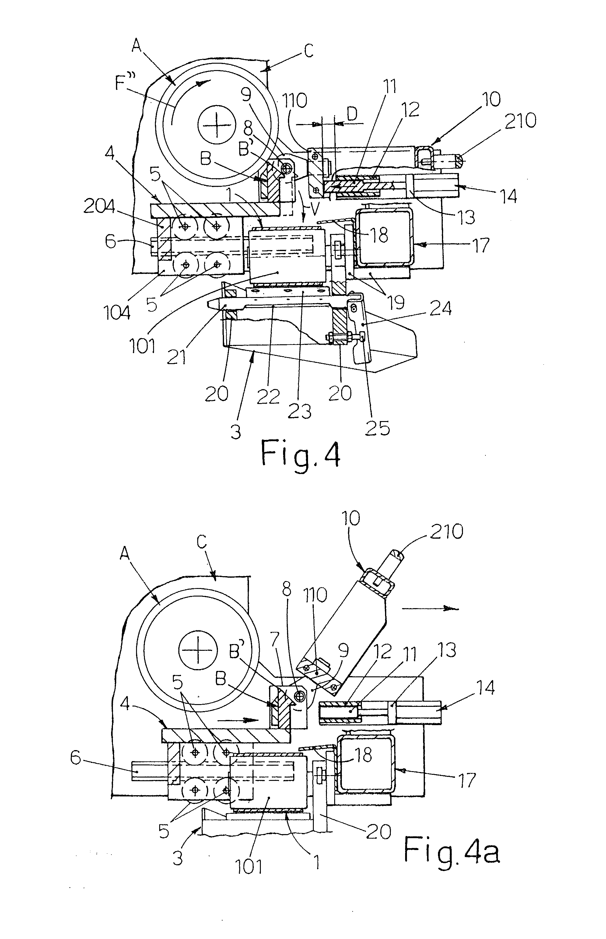
[0010] FIGS. 4, 4a and 4b show the device laterally, with parts cross-sectioned, also in the working condition and in the subsequent rest positions, respectively;
[0011] FIG. 5 shows a top plan view of one side of the device in the condition according to FIG. 4b;
[0012] FIG. 6 shows details of the device shown along the cross-sectional line VI-VI according to FIG. 5;
[0013] FIG. 7 shows, laterally and with parts cross-sectioned, details relating to the doctor blade means for cleaning the secondary conveyor.
DESCRIPTION OF THE PREFERRED EMBODIMENT
[0014] In FIG. 1, T denotes the conveyor of the painting machine, which is driven with one end on the roller R which rotates in the direction of the arrow F and the upper section T1 of which emerges from the painting machine and travels in the same direction indicated by the arrow F'. The letter A denotes the reverse roller which is parallel to the roller R and situated underneath the latter and which operates the lower return section of the conveyor T, rotating in the direction indicated by the arrow F'' and with a speed such as to operate with friction on the conveyor T so as to remove from the latter the paint which has soiled it during transit through the tunnel of the painting machine. B denotes the doctor blade which acts on the reverse roller A so as to remove from it the paint collected and, from the said doctor blade B, the paint falls by means of gravity onto the upper section of a secondary belt conveyor 1 which is operated by suitable means, not shown, in the direction indicated by the arrow F1 so as to convey the paint collected to one end of this secondary conveyor, where cleaning means 2 of any suitable type operate and where a small hopper 3 for collecting and removing the recovered paint is provided. The secondary conveyor 1 may be parallel to the doctor blade B or made be slightly inclined with respect thereto, either along the vertical plane and/or along the horizontal plane. It is evident how the novel solution proposed is highly reliable, how it is able to remove rapidly the paint collected from the reverse roller towards the final removal means 3 and how the paint is not stressed also because it is scraped off in large quantities by the cleaning means 2, since all the paint which falls from the main doctor blade B is conveyed by the conveyor 1 into the small space inside which these cleaning means 2 operate. Compared to the known systems mentioned in the introduction, the novel device also has the advantage that it can be cleaned more easily and rapidly both during operation and at the end of the working shifts or working cycles for which the use of different paints is envisaged, also in the case of the solutions indicated below. From FIGS. 2, 3 and 4 it can be seen that that the doctor blade B with a simple or double sloping profile has a width which is suitably greater than that of the reverse roller A so as to project with sections of sufficient length from the ends of this roller and the said doctor blade is fixed on the side of a main plate 4 situated underneath the said roller A and provided at the ends with sidewalls 104, 104' which are interconnected by at least one cross-piece 204 and on the outer side carry pairs of grooved roller wheels 5, 5' which travel along horizontal, straight and profiled guides 6, 6' perpendicular to the axis of the roller A and fixed onto the said sidewalls C, C' of the structure which rotatably supports the spindle of the reverse roller A. It is understood that, in place of the aforementioned roller wheels, sliding blocks or other suitable means may be envisaged, provided they are such as to ensure that the doctor blade B can be adequately adapted automatically to the reverse roller A as explained later. Still with reference to FIGS. 2 to 4 it can be seen that the plate 4, at the ends of the doctor blade B, has fixed thereon small uprights 7, 7' which have, hinged on their outer side, by means of ball joints 8, 8', short tie-pieces 9, 9' which are fixed perpendicularly with their opposite ends to side lugs 110, 110' of a handle 10 having a U-shaped form in plan view and provided in the middle with a grip 210 and that, when the device is in the active position, it is arranged horizontally, for example with its ends 310, 310' resting against the said small uprights 7, 7'. In this same position, the side lugs 110, 110' of the handle 10 are located in front of thrusters 11, 11' which are slidable inside guides 12, 12' integral with supports 13, 13' which are fixed to the aforementioned sidewalls C, C' and which have, fixed thereon, via their body pneumatic cylinders 14, 14' which with their stem actuate the said thrusters 11, 11' and by means of which the doctor blade B is pushed with its sharp edge B' in close and uniformly distributed contact with the reverse roller A. It is clear how, owing to the means described, the doctor blade may automatically adapt, closely and with precision, to the surface of the reverse roller A, without the need for machining operations or precise assembly of the various parts which form said means. When the doctor blade is in the working position and the cylinders 14, 14' are not activated, it is possible to operate the grip 210 of the handle 10 and retract the entire assembly of the doctor blade B into the position indicated by broken lines in FIG. 4, with a travel movement indicated by D in FIG. 4, until the side lugs 110, 110' shown in FIG. 2 touch the guides 12, 12'. This operation may be performed in a safe manner by the operator and allows the cutting edge. B' of the doctor blade B to be cleaned periodically and rapidly, for example using a scraper mounted on a handle of appropriate length, not shown in the drawings. From FIG. 6 it can be seen that the side lugs 110, 110' of the handle 10 are provided with bottom slots 15 aligned with the stems of the cylinders 14, 14' so as to allow the following operation to be performed. With the cylinders 14, 14' deactivated, it is possible to raise the handle 10 with rotation on the ball joints 8, 8', as shown in FIG. 4a, and it is possible to retract the carriage with the doctor blade B until the latter is positioned underneath a protective cover 16 in the form of an overturned L which with its supports 116 may be fixed adjustably in the correct position on a cross-member 17 in turn fixed with its ends to the sidewalls C, C'. Once the doctor blade has been retracted, the handle 10 can be rotated downwards and the side lugs 110, 110' can be positioned behind the thrusting pins 11, 11', with their slots 15 which are arranged over the stems of the cylinder 14, 14', as shown in FIGS. 4b, 5 and 6. The doctor blade remains securely in the retracted rest position since the lugs 110, 110' are disengaged from the axial action of the stems of the cylinders 14, 14 and are contained between the supports 13, 13' and the guides 12, 12'. In this same rest position, as can be seen from FIG. 4b, the cutting profile B' of the doctor blade B remains positioned underneath the protective cowl 16 so that the said doctor blade B may be cleaned safely by the operator without the latter being able to touch its cutting edge B'. During this cleaning operation and also when the device is in the working position, a special cowl 18 fixed for example to the cross-member 17 ensures correct conveying of the paint on the conveyor 1. The transmission rollers 101, 201 of the secondary conveyor belt 1 and the drive means which operate at least one of these rollers are supported for example by the cross-member 17 by means of an interface structure 19 which also carries supports 20 to which the hopper 3 is removably fixed and on which the cleaning means 2 are mounted, said cleaning means comprising for example a spindle 21 which is mounted rotatably and transversely on the said supports 20 and which has, fixed transversely thereon, a flat spring 22 which supports on the other end a doctor blade 23 which is made of suitable plastic material and which performs scraping and cleaning of the portion of the conveyor belt 1 which passes from the upper section to the lower section, during driving over the roller 101. The spindle 21 of the doctor blade is provided at one end with an adjustable-position handle 24 which may be set so as to cooperate with an adjusting device 25 so as to provide the spring 22 with the necessary flexing movement for ensuring the correct degree of interference between the doctor blade 23 and the conveyor 1. The end of the spring 22 which supports the doctor blade 23 is suitably folded downwards so as to form a drip plate 122 which forces all the paint collected by the doctor blade to fall into the underlying hopper 3. Special microswitches and/or safety sensors, not shown, may be envisaged for detecting the correct working position or rest position of the main components of the device as described
* * * * *
D00000
D00001
D00002
D00003
D00004
D00005
XML
uspto.report is an independent third-party trademark research tool that is not affiliated, endorsed, or sponsored by the United States Patent and Trademark Office (USPTO) or any other governmental organization. The information provided by uspto.report is based on publicly available data at the time of writing and is intended for informational purposes only.
While we strive to provide accurate and up-to-date information, we do not guarantee the accuracy, completeness, reliability, or suitability of the information displayed on this site. The use of this site is at your own risk. Any reliance you place on such information is therefore strictly at your own risk.
All official trademark data, including owner information, should be verified by visiting the official USPTO website at www.uspto.gov. This site is not intended to replace professional legal advice and should not be used as a substitute for consulting with a legal professional who is knowledgeable about trademark law.